

Page 1
Installation Instructions
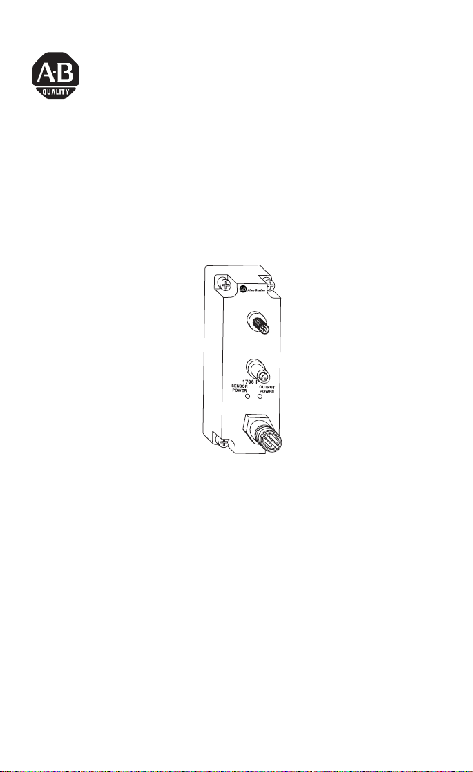
FlexArmor PROFIBUS Field
Termination Plug
Catalog Number 1798-PFTP1
PBUS IN
PUBS OUT
42637
The FlexArmor PROFIBUS Field Termination Plug (Cat. No.
1798-PFTP1) serves as the user connection point for the two field
power busses (sensor power and output power) as well as the
fieldbus network.
The connection point for the field power is capable of conducting a
maximum of 2.5A for the Sensor Power Bus and a maximum of 10A
for the Output Power Bus.
Package Contents
Your package contains:
• 1 FlexArmor PROFIBUS Field Termination Plug (PFTP1)
• installation instructions
(Note: Baseplates and other components are ordered and shipped
separately.)
Publication 1798-IN005B-EN-P - April 2002
Page 2

2 FlexArmor PROFIBUS Field Termination Plug
Important User Information
Because of the variety of uses for the products described in this
publication, those responsible for the application and use of these
products must satisfy themselves that all necessary steps have been
taken to assure that each application and use meets all performance
and safety requirements, including any applicable laws, regulations,
codes and standards. In no event will Allen-Bradley be responsible or
liable for indirect or consequential damage resulting from the use or
application of these products.
Any illustrations, charts, sample programs, and layout examples
shown in this publication are intended solely for purposes of
example. Since there are many variables and requirements associated
with any particular installation, Allen-Bradley does not assume
responsibility or liability (to include intellectual property liability) for
actual use based upon the examples shown in this publication.
Allen-Bradley publication SGI-1.1, Safety Guidelines for the
Application, Installation and Maintenance of Solid-State Control
(available from your local Allen-Bradley office), describes some
important differences between solid-state equipment and
electromechanical devices that should be taken into consideration
when applying products such as those described in this publication.
Reproduction of the contents of this copyrighted publication, in
whole or part, without written permission of Rockwell Automation, is
prohibited.
Throughout this publication, notes may be used to make you aware
of safety considerations. The following annotations and their
accompanying statements help you to identify a potential hazard,
avoid a potential hazard, and recognize the consequences of a
potential hazard:
ATTENTION
Identifies information about practices or
circumstances that can lead to personal injury or
death, property damage, or economic loss.
!
Publication 1798-IN005B-EN-P - April 2002
Page 3

FlexArmor PROFIBUS Field Termination Plug 3
IMPORTANT
ATTENTION
!
Identifies information that is critical for
successful application and understanding of the
product.
Environment and Enclosure
This equipment is intended for use in a
Pollution Degree 2 industrial environment, in
overvoltage Category II applications (as defined
in IEC publication 60664-1), at altitudes up to
2000 meters without derating.
This equipment is considered Group 1, Class A
industrial equipment according to IEC/CISPR
Publication 11. Without appropriate precautions,
there may be potential difficulties ensuring
electromagnetic compatibility in other
environments due to conducted as well as
radiated disturbance.
This equipment is supplied as "enclosed"
equipment. It should not require additional
system enclosure when used in locations
consistent with the enclosure type ratings stated
in the Specifications section of this publication.
Subsequent sections of this publication may
contain additional information regarding specific
enclosure type ratings, beyond what this
product provides, that are required to comply
with certain product safety certifications.
See NEMA Standards publication 250 and IEC
publication 60529, as applicable, for
explanations of the degrees of protection
provided by different types of enclosure. Also,
see the appropriate sections in this publication,
as well as the Allen-Bradley publication 1770-4.1
("Industrial Automation Wiring and Grounding
Guidelines"), for additional installation
requirements pertaining to this equipment.
Publication 1798-IN005B-EN-P - April 2002
Page 4

4 FlexArmor PROFIBUS Field Termination Plug
Related Publications
• For software configuration information, refer to the 1798-APB
User Manual, publication no. 1798-UM002.
• For installation instructions for the 1798-APB, see publication
no. 1798-IN011.
Install Your FlexArmor Field Termination Plug
To install the module:
• Mount the PFTP1
• Connect external wiring
These steps are explained in more detail in the following
procedures.
For instructions on how to mount the FlexArmor Baseplate,
refer to publication no. 1798-IN003.
Preventing Electrostatic Discharge
This equipment is sensitive to electrostatic
discharge, which can cause internal damage and
affect normal operation. Follow these guidelines
ATTENTION
!
when you handle this equipment:
• Touch a grounded object to discharge
potential static.
• Wear an approved grounding wriststrap.
• Do not touch connectors or pins on
component boards.
• Do not touch circuit components inside the
equipment.
• If available, use a static-safe workstation.
• When not in use, store the equipment in
appropriate static-safe packaging.
Mount the Field Termination Plug
To mount the Field Termination Plug:
1. Place the PFTP1 on the left-most slot of the Baseplate.
Publication 1798-IN005B-EN-P - April 2002
Page 5

FlexArmor PROFIBUS Field Termination Plug 5
2. Screw down the module retaining screws to ensure IP67
compliance.
IMPORTANT
Torque the screws to 0.5-0.7 Nm. (4.43 - 6.2 inch
pounds).
Connect External Wiring
Connect external wiring to the PROFIBUS adapter as shown below.
1. Connect the PROFIBUS in-going cable to the 12 mm male
connector labeled PBUS IN.
Name Pin
Number
+5VBUS 1 Supply voltage of the
A-Line 2 Negative RxD/TxD according
GNDBUS 3 Supply voltage of the
B-Line 4 Positive RxD/TxD according
Shield 5 Connected to Protective
2. Connect the PROFIBUS out-going cable to the 12 mm female
connector labeled PUBS OUT.
Description
terminating resistance
to PROFIBUS specification
terminating resistance
(GND)
to PROFIBUS specification
Ground
43267
3
2
5
4
1
1
4
5
3
Male
connector
(PBUS IN)
2
Female
connector
(PBUS OUT)
3. Connect 24V dc power to sensor voltage for adapter and input
module power.
4. Connect 24V dc power to output voltage for output module
power.
Publication 1798-IN005B-EN-P - April 2002
Page 6

6 FlexArmor PROFIBUS Field Termination Plug
Pin Function
1 Output Power -
2 Sensor Power -
3 Protective Gnd
4 Sensor Power +
5 Output Power +
1
2
3
Male Connector
4
Troubleshooting with the Indicators
The following table describes status indicators on the Field
Termination Plug.
Indicator Status
Green
Off
Power ON
Power OFF or reverse polarity
PROFIBUS Field Termination Plug Specifications
Following are specifications for the PROFIBUS Field Termination
Plug.
5
43268
1798-PFTP1 Specifications
Voltage Rating 28.8V dc maximum
Sensor and Adapter Power Current 2.5A
Output Power Current 10A
Sensor/Output Voltage 10-28.8V dc
Sensor/Output Power Connector 0.875 in male
PROFIBUS Connector M12 male and female
PROFIBUS Cable Use appropriate cable
Dimensions (H x W x D) 1.5in x 4.5in x 1.0in
Publication 1798-IN005B-EN-P - April 2002
Page 7

FlexArmor PROFIBUS Field Termination Plug 7
1798-PFTP1 Specifications (continued)
Operational Temperature IEC 60068-2-1 (Test Ad, Operating Cold),
Storage Temperature IEC 60068-2-1 (Test Ab, Un-packaged Non-operating
Shock IEC60068-2-27 (Test Ea, Unpackaged shock):
Emissions CISPR 11:
ESD Immunity IEC 61000-4-2:
Radiated RF Immunity IEC 61000-4-3:
EFT/B Immunity IEC 61000-4-4:
Surge Transient Immunity IEC 61000-4-5:
Conducted RF Immunity IEC 61000-4-6:
Vibration IEC60068-2-6 (Test Fc, Operating):
IEC 60068-2-2 (Test Bd, Operating Dry Heat),
IEC 60068-2-14 (Test Nb, Operating Thermal Shock):
–20 to 60°C (–4 to 140°F)
Cold),
IEC 60068-2-2 (Test Bb, Un-packaged Non-operating
Dry Heat),
IEC 60068-2-14 (Test Na, Un-packaged Non-operating
Thermal Shock):
–40 to 85°C (–40 to 185°F)
Operating 30g
Non-operating 50g
Group 1, Class A
4kV contact discharges
10V/m with 1kHz sine-wave 80%AM from 80MHz to
1000MHz
±2kV at 5kHz on power ports
±1kV at 5kHz on signal ports
±1kV line-line(DM) and ±2kV line-earth(CM) on power
ports
+
1kV line-earth (CM) on shielded ports
10Vrms with 1kHz sine-wave 80%AM from 150kHz to
80MHz
5g @ 10-500Hz
Publication 1798-IN005B-EN-P - April 2002
Page 8

1798-PFTP1 Specifications (continued)
ConductorsWire Size
Category
16 AWG stranded wire
1, 2
2
Enclosure Type Rating Meets IP67
Agency Certification
(When product is marked)
c-UL-us UL Listed Industrial Control Equipment,
certified for US and Canada
UL UL Listed Industrial Control Equipment
3
CE
European Union 89/336/EEC EMC
Directive, compliant with:
EN 50081-2; Industrial Emissions
EN 50082-2; Industrial Immunity
EN 61326; Meas./Control/Lab., Industrial
Requirements
EN 61000-6-2; Industrial Immunity
3
C-Tick
Australian Radiocommunications Act,
compliant with:
AS/NZS 2064; Industrial Emissions
1. You use this conductor category information for planning conductor routing as
described in the system level installation manual.
2. See pub. 1770-4.1, Programmable Controller Wiring and Grounding Guidelines.
3. See the Product Certification link at www.ab.com for Declarations of Conformity,
Certificates, and other certification details.
Allen-Bradley is a registered trademark of Rockwell Automation.
DeviceNet is a trademark of Open DeviceNet Vendor Association (ODVA).
RSNetWorx for DeviceNet is a trademark of Rockwell Software, Inc.
Publication 1798-IN005B-EN-P - April 2002 PN 957689-19
Supersedes Publ ication 1798-IN005A-EN- P - March 2002 Copyright © 2002 Rockwell Automatio n. All rights reserved. Printed in the U.S.A.
 Loading...