

Page 1
Installation Instructions
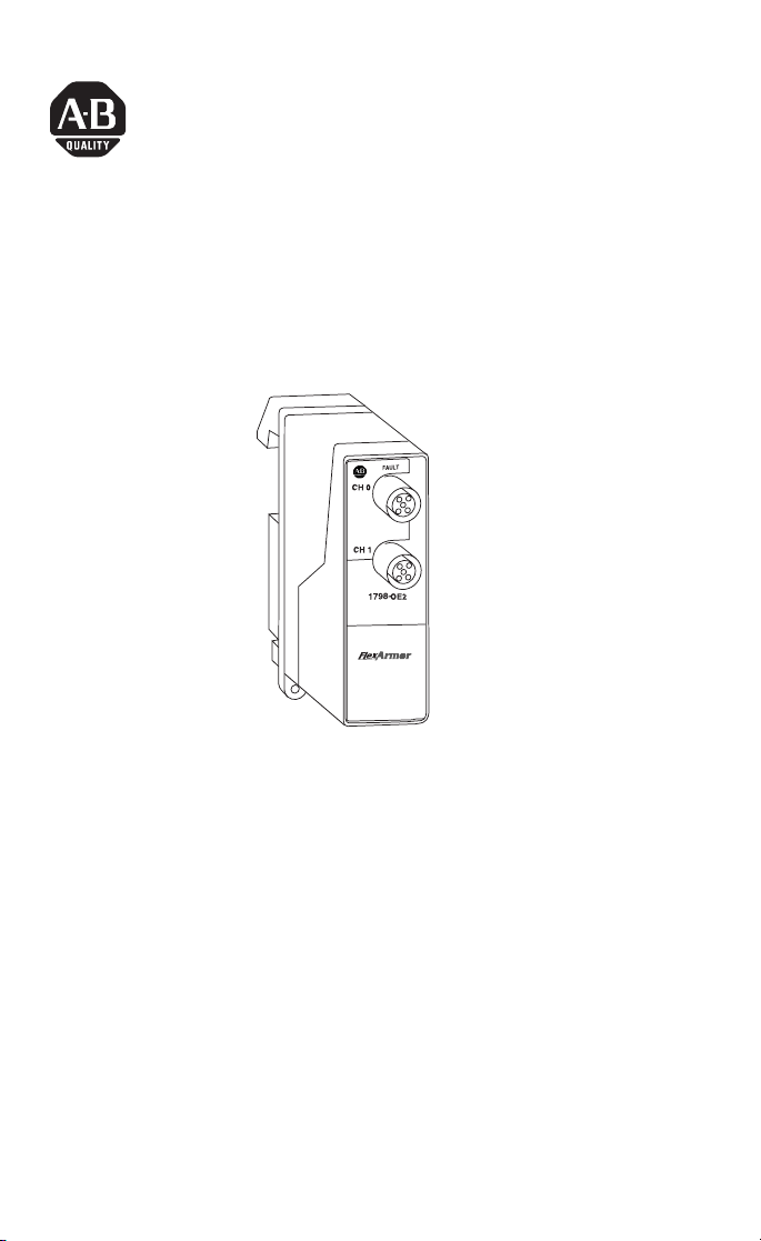
FlexArmor Analog Output Module
Catalog Number 1798-OE2
43000
The FlexArmor I/O module (Cat. No. 1798-OE2) mounts in a
FlexArmor Baseplate. Use compatible sealed cordsets to connect all
field side wiring. All cordsets must be shielded to achieve proper
noise immunity.
The 1798-OE2 module provides connections for up to 2 single ended
non-isolated outputs. This module has two 12 mm connectors
configured for analog output. A diagnostic feature for this module
includes sensor power short-circuit detection. The outputs can be
either voltage or current.
Package Contents
Your package contains one FlexArmor 1798-OE2 module and these
installation instructions. (Note: Baseplates and other components are
ordered and shipped separately.)
Publication 1798-IN009A-EN-P - April 2002
Page 2

2 FlexArmor Analog Output Module
ATTENTION
!
Important User Information
Because of the variety of uses for the products described in this
publication, those responsible for the application and use of these
products must satisfy themselves that all necessary steps have been
taken to assure that each application and use meets all performance
and safety requirements, including any applicable laws, regulations,
codes and standards. In no event will Allen-Bradley be responsible or
liable for indirect or consequential damage resulting from the use or
application of these products.
Any illustrations, charts, sample programs, and layout examples
shown in this publication are intended solely for purposes of
example. Since there are many variables and requirements associated
with any particular installation, Allen-Bradley does not assume
responsibility or liability (to include intellectual property liability) for
actual use based upon the examples shown in this publication.
Allen-Bradley publication SGI-1.1, Safety Guidelines for the
Application, Installation and Maintenance of Solid-State Control
(available from your local Allen-Bradley office), describes some
important differences between solid-state equipment and
electromechanical devices that should be taken into consideration
when applying products such as those described in this publication.
Reproduction of the contents of this copyrighted publication, in
whole or part, without written permission of Rockwell Automation, is
prohibited.
Throughout this publication, notes may be used to make you aware
of safety considerations. The following annotations and their
accompanying statements help you to identify a potential hazard,
avoid a potential hazard, and recognize the consequences of a
potential hazard:
Publication 1798-IN009A-EN-P - April 2002
Identifies information about practices or
circumstances that can lead to personal injury or
death, property damage, or economic loss.
Page 3

FlexArmor Analog Output Module 3
IMPORTANT
ATTENTION
!
Identifies information that is critical for
successful application and understanding of the
product.
Environment and Enclosure
This equipment is intended for use in a Pollution
Degree 2 industrial environment, in overvoltage
Category II applications (as defined in IEC
publication 60664-1), at altitudes up to 2000
meters without derating.
This equipment is considered Group 1, Class A
industrial equipment according to IEC/CISPR
Publication 11. Without appropriate precautions,
there may be potential difficulties ensuring
electromagnetic compatibility in other
environments due to conducted as well as
radiated disturbance.
This equipment is supplied as "enclosed"
equipment. It should not require additional
system enclosure when used in locations
consistent with the enclosure type ratings stated
in the Specifications section of this publication.
Subsequent sections of this publication may
contain additional information regarding specific
enclosure type ratings, beyond what this product
provides, that are required to comply with
certain product safety certifications.
See NEMA Standards publication 250 and IEC
publication 60529, as applicable, for
explanations of the degrees of protection
provided by different types of enclosure. Also,
see the appropriate sections in this publication,
as well as the Allen-Bradley publication 1770-4.1
("Industrial Automation Wiring and Grounding
Guidelines"), for additional installation
requirements pertaining to this equipment.
Publication 1798-IN009A-EN-P - April 2002
Page 4

4 FlexArmor Analog Output Module
ATTENTION
!
IMPORTANT
Related Publications
• For DeviceNet software configuration information, refer to the
1798-ADN User Manual, publication 1798-UM001.
• For PROFIBUS configuration information, refer to the
1798-APB User Manual, publication 1798-UM002.
Install the Module into the Baseplate
For instructions on how to mount the FlexArmor Baseplate, refer to
publication no. 1798-IN003.
Preventing Electrostatic Discharge
This equipment is sensitive to electrostatic
discharge, which can cause internal damage and
affect normal operation. Follow these guidelines
when you handle this equipment:
• Touch a grounded object to discharge
potential static.
• Wear an approved grounding wriststrap.
• Do not touch connectors or pins on
component boards.
• Do not touch circuit components inside the
equipment.
• If available, use a static-safe workstation.
• When not in use, store the equipment in
appropriate static-safe packaging.
To install the module into the Baseplate:
Publication 1798-IN009A-EN-P - April 2002
1. Hold the module at an angle and engage the top of the
module in the indention on the rear of the Baseplate.
2. Press the module down flush with the panel until the locking
lever locks.
3. Repeat these steps for each I/O module and each remaining
Baseplate I/O slot.
I/O modules can be installed in any slot location
to the right of the adapter module. The adapter is
capable of addressing up to eight I/O modules.
Page 5

FlexArmor Analog Output Module 5
4. Screw down the module retaining screws to ensure IP67
compliance.
IMPORTANT
• Torque the screws to 0.5-0.7 Nm. (4.43 - 6.2
inch pounds).
• Dust caps must have 4 inch pounds of torque
to maintain IP67 compliance.
Connect the Cordset to the FlexArmor Module
The module uses 5 pin micro (12mm) style PCB mounted connectors.
Two micro caps cover the I/O connectors on the module. Remove
the caps and connect your cables to the appropriate ports. Keep the
caps in place on any unused connector to maintain the IP67 rating.
A pinout diagram for the connectors is shown below.
Female Input Micro-Connector
(View into Socket)
Pin 1 Sensor Power
Pin 2 Current Output
Pin 3 Sensor Common
Pin 4 Voltage Output
Pin 5 Not Used
42652
ATTENTION
!
• Make sure all connectors and caps are
securely tightened to properly seal the
connections against leaks and maintain IP67
requirements.
• For maximum noise immunity, input and
output cable return wires must be properly
terminated. When inputs and outputs are
connected in loopback, return wires should
be connected together.
• I/O cable length should be less than 30
meters.
Publication 1798-IN009A-EN-P - April 2002
Page 6

6 FlexArmor Analog Output Module
Troubleshooting with the Indicators
The following table describes the status indicator on the analog
output modules.
I/O Status Indicators
Function Indicator Status
Fault
LED
Red
Off
Sensor Power Short
Normal
Specifications
Specifications - 1798-OE2 Analog Output Module
Module Type Analog Output
Number of Channels 2 single-ended, non-isolated
Resolution Bits
Data Format 16 bit; 2’s complement; left-justified
Conversion Type Pulse width modulation
Conversion Rate 1.024 ms - All channels
Current Terminal 4-20 mA; 0-20 mA (0 mA output until the module is
Voltage Terminal ±10V; 0-10V - 3 mA maximum (0V output until the
Step Response to 63% of FS 24 mS
Output Load on Voltage 3 mA maximum
Resistive Load on mA
Output
Absolute Accuracy
Accuracy Drift
Calibration None Required
FlexBus Current 10 mA maximum
Power dissipation 2.5W @ 28.8V dc
Sensor Source Current
(per connector)
Thermal Dissipation 8.5 BTU/hr @ 28.8V dc
Indicator 1 fault LED Indicator - red
External DC Power
Voltage (24V dc nom.)
Current
Voltage/Cnt
Current/Cnt
Voltage Terminal
Current Terminal
Voltage Terminal
Current Terminal
12 + sign
2.56 mV
5.13 uA
configured)
module is configured)
15-750 ohms
0.133% FS @ 25°C
0.425% FS @ 25°C
0.0045% FS per°C
0.0069% FS per°C
50 mA
10-28.8V dc; 5% AC ripple
85 mA @ 24V dc
Publication 1798-IN009A-EN-P - April 2002
Page 7

FlexArmor Analog Output Module 7
Specifications - 1798-OE2 Analog Output Module (continued)
Dimensions
(H x D x W)
Operational Temperature IEC 60068-2-1 (Test Ad, Operating Cold),
Storage Temperature IEC 60068-2-1 (Test Ab, Un-packaged Non-operating
Shock IEC60068-2-27 (Test Ea, Unpackaged shock):
Emissions CISPR 11:
ESD Immunity IEC 61000-4-2:
Radiated RF Immunity IEC 61000-4-3:
EFT/B Immunity IEC 61000-4-4:
Surge Transient Immunity IEC 61000-4-5:
Conducted RF Immunity IEC 61000-4-6:
Conductors See publication DN-6.7.2
Vibration IEC60068-2-6 (Test Fc, Operating):
Enclosure Meets IP67
Agency Certification
(When product is marked)
1. See the Product Certification link at www.ab.com for Declarations of Conformity,
Certificates, and other certification details.
118 mm x 57 mm x 40 mm
4.63 in. x 2.25 in. x 1.58 in.
IEC 60068-2-2 (Test Bd, Operating Dry Heat),
IEC 60068-2-14 (Test Nb, Operating Thermal Shock):
-20 to 60°C (-4 to 140°F)
Cold),
IEC 60068-2-2 (Test Bb, Un-packaged Non-operating Dry
Heat),
IEC 60068-2-14 (Test Na, Un-packaged Non-operating
Thermal Shock):
–40 to 85°C (–40 to 185°F)
Operating 30g
Non-operating 50g
Group 1, Class A
6kV contact discharges
8kV air discharges
10V/m with 1kHz sine-wave 80%AM from 30MHz to
2000MHz
10V/m with 200Hz 50% Pulse 100%AM at 900MHz
±2kV at 5kHz on power ports
±2kV at 5kHz on signal ports
±1kV line-line(DM) and ±2kV line-earth(CM) on power
ports
±1kV line-line(DM) and ±2kV line-earth(CM) on signal
ports
10Vrms with 1kHz sine-wave 80%AM from 150kHz to
80MHz
5g @ 10-500Hz
c-UL-us UL Listed Industrial Control Equipment, certified
for US and Canada
UL UL Listed Industrial Control Equipment
1
European Union 89/336/EEC EMC Directive,
CE
compliant with:
EN 50081-2; Industrial Emissions
EN 50082-2; Industrial Immunity
EN 61326; Meas./Control/Lab., Industrial
Requirements
EN 61000-6-2; Industrial Immunity
1
Australian Radiocommunications Act, compliant
C-Tick
with: AS/NZS 2064; Industrial Emissions
Publication 1798-IN009A-EN-P - April 2002
Page 8

Allen-Bradley is a registered trademark of Rockwell Automation.
DeviceNet is a trademark of Open DeviceNet Vendor Association (ODVA).
RSNetWorx for DeviceNet is a trademark of Rockwell Software, Inc.
Publication 1798-IN009A-EN-P - April 2002 PN 957564-46
Copyright © 2002 Rockwell Automation. All rights reserv ed. Printed in the U.S.A.
 Loading...