

Page 1
Installation Instructions
FlexArmor 24V dc Sourcing
Output Modules
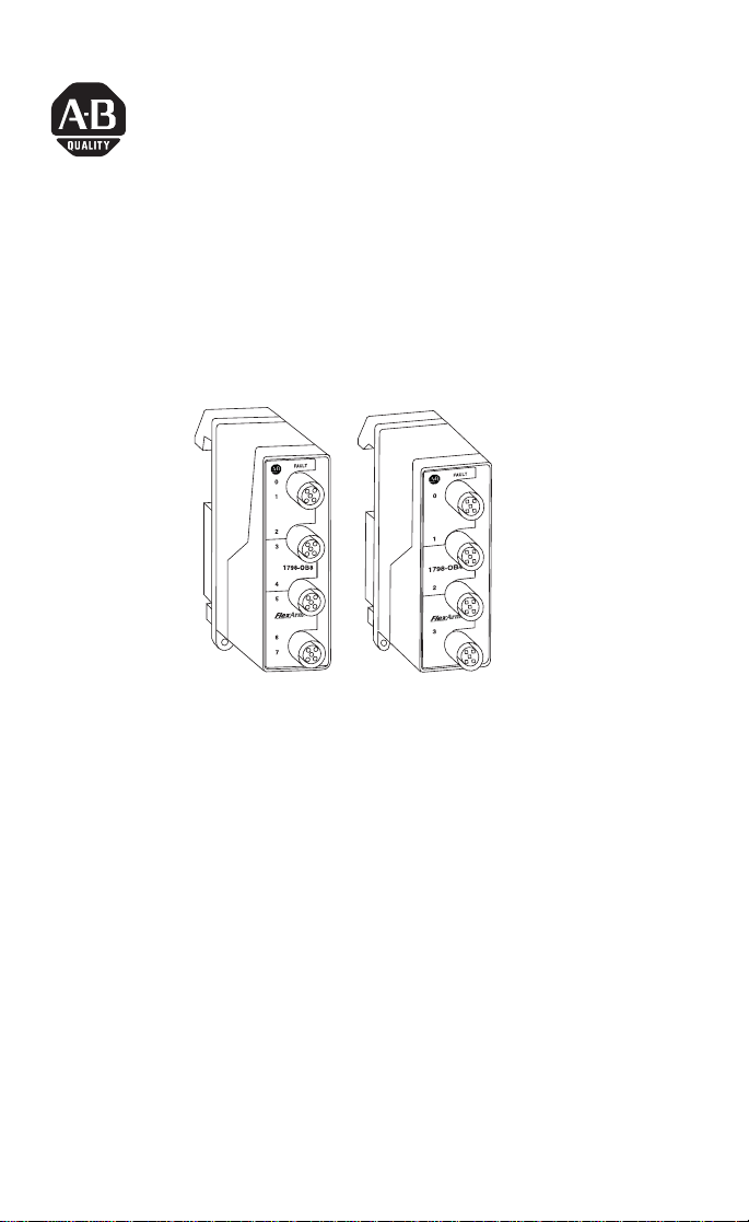
Catalog Number 1798-OB4E & 1798-OB8E
42639
The FlexArmor I/O modules (Cat. No. 1798-OB4E & 1798-OB8E)
mount in a FlexArmor Baseplate. Use compatible sealed cordsets to
connect all field side wiring.
The 1798-OB4E module provides connections for up to 4 outputs.
The 1798-OB8E module provides connections for up to 8 outputs.
Both of these modules have four 12 mm connectors. Outputs are 24V
dc configured for sinking devices. A diagnostic feature for both
modules includes output short-circuit detection.
Package Contents
Your package contains:
• 1 FlexArmor -OB4E or -OB8E module
• installation instructions
(Note: Baseplates and other components are ordered and shipped
separately.)
Publication 1798-IN002A-EN-P - January 2001
Page 2

2 FlexArmor 24V dc Sourcing Output Modules
European Union Directive Compliance
If this product has the CE mark it is approved for installation within
the European Union and EEA regions. It has been designed and
tested to meet the following directives.
EMC Directive
This product is tested to meet Council Directive 89/336/EEC
Electromagnetic Compatibility (EMC) and the following standards, in
whole or in part, documented in a technical construction file:
• EN 50081-2 EMC - Generic Emission Standard, Part 2 -
Industrial Environment
• EN 50082-2 EMC - Generic Immunity Standard, Part 2 -
Industrial Environment
This product is intended for use in an industrial environment.
Low Voltage Directive
This product is tested to meet Council Directive 73/23/EEC Low
Voltage, by applying the safety requirements of EN 61131-2
Programmable Controllers, Part 2 - Equipment Requirements and
Tests.
For specific information required by EN 61131-2, see the appropriate
sections in this publication, as well as the following Allen-Bradley
publications:
• Industrial Automation Wiring and Grounding Guidelines For
Noise Immunity, publication 1770-4.1
• Automation Systems Catalog, publication B113
Related Publications
For software configuration information, refer to the 1798-ADN User
Manual, publication 1798-UM001A-US-P and the 1798-APB User
Manual, publication 1798-UM002A-EN-P.
Publication 1798-IN002A-EN-P - January 2001
Page 3

FlexArmor 24V dc Sourcing Output Modules 3
Install Your FlexArmor I/O Module
To install the module:
• Install the modules into the Baseplate
• Connect the cordsets
• Communicate with the module
These steps are explained in more detail in the following
procedures.
For instructions on how to mount the FlexArmor Baseplate,
refer to publication no. 1798-IN003A-EN-P.
Install the Modules into the Baseplate
To install the modules into the Baseplate:
1. Hold the module at an angle and engage the top of the
module in the indention on the rear of the Baseplate.
2. Press the module down flush with the panel until the locking
lever locks.
3. Repeat these steps for each I/O module and each remaining
Baseplate I/O slot.
IMPORTANT
Screw down the module retaining screws to ensure IP67 compliance.
IMPORTANT
I/O modules can be installed in any slot location
to the right of the adapter module. The adapter is
capable of addressing up to eight I/O modules.
• Torque the screws to 0.5-0.7 Nm. (4.43 - 6.2
inch pounds).
• Dust caps must have 4 inch pounds of torque
to maintain IP67 compliance.
Publication 1798-IN002A-EN-P - January 2001
Page 4
4 FlexArmor 24V dc Sourcing Output Modules
Connect the Cordset to the FlexArmor Module
These modules use 5 pin micro (12mm) style PCB mounted
connectors.
Four micro caps cover the I/O connectors on both your modules.
Remove the caps and connect your cables to the appropriate ports.
Keep the caps in place on any unused connector to maintain the IP67
rating.
Refer to publication no. 889-CP0021A-EN-P for compatible Rockwell
Automation cables and cordsets.
A pinout diagram for the connectors is shown below.
Output Micro-Connector
(View into Socket)
Pin 1 Not Used
Pin 2 Output B (OB8E modules only)
Pin 3 Output Common
Pin 4 Output A
Pin 5 Not Used
42652
ATTENTION
!
Publication 1798-IN002A-EN-P - January 2001
• Make sure all connectors and caps are
securely tightened to properly seal the
connections against leaks and maintain IP67
requirements.
• For maximum noise immunity, input and
output cable return wires must be properly
terminated. When inputs and outputs are
connected in loopback, return wires should
be connected together.
• I/O cable length should be less than 30
meters.
Page 5

FlexArmor 24V dc Sourcing Output Modules 5
Communicate with Your FlexArmor System
The FlexArmor DeviceNet adapter module supports multiple
communication choices. The network master makes the actual
communication choice. The choices are:
Polled - data is sent by the adapter in response to received data.
Strobe - data is sent by the adapter in response to the strobe
command. The single bit allocated to the adapter in the strobe
message is not used. If the configured size of the input data (sent
from the adapter) is greater than 8 bytes, the strobe connection
establishment will fail. In this case, the input size must be
re-configured to 8 bytes or less.
Change of State - data is sent by the adapter based on detection of
any changed value within the input data. Data is independently
received based on change of state from the sender. Data in both
directions can be acknowledged or unacknowledged depending on
the run time configuration of the system.
Cyclic - data is sent cyclically by the adapter based on a configured
time value. Data is independently received cyclically from the sender.
Data in both directions can be acknowledged or unacknowledged
depending on the run time configuration of the system.
Troubleshooting with the Indicators
The following table describes status indicators on digital output
modules.
I/O Status Indicators
Function Indicator Status
Outputs
Outputs
Fault LED
Yellow
Off
Red
Off
Output ON
Output OFF
One or more outputs shorted
Normal
Publication 1798-IN002A-EN-P - January 2001
Page 6

6 FlexArmor 24V dc Sourcing Output Modules
Specifications
Output Module Specifications
Specifications 1798-0B4E 1798-0B8E
Module Type Digital Output, Sourcing Digital Output, Sourcing
Number of Channels 1 group of 4 1 group of 8
On-state Voltage 10-28.8V dc; 24V dc nominal 10-28.8V dc; 24V dc nominal
On-state Current
(per channel)
On-state Current (per module) 4.0A per module 5.0A per module
Off-state Voltage 28.8V dc maximum 28.8V dc maximum
Off-State Current 0.5 mA maximum leakage 0.5 mA maximum leakage
On-State Voltage Drop 0.5V dc maximum drop 0.5V dc maximum drop
Surge Current 2.0A for 50 ms
Isolation Voltage 850V dc for 1 second 850V dc for 1 second
Delay Times: Off to On
FlexBus Current 60 mA maximum 60 mA maximum
Power Dissipation 2.4 W @ 28.8 V dc 2.9 W @ 28.8 V dc
Thermal Dissipation 8.2 BTU/hr. @ 28.8V dc 9.9 BTU/hr. @ 28.8V dc
Indicators 4 channel status - yellow
External DC Power
Dimensions
(H x D x W)
Environmental Conditions:
Operating Temperature
Storage Temperature
Shock: Operating
Non-Operating
Vibration
Conductors See publication DN-6.7.2
Cordsets 5 pin micro (12mm) style connectors
Enclosure Meets IP67
Agency Certification
(When product is marked)
On to Off
Voltage (24V dc nom.)
Current
1.0A per channel 1.0A per channel
(Repeatable every 2 seconds)
0.5 ms maximum
1.0 ms maximum
4 fault LED indicators- red
10-28.8V dc; 5% AC ripple
4.0A maximum
118 mm X 57 mm X 40 mm
4.63 in. X 2.25 in. X 1.58 in.
-20 to 60°C (-4 to 140°F)
-40 to 85°C (-40 to 185°F)
30G peak, 11±1ms pulse width
50G peak, 11±1ms pulse width
5G @ 10-500Hz per IEC 68-2-6
(see graph on next page)
CUL listed
UL Hazardous Class 1, Division 2, Groups A, B, C, D certified
CE marked for all applicable directives
2.0A for 50 ms
(Repeatable every 2 seconds)
0.5 ms maximum
1.0 ms maximum
8 channel status - yellow
8 fault LED indicators - red
10-28.8V dc; 5% AC ripple
5.0A maximum
118 mm X 57 mm X 40 mm
4.63 in. X 2.25 in. X 1.58 in.
-20 to 60°C (-4 to 140°F)
-40 to 85°C (-40 to 185°F)
30G peak, 11±1ms pulse width
50G peak, 11±1ms pulse width
5G @ 10-500Hz per IEC 68-2-6
(see graph on next page)
marked for all applicable acts
N223
Publication 1798-IN002A-EN-P - January 2001
Page 7

FlexArmor 24V dc Sourcing Output Modules 7
Derating Curve
1A
0.5A
Output Current (per channel)
42700
-20° 40° 60°
Ambient Temperature (Celsius)
Hazardous Location Approval
The following information applies only to products marked
with Hazardous Location Approval, when operating in
hazardous locations:
Products marked “CL I, DIV 2, GP A, B, C, D” are suitable for use in
Class I Division 2 Groups A, B, C, D, Hazardous Locations and
nonhazardous locations only. Each product is supplied with markings
on the rating nameplate indicating the hazardous location
temperature code. When combining products within a system, the
most adverse temperature code (lowest “T” number) may be used to
help determine the overall temperature code of the system.
Combinations of equipment in your system are subject to
investigation by the local Authority Having Jurisdiction at the time of
installation.
Publication 1798-IN002A-EN-P - January 2001
Page 8

8 FlexArmor 24V dc Sourcing Output Modules
WARNING
!
WARNING
!
WARNING
!
EXPLOSION HAZARD -
• Do not disconnect equipment unless power
has been removed or the area is known to be
nonhazardous.
• Do not disconnect connections to this
equipment unless power has been removed
or the area is known to be nonhazardous.
Secure any external connections that mate to
this equipment by using screws, sliding
latches, threaded connectors, or other means
provided with this product.
• Substitution of components may impair
suitability for Class I, Division 2.
• If this product contains batteries, they must
only be changed in an area known to be
nonhazardous.
Use supply wires suitable for 30°C above
surrounding ambient.
When used in a Class I, Division 2, hazardous
location, this equipment must be mounted in a
suitable enclosure with proper wiring method that
complies with the governing electrical codes.
Publication 1798-IN002A-EN-P - January 2001
Page 9

FlexArmor 24V dc Sourcing Output Modules 9
Les informations suivantes ne concernent que les produits
marqués pour une utilisation en environnements dangereux :
Les produits marqués « CL I, DIV 2, GP A, B, C, D » ne conviennent
qu’à une utilisation en environnements de Classe I Division 2
Groupes A, B, C, D dangereux et non dangereux. Chaque produit est
livré avec des marquages sur sa plaque d’identification qui indiquent
le code de température pour les environnements dangereux. Lorsque
plusieurs produits sont combinés dans un système, le code de
température le plus défavorable (code de température le plus faible)
peut être utilisé pour déterminer le code de température global du
système. Les combinaisons d’équipements dans le système sont
sujettes à inspection par les autorités locales qualifiées au moment de
l’installation.
AVERTISSEMENT
!
AVERTISSEMENT
!
RISQUE D’EXPLOSION -
• Couper le courant ou s’assurer que
l’environnement est classé non dangereux
avant de débrancher l’équipement.
• Couper le courant ou s’assurer que
l’environnement est classé non dangereux
avant de débrancher les connecteurs. Fixer
tous les connecteurs externes reliés à cet
équipement à l’aide de vis, loquets
coulissants, connecteurs filetés ou autres
moyens fournis avec ce produit.
• La substitution de composants peut rendre cet
équipement inadapté à une utilisation en
environnement de Classe I, Division 2.
• S’assurer que l’environnement est classé non
dangereux avant de changer les piles.
Utiliser des fils d’alimentation qui conviennent à
une température de 30°C au-dessus de la
température ambiante.
Publication 1798-IN002A-EN-P - January 2001
Page 10

10 FlexArmor 24V dc Sourcing Output Modules
AVERTISSEMENT
!
Pour une utilisation en environnement de classe i,
division 2 dangereux, cet equipement doit etre
monte dans un boitier avec un cablage approprie
conforme aux normes electriques en vigueur.
Publication 1798-IN002A-EN-P - January 2001
Page 11

Notes:
FlexArmor 24V dc Sourcing Output Modules 11
Publication 1798-IN002A-EN-P - January 2001
Page 12

Allen-Bradley is a registered trademark of Rockwell Automation.
DeviceNet is a trademark of Open DeviceNet Vendor Association (ODVA).
RSNetWorx for DeviceNet is a trademark of Rockwell Software, Inc.
Publication 1798-IN002A-EN-P - January 2001 PN 957259-72
© 2001 Rockwell Internati onal Corporation. Printed in USA
 Loading...