

Page 1
Installation Instructions
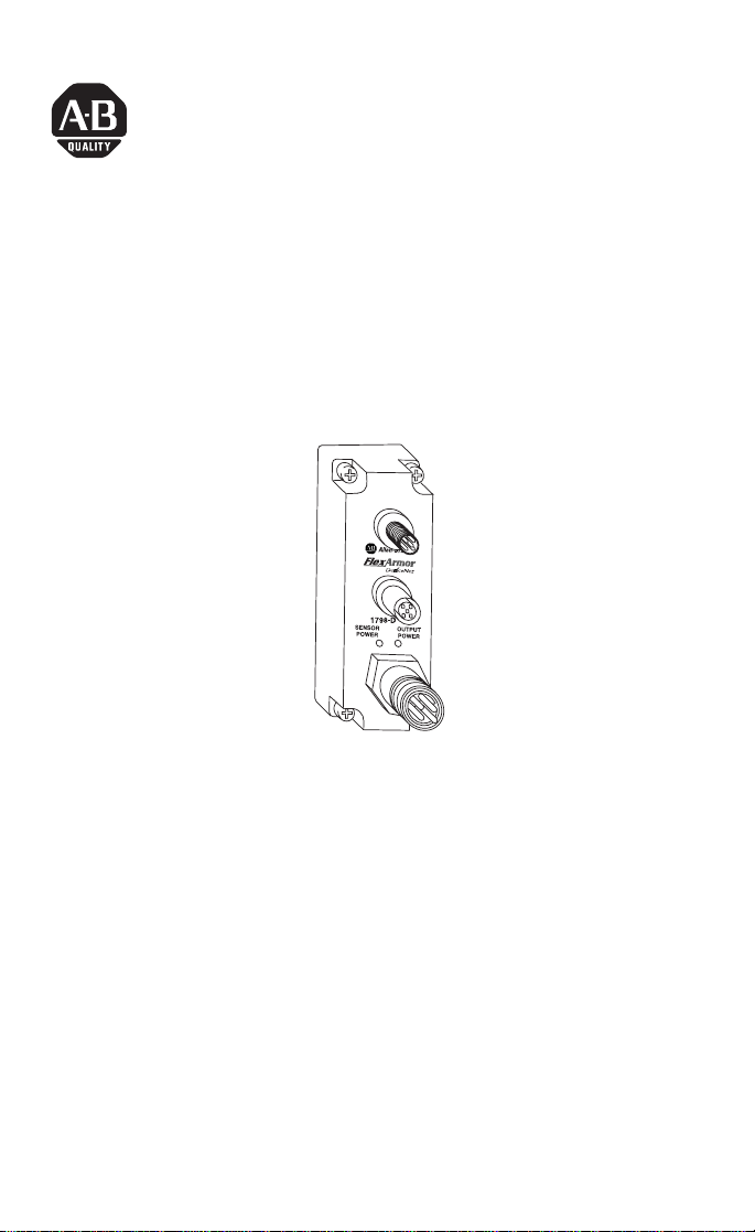
FlexArmor DeviceNet Field
Termination Plug
Catalog Number 1798-DFTP1 & -DFTP2
42534
The FlexArmor Field Termination Plug (Cat. No. 1798-DFTP1 &
-DFTP2) serves as the user connection point for the two field power
busses (sensor power and output power) as well as the DeviceNet™
network.
The connection point for the field power is capable of conducting a
maximum of 2.5A for the Sensor Power Bus and a maximum of 10A
for the Output Power Bus.
Package Contents
Your package contains:
• 1 FlexArmor DeviceNet Field Termination Plug (DFTP)
• installation instructions
(Note: Baseplates and other components are ordered and shipped
separately.)
Publication 1798-IN004A-EN-P - January 2001
Page 2

2 FlexArmor DeviceNet Field Termination Plug
European Union Directive Compliance
If this product has the CE mark it is approved for installation within
the European Union and EEA regions. It has been designed and
tested to meet the following directives.
EMC Directive
This product is tested to meet Council Directive 89/336/EEC
Electromagnetic Compatibility (EMC) and the following standards, in
whole or in part, documented in a technical construction file:
• EN 50081-2 EMC - Generic Emission Standard, Part 2 -
Industrial Environment
• EN 50082-2 EMC - Generic Immunity Standard, Part 2 -
Industrial Environment
This product is intended for use in an industrial environment.
Low Voltage Directive
This product is tested to meet Council Directive 73/23/EEC Low
Voltage, by applying the safety requirements of EN 61131-2
Programmable Controllers, Part 2 - Equipment Requirements and
Tests.
For specific information required by EN 61131-2, see the appropriate
sections in this publication, as well as the following Allen-Bradley
publications:
• Industrial Automation Wiring and Grounding Guidelines For
Noise Immunity, publication 1770-4.1
• Automation Systems Catalog, publication B113
Related Publications
For software configuration information, refer to the 1798-ADN User
Manual, publication 1798-UM001A-US-P.
Publication 1798-IN004A-EN-P - January 2001
Page 3

FlexArmor DeviceNet Field Termination Plug 3
Install Your DeviceNet Field Termination Plug
To install the module:
• Mount the DFTP
• Connect external wiring
These steps are explained in more detail in the following
procedures.
For instructions on how to mount the FlexArmor Baseplate,
refer to publication no. 1798-IN003A-EN-P.
Mount the Field Termination Plug
To mount the Field Termination Plug:
1. Place the DFTP on the left-most slot of the Baseplate.
2. Tighten the 4 screws on the DFTP.
IMPORTANT
Torque the screws to 0.5-0.7 Nm. (4.43 - 6.2 inch
pounds).
Connect External Wiring
Connect external wiring to the DFTP as shown below.
1. Connect the DeviceNet cable to the DFTP as shown.
Connect Connector Pin To
BLK Wire 3 -V
BLU Wire 5 CAN* Low
Bare Wire 1 Drain
Publication 1798-IN004A-EN-P - January 2001
Page 4

4 FlexArmor DeviceNet Field Termination Plug
Connect Connector Pin To
WHT Wire 4 CAN High
RED Wire 2 +V
*CAN=Controller Area Network
M12 Male connector (In)
3
4
5
2
1
1
4
5
3
DFTP1 DFTP2
M12 Female connector
(Daisy Chain Out)
2
42538
3
2
3
4
4
2
1
5
5
1
M18 Male
connector (In)
M18 Female
connector
(Daisy Chain Out)
42653
2. Insert connector into mating connector on the DeviceNet FTP
module.
3. Connect 24V dc power to sensor voltage for adapter and input
module power.
Connect 24V dc power to output voltage for output module
power.
4
Pin Function
1 Output Power +
2 Sensor Power +
3 Sensor Power -
4 Output Power -
3
1
2
Publication 1798-IN004A-EN-P - January 2001
Page 5

FlexArmor DeviceNet Field Termination Plug 5
Troubleshooting with the Indicators
The table describes status indicators on the Field Termination Plug.
Indicator Status
Green
Off
Power ON
Power OFF or reverse polarity
DeviceNet Field Termination Plug Specifications
Following are specifications for the DeviceNet Field Termination Plug
Voltage Rating 28.8V dc maximum
Sensor and Adapter Current 2.5A maximum
Output Current 10A maximum
Sensor/Output Voltage 10-28.8V dc
Sensor/Output Power Connector 0.875 in male
Dimensions (H x D x W) 121 mm x 36.3 mm x 42 mm
Environmental Conditions
Operational Temperature
Storage Temperature
Shock Operating
Non-operating
Vibration
Conductors See publication DN-6.7.2
Enclosure Meets IP67
Agency Certification
(When product is marked)
4.75 in. x 1.43 in. x 1.65 in.
-20 to 60°C (-4 to 140°F)
°
C (-40 to 185°F)
-40 to 85
30g peak acceleration, 11(±1) ms pulse width
50g peak acceleration, 11(±1) ms pulse width
Tested 5g @ 10-500 Hz per IEC 68-2-6
CUL listed
UL Hazardous Class 1, Division 2, Groups A, B, C, D
certified
CE marked for all applicable directives
marked for all applicable acts
N223
Publication 1798-IN004A-EN-P - January 2001
Page 6

6 FlexArmor DeviceNet Field Termination Plug
Hazardous Location Approval
The following information applies only to products marked
with Hazardous Location Approval, when operating in
hazardous locations:
Products marked “CL I, DIV 2, GP A, B, C, D” are suitable for use in
Class I Division 2 Groups A, B, C, D, Hazardous Locations and
nonhazardous locations only. Each product is supplied with markings
on the rating nameplate indicating the hazardous location
temperature code. When combining products within a system, the
most adverse temperature code (lowest “T” number) may be used to
help determine the overall temperature code of the system.
Combinations of equipment in your system are subject to
investigation by the local Authority Having Jurisdiction at the time of
installation.
WARNING
!
WARNING
EXPLOSION HAZARD -
• Do not disconnect equipment unless power
has been removed or the area is known to be
nonhazardous.
• Do not disconnect connections to this
equipment unless power has been removed
or the area is known to be nonhazardous.
Secure any external connections that mate to
this equipment by using screws, sliding
latches, threaded connectors, or other means
provided with this product.
• Substitution of components may impair
suitability for Class I, Division 2.
• If this product contains batteries, they must
only be changed in an area known to be
nonhazardous.
Use supply wires suitable for 30°C above
surrounding ambient.
!
Publication 1798-IN004A-EN-P - January 2001
Page 7

FlexArmor DeviceNet Field Termination Plug 7
WARNING
When used in a Class I, Division 2, hazardous
location, this equipment must be mounted in a
suitable enclosure with proper wiring method that
complies with the governing electrical codes.
!
Les informations suivantes ne concernent que les produits
marqués pour une utilisation en environnements dangereux :
Les produits marqués « CL I, DIV 2, GP A, B, C, D » ne conviennent
qu’à une utilisation en environnements de Classe I Division 2
Groupes A, B, C, D dangereux et non dangereux. Chaque produit est
livré avec des marquages sur sa plaque d’identification qui indiquent
le code de température pour les environnements dangereux. Lorsque
plusieurs produits sont combinés dans un système, le code de
température le plus défavorable (code de température le plus faible)
peut être utilisé pour déterminer le code de température global du
système. Les combinaisons d’équipements dans le système sont
sujettes à inspection par les autorités locales qualifiées au moment de
l’installation.
AVERTISSEMENT
!
RISQUE D’EXPLOSION -
• Couper le courant ou s’assurer que
l’environnement est classé non dangereux
avant de débrancher l’équipement.
• Couper le courant ou s’assurer que
l’environnement est classé non dangereux
avant de débrancher les connecteurs. Fixer
tous les connecteurs externes reliés à cet
équipement à l’aide de vis, loquets
coulissants, connecteurs filetés ou autres
moyens fournis avec ce produit.
• La substitution de composants peut rendre cet
équipement inadapté à une utilisation en
environnement de Classe I, Division 2.
• S’assurer que l’environnement est classé non
dangereux avant de changer les piles.
Publication 1798-IN004A-EN-P - January 2001
Page 8

AVERTISSEMENT
!
Utiliser des fils d’alimentation qui conviennent à
une température de 30°C au-dessus de la
température ambiante.
AVERTISSEMENT
Pour une utilisation en environnement de classe i,
division 2 dangereux, cet equipement doit etre
monte dans un boitier avec un cablage approprie
conforme aux normes electriques en vigueur.
!
Allen-Bradley is a registered trademark of Rockwell Automation.
DeviceNet is a trademark of Open DeviceNet Vendor Association (ODVA).
Publication 1798-IN004A-EN-P - January 2001 PN 957259-74
© 2001 Rockwell Internati onal Corporation. Printed in USA
 Loading...