

Page 1
Installation Instructions
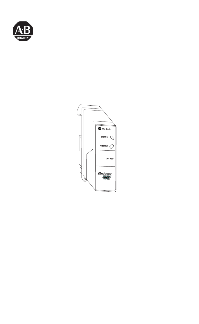
FlexArmor PROFIBUS Adapter Module
Catalog Number 1798-APB
43231
The FlexArmor PROFIBUS communication adapter (Cat. No.
1798-APB) provides the electrical interface between the network and
the FlexArmor Baseplate. You must have a Field Termination Plug
(1798-PFTP1) installed to provide the cabling interface to your
network. The Field Termination Plug also provides converter
functionality to power all of the system side electronics for the
adapter itself and the I/O modules.
Package Contents
Your package contains:
• 1 FlexArmor PROFIBUS adapter module (1798-APB)
• installation instructions
(Note: Baseplates and other components are ordered and shipped
separately.)
Publication 1798-IN011A-EN-P - March 2002
Page 2

2 FlexArmor PROFIBUS Adapter Module
ATTENTION
!
Important User Information
Because of the variety of uses for the products described in this
publication, those responsible for the application and use of these
products must satisfy themselves that all necessary steps have been
taken to assure that each application and use meets all performance
and safety requirements, including any applicable laws, regulations,
codes and standards. In no event will Allen-Bradley be responsible or
liable for indirect or consequential damage resulting from the use or
application of these products.
Any illustrations, charts, sample programs, and layout examples
shown in this publication are intended solely for purposes of
example. Since there are many variables and requirements associated
with any particular installation, Allen-Bradley does not assume
responsibility or liability (to include intellectual property liability) for
actual use based upon the examples shown in this publication.
Allen-Bradley publication SGI-1.1, Safety Guidelines for the
Application, Installation and Maintenance of Solid-State Control
(available from your local Allen-Bradley office), describes some
important differences between solid-state equipment and
electromechanical devices that should be taken into consideration
when applying products such as those described in this publication.
Reproduction of the contents of this copyrighted publication, in
whole or part, without written permission of Rockwell Automation, is
prohibited.
Throughout this publication, notes may be used to make you aware
of safety considerations. The following annotations and their
accompanying statements help you to identify a potential hazard,
avoid a potential hazard, and recognize the consequences of a
potential hazard:
Publication 1798-IN011A-EN-P - March 2002
Identifies information about practices or
circumstances that can lead to personal injury or
death, property damage, or economic loss.
Page 3

IMPORTANT
ATTENTION
!
FlexArmor PROFIBUS Adapter Module 3
Identifies information that is critical for
successful application and understanding of the
product.
Environment and Enclosure
This equipment is intended for use in a Pollution
Degree 2 industrial environment, in overvoltage
Category II applications (as defined in IEC
publication 60664-1), at altitudes up to 2000 meters
without derating.
This equipment is considered Group 1, Class A
industrial equipment according to IEC/CISPR
Publication 11. Without appropriate precautions,
there may be potential difficulties ensuring
electromagnetic compatibility in other
environments due to conducted as well as radiated
disturbance.
This equipment is supplied as "enclosed"
equipment. It should not require additional system
enclosure when used in locations consistent with
the enclosure type ratings stated in the
Specifications section of this publication.
Subsequent sections of this publication may
contain additional information regarding specific
enclosure type ratings, beyond what this product
provides, that are required to comply with certain
product safety certifications.
See NEMA Standards publication 250 and IEC
publication 60529, as applicable, for explanations
of the degrees of protection provided by different
types of enclosure. Also, see the appropriate
sections in this publication, as well as the
Allen-Bradley publication 1770-4.1 ("Industrial
Automation Wiring and Grounding Guidelines"),
for additional installation requirements pertaining
to this equipment.
Publication 1798-IN011A-EN-P - March 2002
Page 4

4 FlexArmor PROFIBUS Adapter Module
ATTENTION
!
Related Publications
• For software configuration information, refer to the FlexArmor
User Manual, publication no. 1798-UM002.
• For installation instructions for the 1798-PFTP1, see
publication no. 1798-IN005.
Preventing Electrostatic Discharge
This equipment is sensitive to electrostatic
discharge, which can cause internal damage and
affect normal operation. Follow these guidelines
when you handle this equipment:
• Touch a grounded object to discharge
potential static.
• Wear an approved grounding wriststrap.
• Do not touch connectors or pins on
component boards.
• Do not touch circuit components inside the
equipment.
• If available, use a static-safe workstation.
• When not in use, store the equipment in
appropriate static-safe packaging.
Set the Node Address on the PROFIBUS Adapter
To set the station address, adjust the switches on the back of
the adapter. The two switches are most significant digit (MSD)
and least significant digit (LSD). The switches can be set
between 00 and 99.
The rotary switches are read at adapter power-up only.
Example: Node
Address is set at 26
Publication 1798-IN011A-EN-P - March 2002
LSD
MSD
43230
Page 5

FlexArmor PROFIBUS Adapter Module 5
IMPORTANT
IMPORTANT
IMPORTANT
Install Your FlexArmor PROFIBUS Adapter Module
To install the PROFIBUS Adapter Module:
1. Hold the adapter at an angle and engage the top of the
adapter in the indention on the rear of the Baseplate.
The adapter module must be installed only in the
adapter slot, the second position from the left.
2. Press the module down flush with the panel until the locking
lever locks.
3. Screw down the module retaining screws to ensure IP67
compliance.
Torque the screws to 0.5-0.7 Nm. (4.43 - 6.2 inch
pounds).
I/O modules can be installed in any slot location
to the right of the adapter module. The adapter is
capable of addressing up to eight I/O modules.
Communicate with Your FlexArmor System
Use PROFIBUS software to configure your FlexArmor system.
Download the GSD file for this adapter from the following website:
www.ab.com/io/networks/gsd.
Publication 1798-IN011A-EN-P - March 2002
Page 6

6 FlexArmor PROFIBUS Adapter Module
Troubleshooting with the Indicators
Diagnostic indicators are located on the front of the adapter module.
They show both normal operation and error conditions in your
PROFIBUS I/O system. The indicators are:
• STATUS
• PROFIBUS
The following table describes status indicators.
STATUS Indicator
Indicator Status
OFF No power
Solid Green Normal operation
Flashing Red/OFF Recoverable fault
Solid Red Unrecoverable fault
The following table describes PROFIBUS status indicators.
PROFIBUS Indicator
Indicator Status
OFF No power or no communication
Solid Green Data is being transmitted and received
Flashing Red/OFF Recoverable fault
Solid Red Unrecoverable fault
- FlexArmor I/O module bad
- Incorrect FlexArmor I/O module installed
- Node address changed since power up
- Invalid Send Parameter data
- Invalid Check Configuration data
- Unable to communicate
Specifications
FlexArmor PROFIBUS Adapter Specifications
Network Protocol PROFIBUS-DP (EN50170)
Redundancy Not supported
Repeater Control Signal RS485 signal
Implementation Type SPC3
Publication 1798-IN011A-EN-P - March 2002
Communication of the slave with a Class 1 master
•
Communication of the slave with a Class 2 master
•
Page 7

FlexArmor PROFIBUS Adapter Module 7
FlexArmor PROFIBUS Adapter Specifications (continued)
Freeze Mode Supported
Sync Mode Supported
Auto Baud Rate Supported
Fail Safe Mode Not Supported
Station Type Slave
FMS Support Not supported
Number of nodes 100 maximum - rotary switch type node address setting
Network Length/
Communication rate
External DC Power (Input Power:)
Voltage (24V dc nom.)
Current
FlexBus (Output Power):
Voltage (5V dc nom.)
Current
Indicators 1 red/green module status
Wiring Refer to publication 1770-4.1 Programmable Controller
Isolation Type test 1250Vac rms for 60 seconds between field
Dimensions (H x D x W) 118 mm X 50 mm X 40 mm
Operational Temperature IEC 60068-2-1 (Test Ad, Operating Cold),
Storage Temperature IEC 60068-2-1 (Test Ab, Un-packaged Non-operating
Shock IEC60068-2-27 (Test Ea, Unpackaged shock):
Emissions CISPR 11:
(00-99)
9.6KBPS @ 1000m (3280ft)
19.2KBPS @ 1000m (3280ft)
45.45KBPS @ 1000m (3280ft)
93.75KBPS @ 1000m (3280ft)
187.5KBPS @ 1000m (3280ft)
500KBPS @ 400m (1312ft)
3MBPS @ 100m (328ft)
6MBPS @ 100m (328ft)
12MBPS @ 100m (328ft)
10-28.8V dc: 5% AC ripple
400 mA @ 24V dc
4.75 - 5.2V dc; 5% AC ripple
640 mA @ 5.2V dc
1 red/green network status
Wiring and Grounding Guidelines
power and PROFIBUS (I/O to logic)
4.63 in. X 1.95 in. X 1.58 in.
IEC 60068-2-2 (Test Bd, Operating Dry Heat),
IEC 60068-2-14 (Test Nb, Operating Thermal Shock):
0 to 55°C (32 to 131°F)
Cold),
IEC 60068-2-2 (Test Bb, Un-packaged Non-operating Dry
Heat),
IEC 60068-2-14 (Test Na, Un-packaged Non-operating
Thermal Shock):
–25 to 85°C (–13 to 185°F)
Operating 30g
Non-operating 50g
Group 1, Class A
Publication 1798-IN011A-EN-P - March 2002
Page 8

FlexArmor PROFIBUS Adapter Specifications (continued)
ESD Immunity IEC 61000-4-2:
4kV contact discharges
Radiated RF Immunity IEC 61000-4-3:
10V/m with 1kHz sine-wave 80%AM from 80MHz to
1000MHz
EFT/B Immunity IEC 61000-4-4:
±2kV at 5kHz on power ports
±1kV at 5kHz on signal ports
Surge Transient Immunity IEC 61000-4-5:
±1kV line-line(DM) and ±2kV line-earth(CM) on power
ports
+
1kV line-earth (CM) on shielded ports
Conducted RF Immunity IEC 61000-4-6:
10Vrms with 1kHz sine-wave 80%AM from 150kHz to
80MHz
Vibration IEC60068-2-6 (Test Fc, Operating):
5g @ 10-500Hz
Enclosure Meets IP67
Agency Certification
(When product is marked)
c-UL-us UL Listed Industrial Control Equipment,
UL UL Listed Industrial Control Equipment
CE
certified for US and Canada
1
European Union 89/336/EEC EMC Directive,
compliant with:
EN 50081-2; Industrial Emissions
EN 50082-2; Industrial Immunity
EN 61326; Meas./Control/Lab., Industrial
Requirements
EN 61000-6-2; Industrial Immunity
1
C-Tick
Australian Radiocommunications Act,
compliant with:
AS/NZS 2064; Industrial Emissions
1. See the Product Certification link at www.ab.com for Declarations of Conformity,
Certificates, and other certification details.
Allen-Bradley is a registered trademark of Rockwell Automation.
Publication 1798-IN011A-EN-P - March 2002 PN 957626-38
Copyright © 2002 Rockwell Automat ion. All rights reserved. Prin ted in the U.S.A.
 Loading...