

Page 1
FLEX Ex System
Certification
1797 Series
Reference Manual
Page 2
Important User Information
Solid state equipment has operational characteristics differing from those of
electromechanical equipment. Safety Guidelines for the Application, Installation and
Maintenance of Solid State Controls (Publication SGI-1.1 available from your local
Rockwell Automation sales office or online at http://www.ab.com/manuals/gi)
describes some important differences between solid state equipment and hard-wired
electromechanical devices. Because of this difference, and also because of the wide
variety of uses for solid state equipment, all persons responsible for applying this
equipment must satisfy themselves that each intended application of this equipment is
acceptable.
In no event will Rockwell Automation, Inc. be responsible or liable for indirect or
consequential damages resulting from the use or application of this equipment.
The examples and diagrams in this manual are included solely for illustrative purposes.
Because of the many variables and requirements associated with any particular
installation, Rockwell Automation, Inc. cannot assume responsibility or liability for
actual use based on the examples and diagrams.
No patent liability is assumed by Rockwell Automation, Inc. with respect to use of
information, circuits, equipment, or software described in this manual.
Reproduction of the contents of this manual, in whole or in part, without written
permission of Rockwell Automation, Inc. is prohibited.
Throughout this manual we may use notes to make you aware of safety considerations.
WARNING
IMPORTANT
ATTENTION
SHOCK HAZARD
BURN HAZARD
Identifies information about practices or circumstances that can
cause an explosion in a hazardous environment, which may lead
to personal injury or death, property damage, or economic loss.
Identifies information that is critical for successful application
and understanding of the product.
Identifies information about practices or circumstances that can
lead to personal injury or death, property damage, or economic
loss. Attentions help you:
• identify a hazard
• avoid a hazard
• recognize the consequence
Labels may be located on or inside the equipment to alert people
that dangerous voltage may be present.
Labels may be located on or inside the equipment to alert people
that surfaces may be dangerous temperatures.
Page 3
Summary of Changes
Changed Items
These items changed since the last printing of this FLEX Ex System
Certification Reference Manual, publication 1797-6.5.6:
Updated Information Page
1797-IE8H Section 45-2…45-4
1797-OE8H Section 48-2…48-4
To help you find new and updated information in this release of the manual,
we have included change bars as shown next to this paragraph.
1 Publication 1797-6.5.6 - June 2005
Page 4

Summary of Changes 2
Notes:
Publication 1797-6.5.6 - June 2005
Page 5

Preface
What Is Intrinsically Safe?
What are Product Certifications?
According to Article 504 of the National Electrical Code, NFPA 70, an
intrinsically safe (I/S) product is defined as one in which no spark or thermal
effect generated during normal functioning and/or during specific fault
conditions is able to ignite a given explosive atmosphere.
One example of an I/S product is FLEX Ex distributed I/O control.
A product certification is a guarantee that the product has been designed and
manufactured with the required I/S specifications and protection. Considering
the potential danger in hazardous locations, product certification is required
for all I/S products.
Three Types of Product Certifications
In this reference manual, we describe three types of product certifications and
how they relate to FLEX Ex products:
• CENELEC - European Electrotechnical Committee for
Standardization. This is the standard in all European Union
countries.
• UL and C-UL - Underwriters Laboratories (UL in the United States
and C-UL in Canada)
• FM - Factory Mutual, another available certifying body in the United
States
What are Entity Parameters?
FLEX Ex products are certified to the appropriate CENELEC, UL, C-UL and
FM standards, depending on the module.
Entity parameters provide a system of quantifying and matching safe levels for
voltage, current, inductance, and capacitance when connecting field devices
and system devices together.
FLEX Ex uses entity parameters to quantify safe levels when connecting I/O
modules to field devices. Inputs and outputs are specified with:
• open-circuit voltage (U
• short-circuit current (I
• allowed capacitance (C
• allowed inductance (L
Switched outputs are specified as if they were inputs.
Field devices using entity parameters are specified with:
• maximum input voltage (U
or Voc)
o
or Isc)
o
or Ca)
o
or La)
o
or V
i
max
)
1 Publication 1797-6.5.6 - June 2005
Page 6
Preface 2
268Ω
21V
• maximum input current (Ii or I
• maximum internal capacitance (C
• maximum internal inductance (L
In use, the sum of all the input C
C
o
and L
Also, the sum of all the Uo and Io cannot exceed the input Ui and Ii.
o.
and Li in a control loop cannot exceed the
i
max
)
)
i
)
i
The following is a short explanation of how entity-based architectures help
simplify IS system design.
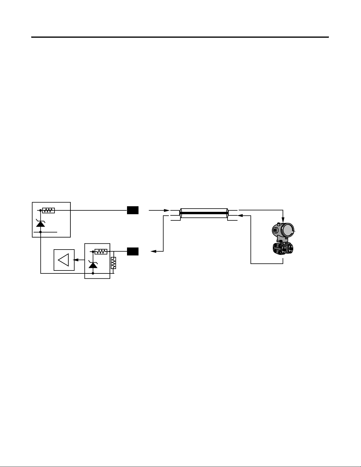
Entity Parameters Example
An output channel and the valve it will drive are illustrated in the following
figure. By comparing entity parameters, you can quickly determine the
appropriate match.
+
sig
cable length = 10m
C
<10pF/m
i
<0.5uH/m
L
i
R<0.1Ω/m
P/I transmitter
EEx ia IIC T4
U
=30V
i
=165mA
I
i
C
=22.5nF
i
=730uH
L
i
1797-IE8 Analog Input
EEx ia/ib IIB/IIC T4
U
<23.7V
o
<93.5mA
I
o
C
a
L
a
IIB
=560nF
=10mH
C
a
=2.5mH
L
a
IIC
=66nF
22Ω
Module
U
I
C
L
Module
U
<23.7V
o
I
<92.5mA
o
=66nF
C
a
L
=2.5mH
a
Total Loop
o
o
a
a
< or =
< or =
> or =
> or =
< or =
< or =
> or =
> or =
U
i
I
i
C
i
L
i
Total Loop
U
=30V
i
I
=165mA
i
=22.6nF
C
i
L
=735uH
i
=
=
=
=
=
=
=
=
Transmitter
U
i
I
i
C
i
L
i
Transmitter
U
=30V
i
I
=165mA
i
=22.5nF
C
i
L
=730uH
i
Distance Cable
++(length * C
(length * L
Distance Cable
++(10m * C
(10m * L
In this example, the combination is compatible because the valve can
withstand:
• U
• I
= 30V
i
= 165mA
i
These values are higher than what the 1797-IE8 can provide:
per length)
i
per length)
a
=10pF/m)
i
=0.5uH/m)
a
40052
Publication 1797-6.5.6 - June 2005
Page 7

• Uo= 23.7V
Preface 3
Intrinsic Safety Terminology
• I
= 93.5mA
o
In the same way, the valve is characterized by:
• C
• L
= 22.5nF
i
= 730µH
i
These values are lower than what the 1797-IE8 allows:
• C
• L
= 66nF
o
=2.5mH
o
The following sections describe key terms used in this reference manual:
Hazardous Area Designation
A hazardous area is designated as any location in which a combustible material
is or may be present in the atmosphere in sufficient concentration to produce
an ignitable mixture.
The North American method identifies these areas by Class, Division, and
Group while the IEC (CENELEC) designates these areas by Zone and Gas
Group.
Recently, North America has adopted the Zone method of identifying
hazardous locations as an option to the Division method.
Class Designation
Class identifies the type of hazardous atmosphere.
Class I Gas or vapor
Class II Dust
Class III Fiber or flying (no group designation)
Publication 1797-6.5.6 - June 2005
Page 8
Preface 4
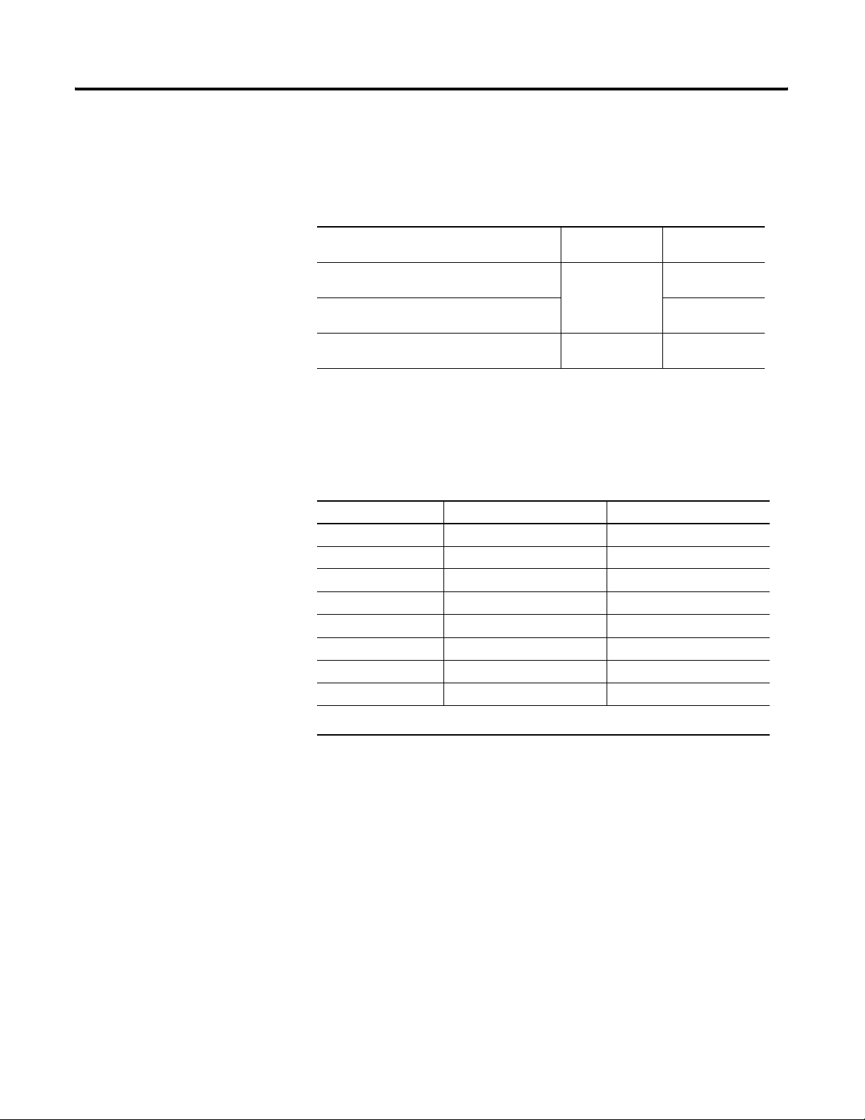
Division/Zone Designations
Division/Zone identifies the likelihood of a hazardous atmosphere being
present.
Division Method
(North America)
Ignitable mixture present continuously
(long periods)
Division 1
Ignitable mixture present intermittently
Ignitable mixture is not normally present Division 2
IEC Standard
Zone Method
Zone 0
(Zone 20-Dust)
Zone 1
(Zone 21-Dust)
Zone 2
(Zone 22-Dust)
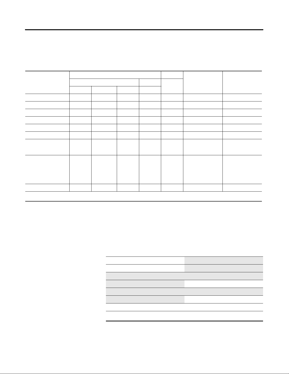
Gas/Dust Groups
Hazardous locations are grouped according to their ignition properties.
Typical Gas IEC Gas Group North American Gas Group
Acetylene IIC A
Hydrogen IIC B
Ethylene IIB C
Propane IIA D
1
Methane
Metal Dust - E
Coal Dust - F
Grain Dust - -
I
1
D
Publication 1797-6.5.6 - June 2005
1 Mining applications under jurisdiction of MSHA.
Page 9

Preface 5
Use in North American Hazardous Locations
FLEX Ex modules are rated for installation in Class I Division 1 & 2, Groups
A-D hazardous areas. They are also rated to connect to field devices that are
located in Class I, II, or III, Groups A-G hazardous areas.
If FLEX Ex components are to be installed in a Class II or III location in your
application, you can mount them in a suitable, dust-proof enclosure with the
appropriate connectors, glans, and seals. For example, a NEMA 9 enclosure
may be appropriate. The FLEX Ex modules are rated to connect to devices in
Class II or III locations.
FLEX Ex modules are rated for installation in North American Class I Zone 1
& 2, Groups IIC, IIB, & IIA hazardous areas. They are also rated to connect
to field devices that are located in North American Class I Zone 0, 1, & 2,
Groups IIC, IIB, & IIA hazardous areas.
As always, observe local code requirements when applying your FLEX Ex
application.
Use in CENELEC Hazardous Locations
FLEX Ex modules are rated for installation in European Zones 1, 2, and 22.
They are also rated to connect to field devices that are located in European
Zones 0, 1, 2, 21, and 22 hazardous areas. The FLEX Ex power supplies
(1797-PS1E and -PS2E2) are rated for use in Zones 1 and 22.
If FLEX Ex components are to be installed in a European Zone method dust
or fiber location in your application, you must mount them in an approved,
dust-proof enclosure with the appropriate connectors, glans, and seals.
Pepperl+Fuchs have three cabinets that are approved for use with FLEX Ex
components in Zone 22 applications: IVK2-ISRPI-V8LC;
IVK2-ISRPI-V8HYW; and IVK2-ISRPI-V16LC. P+F has offices in
Twinsburg, Ohio, USA, and Mannheim, Germany. See their website at
www.pepperl-fuchs.com.
As always, observe local code requirements when applying your FLEX Ex
application.
Publication 1797-6.5.6 - June 2005
Page 10
Preface 6
Methods of Protection
The following techniques are rated by methods of protection.
Symbol for Protection Method
Zone Division
Technique
Oil Immersion Ex o EEx o AEx o Ex o 1 and 2 *
Pressurization Ex p EEx p AEx p Ex p Type X, Y, Z 1 and 2 1 (X, Y) and 2 (Z)
Powder Filling Ex q EEx q AEx q Ex q 1 and 2 *
Flameproof Ex d EEx d AEx d Ex d 1 and 2
Explosionproof XP 1 and 2
Increased Safety Ex e EEx e AEx e Ex e 1 and 2 *
Intrinsic Safety
Dual Fault
Single Fault
Non-Incendive
Limited Energy
Non-Sparking
Enclosed Break
Restricted Breathing
Simplified Pressurization
Encapsulation Ex m EEx m Aex m Ex m 1 and 2 *
IEC CENELEC NEC CEC
Ex ia
Ex ib
Ex nL
Ex nV
Ex nW
Ex nR
Ex nP
EEx ia
EEx ib
EEx nL
EEx nV
EEx nW
EEx nR
EEx nP
AEx ia
AEx ib
AEx nL
AEx nV
AEx nW
AEx nR
AEx nP
Ex nW
Ex ia
IS
Ex ib
NI 2 2
Ex nL
Ex nV
Ex nR
Ex nP
Permitted Zone Permitted Division
1 and 2
0, 1, and 2
1 and 2
* These protection methods are not recognized in the Division method. However, they may be suitable for some North American Division applications.
Temperature Category
The temperature category defines the maximum surface temperature of the
o
device. Ratings are given with reference to 40
stated.
T1
T2
T2A
T2B
T2C
T2D
T3
The additional temperature categories highlighted above are for North America only.
o
C (842oF)
450
300oC (572oF)
280oC (536oF)
260oC (500oF)
230oC (446oF)
215oC (419oF)
o
200
C (392oF)
C ambient unless otherwise
T3A
T3B
T3C
T4
T4A
T5
T6
180oC (356oF)
165oC (329oF)
160oC (320oF)
135oC (275oF)
120oC (248oF)
100oC (212oF)
85oC (185oF)
Publication 1797-6.5.6 - June 2005
Page 11

Preface 7
Understanding the Layout of this Manual
CENELEC Certification Information General CENELEC Certification Information 1
This reference manual consists of three sections:
• CENELEC Certification Information
• UL, C-UL Certification Information
• FM Certification Information
TIP
The chapters in this document have been renumbered to
include additional modules. If you were referred to a
particular chapter from another document, use the tables
below to determine the correct chapter number.
CENELEC Certification Information
For Information On Refer to this Chapter
ControlNet Ex System 2
1797-TB3 FLEX Ex Terminal Base Unit 3
1797-TB3S FLEX Ex Terminal Base Unit 4
1797-IBN16 FLEX Ex 16 NAMUR Input Module 5
1797-OB4D FLEX Ex 24V dc Non-Isolated Source 4 Output Module 6
1797-IE8 FLEX Ex 8 Input Analog Module 7
1797-IE8H FLEX Ex 8 Input HART Analog Module 8
1797-IE8NF FLEX Ex 8 Input Analog Module with Noise Filter 9
1797-OE8 FLEX Ex 8 Output Analog Module 10
1797-OE8H FLEX Ex 8 Output HART Analog Module 11
1797-IRT8 FLEX Ex Thermocouple/RTD Input Module 12
1797-IJ2 FLEX Ex Frequency Input Module 13
1797-PS1E FLEX Ex Power Supply 14
1797-PS2E2 FLEX Ex Power Supply 15
1797-ACNR15 ControlNet Ex Redundant Media Adapter 16
1797-RPA ControlNet Ex Modular Repeater Adapter and
1797-RPFM Fiber Repeater Module, Medium Distance
1797-BIC Bus Isolator Module and 1797-CEC Flexbus Connector 18
1797-BCNR Redundant ControlNet Ex Barrier 19
17
Publication 1797-6.5.6 - June 2005
Page 12

Preface 8
UL, cUL Certification Information
For Information On Refer to this Chapter
UL, cUL Certification Information General UL, C-UL Certification Information 20
ControlNet Ex System 21
1797-TB3 FLEX Ex Terminal Base Unit 22
1797-TB3S FLEX Ex Terminal Base Unit 23
1797-IBN16 FLEX Ex 16 NAMUR Input Module 24
1797-OB4D FLEX Ex 24V dc Non-Isolated Source 4 Output Module 25
1797-IE8 FLEX Ex 8 Input Analog Module 26
1797-IE8H FLEX Ex 8 Input HART Analog Module 27
1797-IE8NF FLEX Ex 8 Input Analog Module with Noise Filter 28
1797-OE8 FLEX Ex 8 Output Analog Module 29
1797-OE8H FLEX Ex 8 Output HART Analog Module 30
1797-IRT8 FLEX Ex Thermocouple/RTD Input Module 31
1797-IJ2 FLEX Ex Frequency Input Module 32
1797-PS1N FLEX Ex Power Supply 33
1797-PS2N2 FLEX Ex Power Supply 34
1797-ACNR15 ControlNet Ex Redundant Media Adapter 35
1797-RPA ControlNet Ex Modular Repeater Adapter and
1797-RPFM Fiber Repeater Module, Medium Distance
1797-BCNR Redundant ControlNet Ex Barrier 37
36
Publication 1797-6.5.6 - June 2005
Page 13

FM Certification Information
For Information On Refer to this Chapter
FM Certification Information General FM Certification Information 38
ControlNet Ex System 39
1797-TB3 FLEX Ex Terminal Base Unit 40
1797-TB3S FLEX Ex Terminal Base Unit 41
1797-IBN16 FLEX Ex 16 NAMUR Input Module 42
1797-OB4D FLEX Ex 24V dc Non-Isolated Source 4 Output Module 43
1797-IE8 FLEX Ex 8 Input Analog Module 44
1797-IE8H FLEX Ex 8 Input HART Analog Module 45
1797-IE8NF FLEX Ex 8 Input Analog Module with Noise Filter 46
1797-OE8 FLEX Ex 8 Output Analog Module 47
1797-OE8H FLEX Ex 8 Output HART Analog Module 48
1797-IRT8 FLEX Ex Thermocouple/RTD Input Module 49
1797-IJ2 FLEX Ex Frequency Input Module 50
Preface 9
1797-PS1N FLEX Ex Power Supply 51
1797-PS2N2 FLEX Ex Power Supply 52
1797-ACNR15 ControlNet Ex Redundant Media Adapter 53
1797-RPA ControlNet Ex Modular Repeater Adapter and
1797-RPFM Fiber Repeater Module, Medium Distance
1797-BIC Bus Isolator Module and 1797-CEC Flexbus Connector 55
54
Publication 1797-6.5.6 - June 2005
Page 14

Preface 10
Notes:
Publication 1797-6.5.6 - June 2005
Page 15

General CENELEC Certification
Information
ControlNet Ex System
Table of Contents
CENELEC Information
Chapter 1
General Installation . . . . . . . . . . . . . . . . . . . . . . . . . . . . . . . . . . . . . . . 1-1
Installation in Zone 1. . . . . . . . . . . . . . . . . . . . . . . . . . . . . . . . . . . . . . 1-2
Installation in Zone 22. . . . . . . . . . . . . . . . . . . . . . . . . . . . . . . . . . . . . 1-2
Electrostatic Charge . . . . . . . . . . . . . . . . . . . . . . . . . . . . . . . . . . . . . . . 1-2
European Community Directive Compliance . . . . . . . . . . . . . . . . . . 1-2
EMC Directive. . . . . . . . . . . . . . . . . . . . . . . . . . . . . . . . . . . . . . . . 1-2
LVD Directive . . . . . . . . . . . . . . . . . . . . . . . . . . . . . . . . . . . . . . . . 1-2
ATEX Directive. . . . . . . . . . . . . . . . . . . . . . . . . . . . . . . . . . . . . . . 1-3
Repair . . . . . . . . . . . . . . . . . . . . . . . . . . . . . . . . . . . . . . . . . . . . . . . . . . 1-3
Attention: Avoid electrostatic charge.. . . . . . . . . . . . . . . . . . . . . . 1-3
About Zone 22 Junction Boxes (Cabinets). . . . . . . . . . . . . . . . . . . . . 1-4
Chapter 2
ControlNet Ex System Diagram . . . . . . . . . . . . . . . . . . . . . . . . . . . . . 2-2
Describing the ControlNet Ex System Diagram . . . . . . . . . . . . . . . . 2-3
Certified Equivalent ControlNet Ex System Diagram Items . . . 2-4
Installation in Zone 1. . . . . . . . . . . . . . . . . . . . . . . . . . . . . . . . . . . . . . 2-5
Installation in Zone 22. . . . . . . . . . . . . . . . . . . . . . . . . . . . . . . . . . . . . 2-5
Electrostatic Charge . . . . . . . . . . . . . . . . . . . . . . . . . . . . . . . . . . . . . . . 2-5
Repair . . . . . . . . . . . . . . . . . . . . . . . . . . . . . . . . . . . . . . . . . . . . . . . . . . 2-5
Attention: Avoid electrostatic charge.. . . . . . . . . . . . . . . . . . . . . . 2-5
General Specifications . . . . . . . . . . . . . . . . . . . . . . . . . . . . . . . . . . . . . 2-6
Chapter 3
1797-TB3 FLEX Ex
Terminal Base Unit
General Information . . . . . . . . . . . . . . . . . . . . . . . . . . . . . . . . . . . . . . 3-1
Module Installation . . . . . . . . . . . . . . . . . . . . . . . . . . . . . . . . . . . . . . . 3-1
Inputs . . . . . . . . . . . . . . . . . . . . . . . . . . . . . . . . . . . . . . . . . . . . . . . . . . 3-2
Description . . . . . . . . . . . . . . . . . . . . . . . . . . . . . . . . . . . . . . . . . . . . . . 3-2
Intrinsically Safe Specifications . . . . . . . . . . . . . . . . . . . . . . . . . . . . . . 3-3
Chapter 4
1797-TB3S FLEX Ex
Terminal Base Unit
i Publication 1797-6.5.6 - June 2005
General Information . . . . . . . . . . . . . . . . . . . . . . . . . . . . . . . . . . . . . . 4-1
Module Installation . . . . . . . . . . . . . . . . . . . . . . . . . . . . . . . . . . . . . . . 4-1
Inputs . . . . . . . . . . . . . . . . . . . . . . . . . . . . . . . . . . . . . . . . . . . . . . . . . . 4-2
Description . . . . . . . . . . . . . . . . . . . . . . . . . . . . . . . . . . . . . . . . . . . . . . 4-2
Intrinsically Safe Specifications . . . . . . . . . . . . . . . . . . . . . . . . . . . . . . 4-3
Page 16

ii
1797-IBN16 FLEX Ex 16 NAMUR
Input Module
1797-OB4D FLEX Ex 24V dc
Non-Isolated Source 4 Output
Module
1797-IE8 FLEX Ex 8 Input Analog
Module
Chapter 5
General Information . . . . . . . . . . . . . . . . . . . . . . . . . . . . . . . . . . . . . . 5-1
Module Installation . . . . . . . . . . . . . . . . . . . . . . . . . . . . . . . . . . . . . . . 5-1
Inputs . . . . . . . . . . . . . . . . . . . . . . . . . . . . . . . . . . . . . . . . . . . . . . . . . . 5-1
Wiring to a 1797-TB3 or -TB3S Terminal Base Unit. . . . . . . . . . . . . 5-2
Intrinsically Safe Specifications . . . . . . . . . . . . . . . . . . . . . . . . . . . . . . 5-2
CE/CENELEC I/O Entity Parameters (Each Channel) . . . . . . . . . 5-3
Chapter 6
General Information . . . . . . . . . . . . . . . . . . . . . . . . . . . . . . . . . . . . . . 6-1
Module Installation . . . . . . . . . . . . . . . . . . . . . . . . . . . . . . . . . . . . . . . 6-1
Outputs. . . . . . . . . . . . . . . . . . . . . . . . . . . . . . . . . . . . . . . . . . . . . . . . . 6-1
Wiring to a 1797-TB3 or -TB3S Terminal Base Unit. . . . . . . . . . . . . 6-1
Intrinsically Safe Specifications . . . . . . . . . . . . . . . . . . . . . . . . . . . . . . 6-2
CE/CENELEC I/O Entity Parameters. . . . . . . . . . . . . . . . . . . . . . . 6-2
Chapter 7
General Information . . . . . . . . . . . . . . . . . . . . . . . . . . . . . . . . . . . . . . 7-1
Module Installation . . . . . . . . . . . . . . . . . . . . . . . . . . . . . . . . . . . . . . . 7-1
Inputs . . . . . . . . . . . . . . . . . . . . . . . . . . . . . . . . . . . . . . . . . . . . . . . . . . 7-1
Wiring to a 1797-TB3 or -TB3S Terminal Base Unit. . . . . . . . . . . . . 7-2
Intrinsically Safe Specifications . . . . . . . . . . . . . . . . . . . . . . . . . . . . . . 7-2
CE/CENELEC I/O Entity Parameters. . . . . . . . . . . . . . . . . . . . . . . 7-3
1797-IE8H FLEX Ex 8 Input HART
Analog Module
1797-IE8NF FLEX Ex 8 Input
Analog Module with Noise Filter
Chapter 8
General Information . . . . . . . . . . . . . . . . . . . . . . . . . . . . . . . . . . . . . . 8-1
Module Installation . . . . . . . . . . . . . . . . . . . . . . . . . . . . . . . . . . . . . . . 8-1
Inputs . . . . . . . . . . . . . . . . . . . . . . . . . . . . . . . . . . . . . . . . . . . . . . . . . . 8-1
Wiring to a 1797-TB3 or -TB3S Terminal Base Unit. . . . . . . . . . . . . 8-2
Intrinsically Safe Specifications . . . . . . . . . . . . . . . . . . . . . . . . . . . . . . 8-2
CE/CENELEC I/O Entity Parameters. . . . . . . . . . . . . . . . . . . . . . . 8-3
Chapter 9
General Information . . . . . . . . . . . . . . . . . . . . . . . . . . . . . . . . . . . . . . 9-1
Module Installation . . . . . . . . . . . . . . . . . . . . . . . . . . . . . . . . . . . . . . . 9-1
Inputs . . . . . . . . . . . . . . . . . . . . . . . . . . . . . . . . . . . . . . . . . . . . . . . . . . 9-1
Wiring to a 1797-TB3 or -TB3S Terminal Base Unit. . . . . . . . . . . . . 9-2
Intrinsically Safe Specifications . . . . . . . . . . . . . . . . . . . . . . . . . . . . . . 9-2
CE/CENELEC I/O Entity Parameters. . . . . . . . . . . . . . . . . . . . . . . 9-3
Publication 1797-6.5.6 - June 2005
Page 17

1797-OE8 FLEX Ex 8 Output Analog
Module
1797-OE8H FLEX Ex 8 Output HART
Analog Module
1797-IRT8 FLEX Ex
Thermocouple/RTD Input Module
iii
Chapter 10
General Information . . . . . . . . . . . . . . . . . . . . . . . . . . . . . . . . . . . . . 10-1
Module Installation . . . . . . . . . . . . . . . . . . . . . . . . . . . . . . . . . . . . . . 10-1
Outputs. . . . . . . . . . . . . . . . . . . . . . . . . . . . . . . . . . . . . . . . . . . . . . . . 10-1
Wiring to a 1797-TB3 or -TB3S Terminal Base Unit. . . . . . . . . . . . 10-1
General Specifications . . . . . . . . . . . . . . . . . . . . . . . . . . . . . . . . . . . . 10-2
CE, CENELEC I/O Entity Parameters. . . . . . . . . . . . . . . . . . . . . . 10-2
Chapter 11
General Information . . . . . . . . . . . . . . . . . . . . . . . . . . . . . . . . . . . . . 11-1
Module Installation . . . . . . . . . . . . . . . . . . . . . . . . . . . . . . . . . . . . . . 11-1
Outputs. . . . . . . . . . . . . . . . . . . . . . . . . . . . . . . . . . . . . . . . . . . . . . . . 11-1
Wiring to a 1797-TB3 or -TB3S Terminal Base Unit. . . . . . . . . . . . 11-1
General Specifications . . . . . . . . . . . . . . . . . . . . . . . . . . . . . . . . . . . . 11-2
CE, CENELEC I/O Entity Parameters. . . . . . . . . . . . . . . . . . . . . . 11-2
Chapter 12
General Information . . . . . . . . . . . . . . . . . . . . . . . . . . . . . . . . . . . . . 12-1
Module Installation . . . . . . . . . . . . . . . . . . . . . . . . . . . . . . . . . . . . . . 12-1
Inputs . . . . . . . . . . . . . . . . . . . . . . . . . . . . . . . . . . . . . . . . . . . . . . . . . 12-1
Wiring to a 1797-TB3 or -TB3S Terminal Base Unit. . . . . . . . . . . . 12-2
Intrinsically Safe Specifications . . . . . . . . . . . . . . . . . . . . . . . . . . . . . 12-2
CE/CENELEC I/O Entity Parameters. . . . . . . . . . . . . . . . . . . . . . 12-3
1797-IJ2 FLEX Ex Frequency Input
Module
1797-PS1E FLEX Ex Power Supply
Chapter 13
General Information . . . . . . . . . . . . . . . . . . . . . . . . . . . . . . . . . . . . . 13-1
Module Installation . . . . . . . . . . . . . . . . . . . . . . . . . . . . . . . . . . . . . . 13-1
Inputs . . . . . . . . . . . . . . . . . . . . . . . . . . . . . . . . . . . . . . . . . . . . . . . . . 13-1
Wiring to a 1797-TB3 or -TB3S Terminal Base Unit. . . . . . . . . . . . 13-2
Intrinsically Safe Specifications . . . . . . . . . . . . . . . . . . . . . . . . . . . . . 13-2
CE/CENELEC Input I/O Entity Parameters. . . . . . . . . . . . . . . . . 13-3
Channel 0 Frequency Input. . . . . . . . . . . . . . . . . . . . . . . . . . . . . 13-3
Channel 1 Frequency Input. . . . . . . . . . . . . . . . . . . . . . . . . . . . . 13-4
Channel 0 Gate Input . . . . . . . . . . . . . . . . . . . . . . . . . . . . . . . . . 13-5
Channel 1 Gate Input . . . . . . . . . . . . . . . . . . . . . . . . . . . . . . . . . 13-5
Relay Outputs. . . . . . . . . . . . . . . . . . . . . . . . . . . . . . . . . . . . . . . . . . . 13-6
Chapter 14
Installation in Zone 1. . . . . . . . . . . . . . . . . . . . . . . . . . . . . . . . . . . . . 14-1
Installation in Zone 22. . . . . . . . . . . . . . . . . . . . . . . . . . . . . . . . . . . . 14-1
Outputs. . . . . . . . . . . . . . . . . . . . . . . . . . . . . . . . . . . . . . . . . . . . . . . . 14-1
Typical Wiring Configurations. . . . . . . . . . . . . . . . . . . . . . . . . . . . . . 14-2
Intrinsically Safe Specifications . . . . . . . . . . . . . . . . . . . . . . . . . . . . . 14-2
Publication 1797-6.5.6 - June 2005
Page 18

iv
1797-PS2E2 FLEX Ex Power Supply
1797-ACNR15 ControlNet Ex
Redundant Media Adapter
1797-RPA ControlNet Ex Modular
Repeater Adapter and 1797-RPFM
Fiber Repeater Module, Medium
Distance
1797-BIC Bus Isolator Module and
1797-CEC Flexbus Connector
Chapter 15
Installation in Zone 1. . . . . . . . . . . . . . . . . . . . . . . . . . . . . . . . . . . . . 15-1
Installation in Zone 22. . . . . . . . . . . . . . . . . . . . . . . . . . . . . . . . . . . . 15-1
Outputs. . . . . . . . . . . . . . . . . . . . . . . . . . . . . . . . . . . . . . . . . . . . . . . . 15-1
Typical Wiring Configurations. . . . . . . . . . . . . . . . . . . . . . . . . . . . . . 15-2
Intrinsically Safe Specifications . . . . . . . . . . . . . . . . . . . . . . . . . . . . . 15-2
Chapter 16
Module Installation . . . . . . . . . . . . . . . . . . . . . . . . . . . . . . . . . . . . . . 16-1
Inputs/Outputs . . . . . . . . . . . . . . . . . . . . . . . . . . . . . . . . . . . . . . . . . 16-1
Intrinsically Safe Specifications . . . . . . . . . . . . . . . . . . . . . . . . . . . . . 16-2
Chapter 17
Module Installation . . . . . . . . . . . . . . . . . . . . . . . . . . . . . . . . . . . . . . 17-1
Inputs/Outputs . . . . . . . . . . . . . . . . . . . . . . . . . . . . . . . . . . . . . . . . . 17-1
Intrinsically Safe Specifications . . . . . . . . . . . . . . . . . . . . . . . . . . . . . 17-2
Chapter 18
General Installation . . . . . . . . . . . . . . . . . . . . . . . . . . . . . . . . . . . . . . 18-1
Inputs/Outputs . . . . . . . . . . . . . . . . . . . . . . . . . . . . . . . . . . . . . . . . . 18-2
Intrinsically Safe Specifications . . . . . . . . . . . . . . . . . . . . . . . . . . . . . 18-3
1797-BCNR Redundant ControlNet
Ex Barrier
Chapter 19
Description . . . . . . . . . . . . . . . . . . . . . . . . . . . . . . . . . . . . . . . . . . . . . 19-1
Inputs/Outputs . . . . . . . . . . . . . . . . . . . . . . . . . . . . . . . . . . . . . . . . . 19-1
Intrinsically Safe Specifications . . . . . . . . . . . . . . . . . . . . . . . . . . . . . 19-2
Repair . . . . . . . . . . . . . . . . . . . . . . . . . . . . . . . . . . . . . . . . . . . . . . . . . 19-2
Publication 1797-6.5.6 - June 2005
Page 19

General UL, C-UL Certification
Information
ControlNet Ex System
v
UL, C-UL Information
Chapter 20
Module Installation . . . . . . . . . . . . . . . . . . . . . . . . . . . . . . . . . . . . . . 20-1
Installation in Division 1/
Zone 1. . . . . . . . . . . . . . . . . . . . . . . . . . . . . . . . . . . . . . . . . . . . . . . . . 20-2
Electrostatic Charge . . . . . . . . . . . . . . . . . . . . . . . . . . . . . . . . . . . . . . 20-2
UL, C-UL I/O Entity Parameters. . . . . . . . . . . . . . . . . . . . . . . . . . . 20-2
Repair . . . . . . . . . . . . . . . . . . . . . . . . . . . . . . . . . . . . . . . . . . . . . . . . . 20-2
Attention: Avoid electrostatic charge.. . . . . . . . . . . . . . . . . . . . . 20-2
Chapter 21
ControlNet Ex System Diagram . . . . . . . . . . . . . . . . . . . . . . . . . . . . 21-2
Describing the ControlNet Ex System Diagram . . . . . . . . . . . . . . . 21-3
Certified Equivalent ControlNet Ex System Diagram Items . . 21-4
Installation in Division 1/
Zone 1. . . . . . . . . . . . . . . . . . . . . . . . . . . . . . . . . . . . . . . . . . . . . . . . . 21-5
Electrostatic Charge . . . . . . . . . . . . . . . . . . . . . . . . . . . . . . . . . . . . . . 21-6
Repair . . . . . . . . . . . . . . . . . . . . . . . . . . . . . . . . . . . . . . . . . . . . . . . . . 21-6
Attention: Avoid electrostatic charge.. . . . . . . . . . . . . . . . . . . . . 21-6
1797-TB3 FLEX Ex
Terminal Base Unit
1797-TB3S FLEX Ex
Terminal Base Unit
Chapter 22
General Information . . . . . . . . . . . . . . . . . . . . . . . . . . . . . . . . . . . . . 22-1
Module Installation . . . . . . . . . . . . . . . . . . . . . . . . . . . . . . . . . . . . . . 22-1
Installation in Division 1/
Zone 1. . . . . . . . . . . . . . . . . . . . . . . . . . . . . . . . . . . . . . . . . . . . . . . . . 22-1
Inputs . . . . . . . . . . . . . . . . . . . . . . . . . . . . . . . . . . . . . . . . . . . . . . . . . 22-2
Description . . . . . . . . . . . . . . . . . . . . . . . . . . . . . . . . . . . . . . . . . . . . . 22-2
Intrinsically Safe Specifications . . . . . . . . . . . . . . . . . . . . . . . . . . . . . 22-3
Chapter 23
General Information . . . . . . . . . . . . . . . . . . . . . . . . . . . . . . . . . . . . . 23-1
Module Installation . . . . . . . . . . . . . . . . . . . . . . . . . . . . . . . . . . . . . . 23-1
Installation in Division 1/
Zone 1. . . . . . . . . . . . . . . . . . . . . . . . . . . . . . . . . . . . . . . . . . . . . . . . . 23-1
Inputs . . . . . . . . . . . . . . . . . . . . . . . . . . . . . . . . . . . . . . . . . . . . . . . . . 23-2
Description . . . . . . . . . . . . . . . . . . . . . . . . . . . . . . . . . . . . . . . . . . . . . 23-2
Intrinsically Safe Specifications . . . . . . . . . . . . . . . . . . . . . . . . . . . . . 23-3
Publication 1797-6.5.6 - June 2005
Page 20

vi
1797-IBN16 FLEX Ex 16 NAMUR
Input Module
1797-OB4D FLEX Ex 24V dc
Non-Isolated Source 4 Output
Module
Chapter 24
General Information . . . . . . . . . . . . . . . . . . . . . . . . . . . . . . . . . . . . . 24-1
Module Installation . . . . . . . . . . . . . . . . . . . . . . . . . . . . . . . . . . . . . . 24-1
Inputs . . . . . . . . . . . . . . . . . . . . . . . . . . . . . . . . . . . . . . . . . . . . . . . . . 24-1
Wiring to a 1797-TB3 or -TB3S Terminal Base Unit. . . . . . . . . . . . 24-1
Intrinsically Safe Specifications . . . . . . . . . . . . . . . . . . . . . . . . . . . . . 24-2
UL, C-UL I/O Entity Parameters. . . . . . . . . . . . . . . . . . . . . . . . . . . 24-3
Table 1: Entity Values for Field Device Connections . . . . . . . . 24-3
Table 2: Flexbus Entity Values Which are Allowed for the Next
FLEX Ex I/O Module . . . . . . . . . . . . . . . . . . . . . . . . . . . . . . . . 24-4
Table 3: Flexbus Entity Values for this Module. . . . . . . . . . . . . 24-4
Chapter 25
General Information . . . . . . . . . . . . . . . . . . . . . . . . . . . . . . . . . . . . . 25-1
Module Installation . . . . . . . . . . . . . . . . . . . . . . . . . . . . . . . . . . . . . . 25-1
Outputs. . . . . . . . . . . . . . . . . . . . . . . . . . . . . . . . . . . . . . . . . . . . . . . . 25-1
Wiring to a 1797-TB3 or -TB3S Terminal Base Unit. . . . . . . . . . . . 25-1
Intrinsically Safe Specifications . . . . . . . . . . . . . . . . . . . . . . . . . . . . . 25-2
UL, C-UL I/O Entity Parameters. . . . . . . . . . . . . . . . . . . . . . . . . . . 25-2
Table 1: Entity Values for Field Device Connections . . . . . . . . 25-3
Table 2: Flexbus Entity Values Which are Allowed for the Next
FLEX Ex I/O Module . . . . . . . . . . . . . . . . . . . . . . . . . . . . . . . . 25-4
Table 3: Flexbus Entity Values for this Module. . . . . . . . . . . . . 25-4
1797-IE8 FLEX Ex 8 Input Analog
Module
Chapter 26
General Information . . . . . . . . . . . . . . . . . . . . . . . . . . . . . . . . . . . . . 26-1
Module Installation . . . . . . . . . . . . . . . . . . . . . . . . . . . . . . . . . . . . . . 26-1
Inputs . . . . . . . . . . . . . . . . . . . . . . . . . . . . . . . . . . . . . . . . . . . . . . . . . 26-1
Wiring to a 1797-TB3 or -TB3S Terminal Base Unit. . . . . . . . . . . . 26-1
Intrinsically Safe Specifications . . . . . . . . . . . . . . . . . . . . . . . . . . . . . 26-2
UL, C-UL I/O Entity Parameters. . . . . . . . . . . . . . . . . . . . . . . . . . . 26-3
Table 1: Entity Values for Field Device Connections . . . . . . . . 26-3
Table 2: Flexbus Entity Values Which are Allowed for the Next
FLEX Ex I/O Module . . . . . . . . . . . . . . . . . . . . . . . . . . . . . . . . 26-4
Table 3: Flexbus Entity Values for this Module. . . . . . . . . . . . . 26-4
Publication 1797-6.5.6 - June 2005
Page 21

1797-IE8H FLEX Ex 8 Input HART
Analog Module
1797-IE8NF FLEX Ex 8 Input
Analog Module with Noise Filter
vii
Chapter 27
General Information . . . . . . . . . . . . . . . . . . . . . . . . . . . . . . . . . . . . . 27-1
Module Installation . . . . . . . . . . . . . . . . . . . . . . . . . . . . . . . . . . . . . . 27-1
Inputs . . . . . . . . . . . . . . . . . . . . . . . . . . . . . . . . . . . . . . . . . . . . . . . . . 27-1
Wiring to a 1797-TB3 or -TB3S Terminal Base Unit. . . . . . . . . . . . 27-1
Intrinsically Safe Specifications . . . . . . . . . . . . . . . . . . . . . . . . . . . . . 27-2
UL, C-UL I/O Entity Parameters. . . . . . . . . . . . . . . . . . . . . . . . . . . 27-3
Table 1: Entity Values for Field Device Connections . . . . . . . . 27-3
Table 2: Flexbus Entity Values Which are Allowed for the Next
FLEX Ex I/O Module . . . . . . . . . . . . . . . . . . . . . . . . . . . . . . . . 27-4
Table 3: Flexbus Entity Values for this Module. . . . . . . . . . . . . 27-4
Chapter 28
General Information . . . . . . . . . . . . . . . . . . . . . . . . . . . . . . . . . . . . . 28-1
Module Installation . . . . . . . . . . . . . . . . . . . . . . . . . . . . . . . . . . . . . . 28-1
Inputs . . . . . . . . . . . . . . . . . . . . . . . . . . . . . . . . . . . . . . . . . . . . . . . . . 28-1
Wiring to a 1797-TB3 or -TB3S Terminal Base Unit. . . . . . . . . . . . 28-1
Intrinsically Safe Specifications . . . . . . . . . . . . . . . . . . . . . . . . . . . . . 28-2
UL, C-UL I/O Entity Parameters. . . . . . . . . . . . . . . . . . . . . . . . . . . 28-3
Table 1: Entity Values for Field Device Connections . . . . . . . . 28-3
Table 2: Flexbus Entity Values Which are Allowed for the Next
FLEX Ex I/O Module . . . . . . . . . . . . . . . . . . . . . . . . . . . . . . . . 28-4
Table 3: Flexbus Entity Values for this Module. . . . . . . . . . . . . 28-4
1797-OE8 FLEX Ex 8 Output Analog
Module
Chapter 29
General Information . . . . . . . . . . . . . . . . . . . . . . . . . . . . . . . . . . . . . 29-1
Module Installation . . . . . . . . . . . . . . . . . . . . . . . . . . . . . . . . . . . . . . 29-1
Outputs. . . . . . . . . . . . . . . . . . . . . . . . . . . . . . . . . . . . . . . . . . . . . . . . 29-1
Wiring to a 1797-TB3 or -TB3S Terminal Base Unit. . . . . . . . . . . . 29-1
Intrinsically Safe Specifications . . . . . . . . . . . . . . . . . . . . . . . . . . . . . 29-2
UL, C-UL I/O Entity Parameters. . . . . . . . . . . . . . . . . . . . . . . . . . . 29-2
Table 1: Entity Values for Field Device Connections . . . . . . . . 29-2
Table 2: Flexbus Entity Values Which are Allowed for the Next
FLEX Ex I/O Module . . . . . . . . . . . . . . . . . . . . . . . . . . . . . . . . 29-4
Table 3: Flexbus Entity Values for this Module. . . . . . . . . . . . . 29-4
Publication 1797-6.5.6 - June 2005
Page 22

viii
1797-OE8H FLEX Ex 8 Output HART
Analog Module
1797-IRT8 FLEX Ex
Thermocouple/RTD Input Module
Chapter 30
General Information . . . . . . . . . . . . . . . . . . . . . . . . . . . . . . . . . . . . . 30-1
Module Installation . . . . . . . . . . . . . . . . . . . . . . . . . . . . . . . . . . . . . . 30-1
Outputs. . . . . . . . . . . . . . . . . . . . . . . . . . . . . . . . . . . . . . . . . . . . . . . . 30-1
Wiring to a 1797-TB3 or -TB3S Terminal Base Unit. . . . . . . . . . . . 30-1
Intrinsically Safe Specifications . . . . . . . . . . . . . . . . . . . . . . . . . . . . . 30-2
UL, C-UL I/O Entity Parameters. . . . . . . . . . . . . . . . . . . . . . . . . . . 30-2
Table 1: Entity Values for Field Device Connections . . . . . . . . 30-2
Table 2: Flexbus Entity Values Which are Allowed for the Next
FLEX Ex I/O Module . . . . . . . . . . . . . . . . . . . . . . . . . . . . . . . . 30-4
Table 3: Flexbus Entity Values for this Module. . . . . . . . . . . . . 30-4
Chapter 31
General Information . . . . . . . . . . . . . . . . . . . . . . . . . . . . . . . . . . . . . 31-1
Module Installation . . . . . . . . . . . . . . . . . . . . . . . . . . . . . . . . . . . . . . 31-1
Inputs . . . . . . . . . . . . . . . . . . . . . . . . . . . . . . . . . . . . . . . . . . . . . . . . . 31-1
Wiring to a 1797-TB3 or -TB3S Terminal Base Unit. . . . . . . . . . . . 31-2
Intrinsically Safe Specifications . . . . . . . . . . . . . . . . . . . . . . . . . . . . . 31-2
UL, C-UL I/O Entity Parameters. . . . . . . . . . . . . . . . . . . . . . . . . . . 31-3
Table 1: Entity Values for Field Device Connections . . . . . . . . 31-3
Table 2: Flexbus Entity Values Which are Allowed for the Next
FLEX Ex I/O Module . . . . . . . . . . . . . . . . . . . . . . . . . . . . . . . . 31-5
Table 3: Flexbus Entity Values for this Module. . . . . . . . . . . . . 31-5
1797-IJ2 FLEX Ex Frequency Input
Module
1797-PS1N FLEX Ex Power Supply
Chapter 32
General Information . . . . . . . . . . . . . . . . . . . . . . . . . . . . . . . . . . . . . 32-1
Module Installation . . . . . . . . . . . . . . . . . . . . . . . . . . . . . . . . . . . . . . 32-1
Inputs . . . . . . . . . . . . . . . . . . . . . . . . . . . . . . . . . . . . . . . . . . . . . . . . . 32-1
Wiring to a 1797-TB3 or -TB3S Terminal Base Unit. . . . . . . . . . . . 32-1
Intrinsically Safe Specifications . . . . . . . . . . . . . . . . . . . . . . . . . . . . . 32-2
UL, C-UL I/O Entity Parameters. . . . . . . . . . . . . . . . . . . . . . . . . . . 32-2
Table 1: Entity Values for Field Device Connections . . . . . . . . 32-3
Table 2: Flexbus Entity Values Which are Allowed for the Next
FLEX Ex I/O Module . . . . . . . . . . . . . . . . . . . . . . . . . . . . . . . . 32-4
Table 3: Flexbus Entity Values for this Module. . . . . . . . . . . . . 32-4
Chapter 33
Installation in Division 1/
Zone 1. . . . . . . . . . . . . . . . . . . . . . . . . . . . . . . . . . . . . . . . . . . . . . . . . 33-1
Outputs. . . . . . . . . . . . . . . . . . . . . . . . . . . . . . . . . . . . . . . . . . . . . . . . 33-1
Typical Wiring Configurations. . . . . . . . . . . . . . . . . . . . . . . . . . . . . . 33-1
Intrinsically Safe Specifications . . . . . . . . . . . . . . . . . . . . . . . . . . . . . 33-2
UL, C-UL I/O Entity Parameters. . . . . . . . . . . . . . . . . . . . . . . . . . . 33-2
Table 1: Entity Values for Field Device Connections . . . . . . . . 33-2
Publication 1797-6.5.6 - June 2005
Page 23

1797-PS2N2 FLEX Ex
Power Supply
1797-ACNR15 ControlNet Ex
Redundant Media Adapter
ix
Chapter 34
Installation in Division 1/
Zone 1. . . . . . . . . . . . . . . . . . . . . . . . . . . . . . . . . . . . . . . . . . . . . . . . . 34-1
Outputs. . . . . . . . . . . . . . . . . . . . . . . . . . . . . . . . . . . . . . . . . . . . . . . . 34-1
Typical Wiring Configurations. . . . . . . . . . . . . . . . . . . . . . . . . . . . . . 34-1
Intrinsically Safe Specifications . . . . . . . . . . . . . . . . . . . . . . . . . . . . . 34-2
UL, C-UL I/O Entity Parameters. . . . . . . . . . . . . . . . . . . . . . . . . . . 34-2
Table 1: Entity Values for Field Device Connections . . . . . . . . 34-2
Chapter 35
Module Installation . . . . . . . . . . . . . . . . . . . . . . . . . . . . . . . . . . . . . . 35-1
Inputs/Outputs . . . . . . . . . . . . . . . . . . . . . . . . . . . . . . . . . . . . . . . . . 35-1
General Specifications . . . . . . . . . . . . . . . . . . . . . . . . . . . . . . . . . . . . 35-1
UL, cUL Entity Parameters and Requirements . . . . . . . . . . . . . . . . 35-2
UL, C-UL I/O Entity Parameters and Requirements . . . . . . . . 35-2
Table 2: Flexbus Entity Values Which are Allowed for the Next
FLEX Ex I/O Module . . . . . . . . . . . . . . . . . . . . . . . . . . . . . . . . 35-2
1797-RPA ControlNet Ex Modular
Repeater Adapter and 1797-RPFM
Fiber Repeater Module, Medium
Distance
1797-BCNR Redundant ControlNet
Ex Barrier
Chapter 36
Module Installation . . . . . . . . . . . . . . . . . . . . . . . . . . . . . . . . . . . . . . 36-1
Inputs/Outputs . . . . . . . . . . . . . . . . . . . . . . . . . . . . . . . . . . . . . . . . . 36-1
Intrinsically Safe Specifications . . . . . . . . . . . . . . . . . . . . . . . . . . . . . 36-2
UL, cUL Entity Parameters and Requirements . . . . . . . . . . . . . . . . 36-2
Chapter 37
Description . . . . . . . . . . . . . . . . . . . . . . . . . . . . . . . . . . . . . . . . . . . . . 37-1
Inputs/Outputs . . . . . . . . . . . . . . . . . . . . . . . . . . . . . . . . . . . . . . . . . 37-1
Intrinsically Safe Specifications . . . . . . . . . . . . . . . . . . . . . . . . . . . . . 37-2
Repair . . . . . . . . . . . . . . . . . . . . . . . . . . . . . . . . . . . . . . . . . . . . . . . . . 37-2
Publication 1797-6.5.6 - June 2005
Page 24

x
General FM Certification
Information
ControlNet Ex System
1797-TB3 FLEX Ex
Terminal Base Unit
FM Information
Chapter 38
Module Installation . . . . . . . . . . . . . . . . . . . . . . . . . . . . . . . . . . . . . . 38-1
Installation in Division 1/ Zone 1. . . . . . . . . . . . . . . . . . . . . . . . . . . 38-2
Electrostatic Charge . . . . . . . . . . . . . . . . . . . . . . . . . . . . . . . . . . . . . . 38-3
FM I/O Entity Parameters . . . . . . . . . . . . . . . . . . . . . . . . . . . . . . . . 38-3
Repair . . . . . . . . . . . . . . . . . . . . . . . . . . . . . . . . . . . . . . . . . . . . . . . . . 38-3
Attention: Avoid electrostatic charge.. . . . . . . . . . . . . . . . . . . . . 38-3
Chapter 39
ControlNet Ex System Diagram . . . . . . . . . . . . . . . . . . . . . . . . . . . . 39-2
Describing the ControlNet Ex System Diagram . . . . . . . . . . . . . . . 39-3
Certified Equivalent ControlNet Ex System Diagram Items . . 39-4
Chapter 40
Module Installation . . . . . . . . . . . . . . . . . . . . . . . . . . . . . . . . . . . . . . 40-1
Installation in Division 1/
Zone 1. . . . . . . . . . . . . . . . . . . . . . . . . . . . . . . . . . . . . . . . . . . . . . . . . 40-1
Inputs . . . . . . . . . . . . . . . . . . . . . . . . . . . . . . . . . . . . . . . . . . . . . . . . . 40-2
Description . . . . . . . . . . . . . . . . . . . . . . . . . . . . . . . . . . . . . . . . . . . . . 40-2
Intrinsically Safe Specifications . . . . . . . . . . . . . . . . . . . . . . . . . . . . . 40-3
1797-TB3S FLEX Ex
Terminal Base Unit
1797-IBN16 FLEX Ex 16 NAMUR
Input Module
Chapter 41
Module Installation . . . . . . . . . . . . . . . . . . . . . . . . . . . . . . . . . . . . . . 41-1
Installation in Division 1/
Zone 1. . . . . . . . . . . . . . . . . . . . . . . . . . . . . . . . . . . . . . . . . . . . . . . . . 41-1
Inputs . . . . . . . . . . . . . . . . . . . . . . . . . . . . . . . . . . . . . . . . . . . . . . . . . 41-2
Description . . . . . . . . . . . . . . . . . . . . . . . . . . . . . . . . . . . . . . . . . . . . . 41-2
Intrinsically Safe Specifications . . . . . . . . . . . . . . . . . . . . . . . . . . . . . 41-3
Chapter 42
Inputs . . . . . . . . . . . . . . . . . . . . . . . . . . . . . . . . . . . . . . . . . . . . . . . . . 42-1
Wiring to a 1797-TB3 or -TB3S Terminal Base Unit. . . . . . . . . . . . 42-1
Intrinsically Safe Specifications . . . . . . . . . . . . . . . . . . . . . . . . . . . . . 42-2
FM I/O Entity Parameters (Each Channel) . . . . . . . . . . . . . . . . . . . 42-2
Table 1: Entity Values for Field Device Connections . . . . . . . . 42-2
Table 2: Flexbus Entity Values Which are Allowed for the Next
FLEX Ex I/O Module . . . . . . . . . . . . . . . . . . . . . . . . . . . . . . . . 42-4
Table 3: Flexbus Entity Values for this Module. . . . . . . . . . . . . 42-4
Publication 1797-6.5.6 - June 2005
Page 25

1797-OB4D FLEX Ex 24V dc
Non-Isolated Source 4 Output
Module
1797-IE8 FLEX Ex 8 Input Analog
Module
xi
Chapter 43
Outputs. . . . . . . . . . . . . . . . . . . . . . . . . . . . . . . . . . . . . . . . . . . . . . . . 43-1
Wiring to a 1797-TB3 or -TB3S Terminal Base Unit. . . . . . . . . . . . 43-1
Intrinsically Safe Specifications . . . . . . . . . . . . . . . . . . . . . . . . . . . . . 43-2
FM I/O Entity Parameters . . . . . . . . . . . . . . . . . . . . . . . . . . . . . . . . 43-2
Table 1: Entity Values for Field Device Connections . . . . . . . . 43-2
Table 2: Flexbus Entity Values Which are Allowed for the Next
FLEX Ex I/O Module . . . . . . . . . . . . . . . . . . . . . . . . . . . . . . . . 43-3
Table 3: Flexbus Entity Values for this Module. . . . . . . . . . . . . 43-3
Chapter 44
Inputs . . . . . . . . . . . . . . . . . . . . . . . . . . . . . . . . . . . . . . . . . . . . . . . . . 44-1
Wiring to a 1797-TB3 or -TB3S Terminal Base Unit. . . . . . . . . . . . 44-1
Intrinsically Safe Specifications . . . . . . . . . . . . . . . . . . . . . . . . . . . . . 44-2
FM I/O Entity Parameters . . . . . . . . . . . . . . . . . . . . . . . . . . . . . . . . 44-2
Table 1: Entity Values for Field Device Connections . . . . . . . . 44-3
Table 2: Flexbus Entity Values Which are Allowed for the Next
FLEX Ex I/O Module . . . . . . . . . . . . . . . . . . . . . . . . . . . . . . . . 44-4
Table 3: Flexbus Entity Values for this Module. . . . . . . . . . . . . 44-4
1797-IE8H FLEX Ex 8 Input HART
Analog Module
1797-IE8NF FLEX Ex 8 Input Analog
Module with Noise Filter
Chapter 45
Inputs . . . . . . . . . . . . . . . . . . . . . . . . . . . . . . . . . . . . . . . . . . . . . . . . . 45-1
Wiring to a 1797-TB3 or -TB3S Terminal Base Unit. . . . . . . . . . . . 45-1
Intrinsically Safe Specifications . . . . . . . . . . . . . . . . . . . . . . . . . . . . . 45-2
FM I/O Entity Parameters . . . . . . . . . . . . . . . . . . . . . . . . . . . . . . . . 45-2
Table 1: Entity Values for Field Device Connections . . . . . . . . 45-3
Table 2: Flexbus Entity Values Which are Allowed for the Next
FLEX Ex I/O Module . . . . . . . . . . . . . . . . . . . . . . . . . . . . . . . . 45-4
Table 3: Flexbus Entity Values for this Module. . . . . . . . . . . . . 45-4
Chapter 46
Inputs . . . . . . . . . . . . . . . . . . . . . . . . . . . . . . . . . . . . . . . . . . . . . . . . . 46-1
Wiring to a 1797-TB3 or -TB3S Terminal Base Unit. . . . . . . . . . . . 46-1
Intrinsically Safe Specifications . . . . . . . . . . . . . . . . . . . . . . . . . . . . . 46-2
FM I/O Entity Parameters . . . . . . . . . . . . . . . . . . . . . . . . . . . . . . . . 46-2
Table 1: Entity Values for Field Device Connections . . . . . . . . 46-3
Table 2: Flexbus Entity Values Which are Allowed for the Next
FLEX Ex I/O Module . . . . . . . . . . . . . . . . . . . . . . . . . . . . . . . . 46-4
Table 3: Flexbus Entity Values for this Module. . . . . . . . . . . . . 46-4
Publication 1797-6.5.6 - June 2005
Page 26

xii
1797-OE8 FLEX Ex 8 Output Analog
Module
1797-OE8H FLEX Ex 8 Output HART
Analog Module
Chapter 47
Outputs. . . . . . . . . . . . . . . . . . . . . . . . . . . . . . . . . . . . . . . . . . . . . . . . 47-1
Wiring to a 1797-TB3 or -TB3S Terminal Base Unit. . . . . . . . . . . . 47-1
Intrinsically Safe Specifications . . . . . . . . . . . . . . . . . . . . . . . . . . . . . 47-2
FM I/O Entity Parameters . . . . . . . . . . . . . . . . . . . . . . . . . . . . . . . . 47-2
Table 1: Entity Values for Field Device Connections . . . . . . . . 47-2
Table 2: Flexbus Entity Values Which are Allowed for the Next
FLEX Ex I/O Module . . . . . . . . . . . . . . . . . . . . . . . . . . . . . . . . 47-3
Table 3: Flexbus Entity Values for this Module. . . . . . . . . . . . . 47-3
Chapter 48
Outputs. . . . . . . . . . . . . . . . . . . . . . . . . . . . . . . . . . . . . . . . . . . . . . . . 48-1
Wiring to a 1797-TB3 or -TB3S Terminal Base Unit. . . . . . . . . . . . 48-1
Intrinsically Safe Specifications . . . . . . . . . . . . . . . . . . . . . . . . . . . . . 48-2
FM I/O Entity Parameters . . . . . . . . . . . . . . . . . . . . . . . . . . . . . . . . 48-2
Table 1: Entity Values for Field Device Connections . . . . . . . . 48-2
Table 2: Flexbus Entity Values Which are Allowed for the Next
FLEX Ex I/O Module . . . . . . . . . . . . . . . . . . . . . . . . . . . . . . . . 48-3
Table 3: Flexbus Entity Values for this Module. . . . . . . . . . . . . 48-3
1797-IRT8 FLEX Ex
Thermocouple/RTD Input Module
1797-IJ2 FLEX Ex Frequency Input
Module
Chapter 49
Inputs . . . . . . . . . . . . . . . . . . . . . . . . . . . . . . . . . . . . . . . . . . . . . . . . . 49-1
Wiring to a 1797-TB3 or -TB3S Terminal Base Unit. . . . . . . . . . . . 49-1
Intrinsically Safe Specifications . . . . . . . . . . . . . . . . . . . . . . . . . . . . . 49-2
FM I/O Entity Parameters . . . . . . . . . . . . . . . . . . . . . . . . . . . . . . . . 49-2
Table 1: Entity Values for Field Device Connections . . . . . . . . 49-2
Table 2: Flexbus Entity Values Which are Allowed for the Next
FLEX Ex I/O Module . . . . . . . . . . . . . . . . . . . . . . . . . . . . . . . . 49-4
Table 3: Flexbus Entity Values for this Module. . . . . . . . . . . . . 49-4
Chapter 50
Inputs . . . . . . . . . . . . . . . . . . . . . . . . . . . . . . . . . . . . . . . . . . . . . . . . . 50-1
Wiring to a 1797-TB3 or -TB3S Terminal Base Unit. . . . . . . . . . . . 50-1
Intrinsically Safe Specifications . . . . . . . . . . . . . . . . . . . . . . . . . . . . . 50-2
FM Input I/O Entity Parameters . . . . . . . . . . . . . . . . . . . . . . . . . . . 50-2
Table 1: Entity Values for Field Device Connections . . . . . . . . 50-2
Table 2: Flexbus Entity Values Which are Allowed for the Next
FLEX Ex I/O Module . . . . . . . . . . . . . . . . . . . . . . . . . . . . . . . . 50-4
Table 3: Flexbus Entity Values for this Module. . . . . . . . . . . . . 50-4
Publication 1797-6.5.6 - June 2005
Page 27

1797-PS1N FLEX Ex Power Supply
1797-PS2N2 FLEX Ex
Power Supply
xiii
Chapter 51
Installation in Division 1/
Zone 1. . . . . . . . . . . . . . . . . . . . . . . . . . . . . . . . . . . . . . . . . . . . . . . . . 51-1
Outputs. . . . . . . . . . . . . . . . . . . . . . . . . . . . . . . . . . . . . . . . . . . . . . . . 51-1
Typical Wiring Configurations. . . . . . . . . . . . . . . . . . . . . . . . . . . . . . 51-1
Intrinsically Safe Specifications . . . . . . . . . . . . . . . . . . . . . . . . . . . . . 51-2
FM I/O Entity Parameters . . . . . . . . . . . . . . . . . . . . . . . . . . . . . . . . 51-2
Table 1: Entity Values for Field Device Connections . . . . . . . . 51-2
Chapter 52
Installation in Division 1/
Zone 1. . . . . . . . . . . . . . . . . . . . . . . . . . . . . . . . . . . . . . . . . . . . . . . . . 52-1
Outputs. . . . . . . . . . . . . . . . . . . . . . . . . . . . . . . . . . . . . . . . . . . . . . . . 52-1
Typical Wiring Configurations. . . . . . . . . . . . . . . . . . . . . . . . . . . . . . 52-1
Intrinsically Safe Specifications . . . . . . . . . . . . . . . . . . . . . . . . . . . . . 52-2
FM I/O Entity Parameters . . . . . . . . . . . . . . . . . . . . . . . . . . . . . . . . 52-2
Table 1: Entity Values for Field Device Connections . . . . . . . . 52-2
1797-ACNR15 ControlNet Ex
Redundant Media Adapter
1797-RPA ControlNet Ex Modular
Repeater Adapter and 1797-RPFM
Fiber Repeater Module, Medium
Distance
1797-BIC Bus Isolator Module and
1797-CEC Flexbus Connector
Chapter 53
Module Installation . . . . . . . . . . . . . . . . . . . . . . . . . . . . . . . . . . . . . . 53-1
Inputs/Outputs . . . . . . . . . . . . . . . . . . . . . . . . . . . . . . . . . . . . . . . . . 53-1
Intrinsically Safe Specifications . . . . . . . . . . . . . . . . . . . . . . . . . . . . . 53-1
FM Entity Parameters and Requirements. . . . . . . . . . . . . . . . . . . . . 53-2
FM I/O Entity Parameters and Requirements. . . . . . . . . . . . . . 53-2
Table 2: Flexbus Entity Values Which are Allowed for the Next
FLEX Ex I/O Module . . . . . . . . . . . . . . . . . . . . . . . . . . . . . . . . 53-2
Chapter 54
Module Installation . . . . . . . . . . . . . . . . . . . . . . . . . . . . . . . . . . . . . . 54-1
Inputs/Outputs . . . . . . . . . . . . . . . . . . . . . . . . . . . . . . . . . . . . . . . . . 54-1
Intrinsically Safe Specifications . . . . . . . . . . . . . . . . . . . . . . . . . . . . . 54-2
FM Entity Parameters and Requirements. . . . . . . . . . . . . . . . . . . . . 54-2
Chapter 55
General Installation . . . . . . . . . . . . . . . . . . . . . . . . . . . . . . . . . . . . . . 55-1
Inputs/Outputs . . . . . . . . . . . . . . . . . . . . . . . . . . . . . . . . . . . . . . . . . 55-3
Intrinsically Safe Specifications . . . . . . . . . . . . . . . . . . . . . . . . . . . . . 55-3
Publication 1797-6.5.6 - June 2005
Page 28

xiv
Notes:
Publication 1797-6.5.6 - June 2005
Page 29
Chapter
1
General CENELEC Certification Information
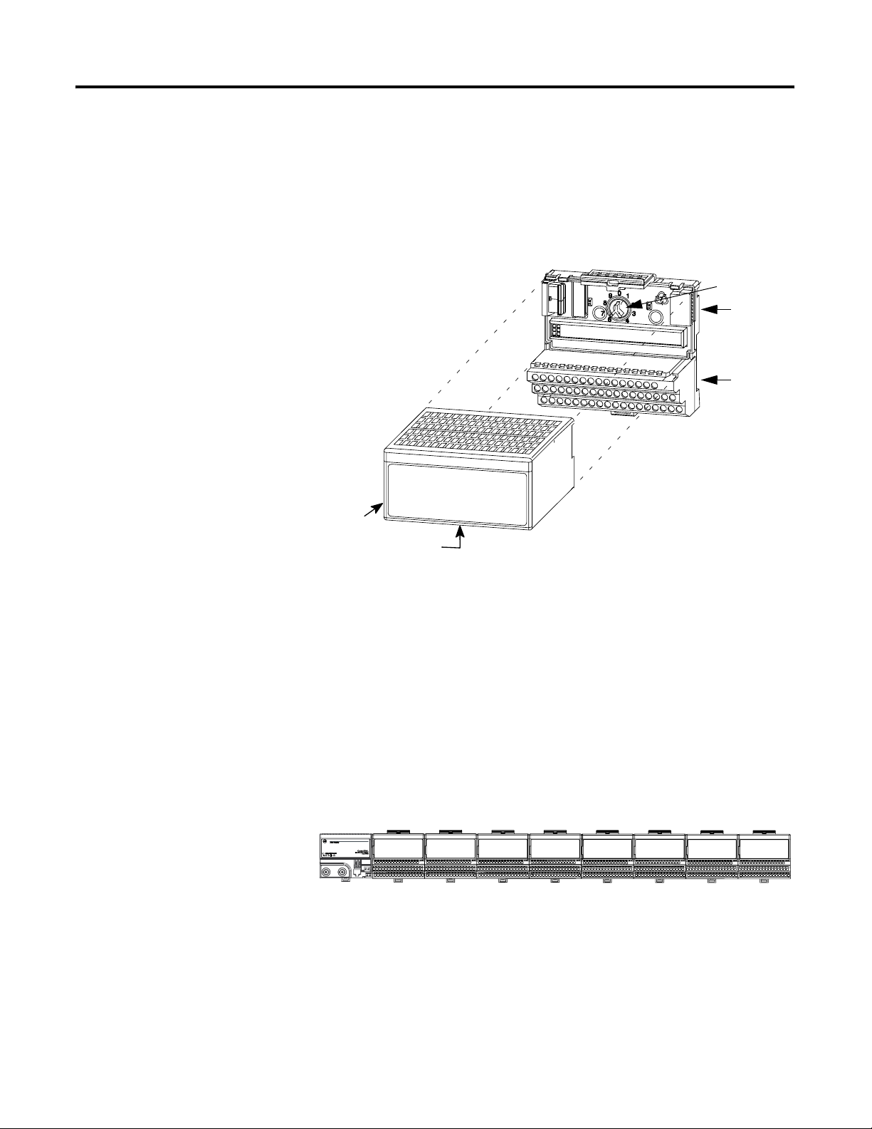
(1) keyswitch
(8) flexbus
cover
(2) terminal
base unit
General Installation
Label here or under here
FLEX Ex I/O modules must be used with a 1797-TB3 or -TB3S intrinsically
safe terminal base unit.
You will need to rotate the keyswitch (1) to the correct position depending on
the module. Refer to the module’s installation instructions for more
information. Do not change the position of the keyswitch after wiring the
terminal base unit.
Make certain that you only connect terminal base units to other intrinsically
safe system modules, adapters or power supplies to maintain the integrity of
the intrinsically-safe backplane.
Remove cap plug and attach another intrinsically safe terminal base unit to the
right of the terminal base unit (2) if required.
40231
41307
Do not remove the flexbus cover (8) on the right-most terminal base unit.
1 Publication 1797-6.5.6 - June 2005
Page 30
1-2 General CENELEC Certification Information
Installation in Zone 1
Installation in Zone 22
Electrostatic Charge
European Community Directive Compliance
Modules, adapters, and terminal base units must not be exposed to the
environment. Provide a suitable enclosure. The modules, adapters, and
terminal base units have a protection factor of IP20.
ATTENTION
When the ControlNet Ex system is installed in Zone 22, all system
components (except the coax cable and ControlNet Ex taps) must be installed
in cabinets of the following type: IVK-ISRPI-V16LC; IVK-ISRPI-V8HYW;
or IVK-ISRPI-V8LC. For more information on these cabinets, see page 1-4.
Protect the system against electrostatic charge. Post a sign near each module:
Attention! Avoid electrostatic charge. For your convenience, a sign which
can be cut out and posted is included in this chapter.
If this product has the CE mark it is approved for installation within the
European Community or EEA regions. It has been designed and tested to
meet the following directives.
Modules, adapters, and terminal base units cannot be used
in an intrinsically safe environment after they have been
exposed to non-intrinsically safe signals.
EMC Directive
All system components are tested to meet the Council Directive 89/336/EEC
Electromagnetic Compatibility (EMC), as amended by 92/31/EC and
93/68/EEC, by applying the following standards as appropriate:
• EN61000-6-4:2001, Electromagnetic Compatibility (EMC) - Part 6-4:
Generic Standards - Emission Standard for Industrial Environments
(Class A)
• EN61000-6-2:2001, Electromagnetic Compatibility (EMC) - Part 6-2:
Generic Standards - Immunity for Industrial Environments
• EN61326:1997 + A1-A2, Electrical Equipment for Measurement,
Control, and Laboratory Use - Industrial EMC Requirements
LVD Directive
All power supplies are tested to meet the Council Directive 73/23/EEC Low
Voltage Directive, as amended by 93/68/EEC (LVD), by applying the
following standards as appropriate:
• EN50178:1997, Electronic Equipment for Use in Power Installations
Publication 1797-6.5.6 - June 2005
Page 31

General CENELEC Certification Information 1-3
ATEX Directive
All system components are tested to meet the Council Directive 94/9/EC
Equipment and Protective Systems Intended for Use in Potentially Explosive
Atmospheres by applying the following standards, as appropriate:
• EN50014:1997 + A1-A2, Electrical Apparatus for Potentially Explosive
Atmospheres
• EN50018:1995, Electrical Apparatus for Potentially Explosive
Atmospheres - Flameproof Enclosure “d”
• EN50019:1996, Electrical Apparatus for Potentially Explosive
Atmospheres - Increased Safety “e”
• EN50020:1994, Electrical Apparatus for Potentially Explosive
Atmospheres - Intrinsic Safety “i”
• EN50021: 1999, Electrical Apparatus for Potentially Explosive
Atmospheres - Type of Protection “n”
• EN50281-1-1:1998 + A1, Electrical Apparatus for Use in the Presence
of Combustible Dust - Part 1-1: Protection by Enclosure
• EN50284:1999, Special requirements for construction, test and marking
of electrical apparatus of equipment group II, category 1G
Repair
The power supply is tested to meet the Council Directive 76/117/EC
Electrical Apparatus for Explosive Atmospheres by applying the following
standards:
• EN50014:1977 + A1-A5, Electrical Apparatus for Potentially Explosive
Atmospheres
• EN50018:1977 + A1-A3, Electrical Apparatus for Potentially Explosive
Atmospheres - Flameproof Enclosure “d”
• EN50019:1977 + A1-A5, Electrical Apparatus for Potentially Explosive
Atmospheres - Increased Safety “e”
• EN50020:1977 + A1-A5, Electrical Apparatus for Potentially Explosive
Atmospheres - Intrinsic Safety “i”
System components are not field-repairable. Any attempt to open a system
component will void the warranty and the IS certification. If repair is
necessary, return the system component to the manufacturer.
Attention: Avoid electrostatic charge.
Publication 1797-6.5.6 - June 2005
Page 32

1-4 General CENELEC Certification Information
About Zone 22 Junction Boxes (Cabinets)
ATTENTION
ATTENTION
Pepperl+Fuchs junction boxes (type IVK2-ISRPI-V8LC,
IVK2-ISRPI-V8HYW, or IVK2-ISPRI-V16LC) ensures the basic protection
for the intrinsically safe apparatus of the FLEX Ex system for use in Zone 22.
It corresponds with category 3D according to RL 94/9 EG and with the type
label marked with the following information:
Pepperl+Fuchs GmbH
68301 Mannheim
IVK2-ISRPI-V8LC (or IVK2-ISRPI-V8HYW or IVK2-ISRPI-V16LC)
EX (Hexagon) II 3D IP54 T 70°C
CE
Serial (manufacturing) number
Model
When installing, commissioning, operating, and
maintaining devices with intrinsically safe circuits, the
certificate of conformity of the devices, as well as the
applicable national and local construction, installation, and
operating regulations must be heeded (in Germany DIN
EN 50020, DIN VDE 0165).
Repairs to devices having intrinsically safe circuitry may
only be carried out by qualified personnel in accordance
with the valid regulations (Elex V).
Publication 1797-6.5.6 - June 2005
The maximum dissipation is limited to 60W for the IVK2-ISRPI-V8LC and
IVK2-ISRPI-V8HYW junction boxes and 120W for the IVK2-ISRPI-V16LC
junction box.
The maximum ambient temperature for the junction boxes complies with the
internal dissipation. It must be guaranteed that the cabinet internal
temperature 70°C is not exceeded (requirement to the installed FLEX Ex
equipment). For example, the IVK2-ISRPI-V8LC junction box has a
maximum ambient temperature of 45°C with maximum mounting.
All cable entries, which are not equipped with a cable, must be provided with a
seal designated for it (IP54). Drillings in the housing, which are not used due
to less assembly, must be closed seal (IP54).
Close the junction box with the provided key after the assembly and mounting.
If the junction box must be opened for maintenance purposes during
operation, exercise care to prevent dust from penetrating inside of the
enclosure.
Page 33

ControlNet Ex System
Chapter
2
Adapter
1797-ACNR15
Field Power
Connection Terminals
PWR
Bus Connectors
Terminal Strips
Terminal Base
Keyswitch
Flexbus Connector
Ex I/O Module
Ex
PWR
20125-M
1 Publication 1797-6.5.6 - June 2005
Page 34

2-2 ControlNet Ex System
ControlNet Ex System Diagram
Node 4 ... 48
RSD-GW-Ex2.CN
1797-ACNR15/* or
1W
Li negl.
Ci negl.
Flexbus
.
Lo=10µH
Uo=5.4V,
Co=65µF,
.
Io=400mA,
Po=2.16W,
.
.
Power Supply Ui=9.5V,
ChB
ChA
Ii=1A,
Ci<120nF,
Li=negligible
>500kHz
-3
Uo=5.4V,
Io=160mA,
F
>500kHz
Uo=5.4V,
-3
Io=160mA,
F
trk trm
CNet Ex
75 Ohm
tap
ControlNet Ex
C.
o
0.95dB/100m 10MHz > 1.86dB/100m
1.16dB/100m 50MHz > 4. 33dB/100m
C) 0.2MHz > 0.93dB/100m 5MHz > 1.39dB/100m
o
coax trunk cable
Flexbus
.
2
.
Node 3
RSD-GW-Ex2.CN
1797-ACNR15/* or
The ControlNet Ex System is an intrinsically safe system according to EN 50039. When installing the
system, the certificate of conformity and the national installation regulations must be heeded. The
components of the ControlNet Ex system and the interconnections are shown on the installation
drawing (A-B Pub. 1797-6.5.6).
For the transmittal between the safe area and the hazardous area only optical glass-fibers are
permitted. The diameter of a single glass-fiber must be >6um. The power density of the transmitter
diode must be <5mW/mm
Protect the system against electrostatic charge. Post a sign near the main components of the system:
Attention! Avoid electrostatic charge.
.
.
1797-RPFM/* or
RSD-FC-Ex2.CN 3km
1797-RPFM/* or
RSD-FC-Ex2.CN 3km
Node 2
Zone 1
1797-RPA/* or
RSD-CFA-Ex.CN
Hazardous Area
.
.
.
.
.
Power Supply Ui=9.5V,
.
>500kHz
Uo=5.4V,
-3
Io=201mA,
F
.
Ch1
fiber
Ch0
fiber
Ii=1A,
Ci<120nF,
Li=negligible
Lo=10µH
Uo=5.4V,
Co=65µF,
Po=2.16W,
Io=400mA,
.
1
.
Ch1
Ch0
Ii=1A,
Ci<120nF,
Li=negligible
Power Supply Ui=9.5V,
>500kHz
-3
ChB
Uo=5.4V,
Io=160mA,
F
ChA
>500kHz
Uo=5.4V,
-3
Io=160mA,
F
fiber
fiber
tap
ControlNet Ex
The ambient temperature range of the ControlNet Ex system is -20 to +70
The Coax Trunk Cable is permitted to have a maximum length of 1,000m with only 2 connected
ControlNet Ex Taps dropping to only 250m with the maximum allowed connected ControlNet Ex
Taps of 48.
coax trunk cable
Cable type 1189A, 3092A, or
3092A Blue from manufacturer
Belden Wire or type RG6-CNet*
tap
ControlNet Ex
tap trm
CNet Ex
Ci < 60pF
ControlNet Ex tap
Li < 560nH
Li < 1100uH Li < 1100uH
Node 1
5.94nF per 100m
0.5MH z >
Cable Capacitance <
Cable Resistance >9.08 Ohm per 100m
Cable Attenuation (-20 to +70
1M Hz > 1.07dB/100m 20MHz > 2.73dB/100m
2M Hz >
*RG6-CNet is defined as: Cable Impedance = 75 Ohm + or - 3 Ohm
Near the main components of the system a plate with the system marking must be attached. If
the system is installed in a cabinet the plate must be fixed on the inside of the cabinet door.
Li negl.
Ci < 68pF
.
RS-FB-Ex2.CN
Safe Area
1797-BCNR or
Publication 1797-6.5.6 - June 2005
.
.
CNet
Zone 0
Hazardous Area
30670-M
Page 35

ControlNet Ex System 2-3
Describing the ControlNet Ex System Diagram
System
Diagram
Name
1797-RPA 1797-RPA ControlNet Ex Modular
1797-RPFM 1797-RPFM ControlNet Ex Fiber
1797-ACNR15 1797-ACNR15 Redundant Media
1797-BCNR 1797-BCNR Redundant ControlNet
CNet Ex
Tap Trm
ControlNet Ex
Tap
CNet Ex
Trk Trm
Coax Trunk
Cable
None None Standard Coax Trunk
A maximum of 48 ControlNet ExTM nodes may be connected together by
250m of coax cable and 48 taps. The distance increases to 1000m when you
use only 2 taps. See the table below for more information.
The fiber media of the 1797-RPFM can be installed in a hazardous location
(Zone 0, 1 or 2) to connect two 1797-RPFM modules or they can be installed
through different locations into the non-hazardous location to connect the
1797-RPFM with any approved associated apparatus.
All cables and fiber media that are not light blue must be marked as IS using
the 1797-EXMK marking kit or other locally approved IS identification
and/or segregation method.
During the installation of the ControlNet Ex system, all metallic parts must be
isolated to prevent an earth connection (high voltage withstanding of isolating
material must be > 500V ac).
Catalog Number Catalog Name Description
Represents one ControlNet Ex node and
Repeater Adapter
Repeater Module,
Medium Distance
ControlNet Ex Adapter
Ex Barrier
1797-TCAP ControlNet Ex Tap
(Dummy) Terminator
1797-TPx ControlNet Ex Coax
Tap
1797-XT ControlNet Ex Trunk
Termin at or
1786-RG6 Quad-Shield, RG-6
75Ω Coax Trunk Cable
Cable BNC Couplers
must be connected to a coax trunk cable
by
1797-TPx
Allows connection of a maximum of two
devices per 1797-RPA and is powered
directly by 1797-RPA
Represents one ControlNet Ex node and
must be connected to a coax trunk cable
by
1797-TPx -each one with two redundant
output channels that are connected to
different ControlNet Ex networks (coax
cables and 1797-TPx)
Allows connection between ControlNet and
ControlNet Ex networks
Represents one ControlNet Ex node and is
a simple capacitor (56pF) with a coax
connector
Four types of connections available: S
(straight t-tap), R (right angle t-tap), YS
(straight y-tap), and YR (right angle y-tap)
- a maximum of 48 taps can be connected
together by coax trunk cable
Simple resistor (75Ω) with coax connector
that must be on each end of the ControlNet
Ex coax trunk for termination
Maximum (functional) length between 2
1797-TPx is 3280ft (1000m) - each
1797-TPx reduces the (functional) coax
cable length by 53.4ft (16.3m)
Different standard cable couplers, 90o,
o
180
, etc.
Publication 1797-6.5.6 - June 2005
Page 36

2-4 ControlNet Ex System
Certified Equivalent ControlNet Ex System Diagram Items
You may use these items as equivalents for the items shown on the system
diagram.
System Diagram Name Catalog Number Source
1797-RPA 1797-RPA Allen-Bradley
RSD-CFA-Ex.CN Pepperl+Fuchs
1797-RPFM 1797-RPFM Allen-Bradley
RSD-FC-Ex2.CN Pepperl+Fuchs
1797-ACNR15 1797-ACNR15 Allen-Bradley
RSD-GW-Ex2.CN Pepperl+Fuchs
1797-BCNR 1797-BCNR Allen-Bradley
RS-FB-Ex2.CN Pepperl+Fuchs
Coax Trunk Cable
1
1786-RG6 Allen-Bradley
2
3092A
Belden Wire & Cable Co.
3092A with blue jacket Belden Wire & Cable Co.
ControlNet Ex Tap 1797-TPx Allen-Bradley
RS-TPx-Ex Pepperl+Fuchs
CNet Ex Trk Trm 1797-XT Allen-Bradley
RS-XT-Ex Pepperl+Fuchs
CNet Ex Tap Trm 1797-TCAP Allen-Bradley
RS-TCAP-Ex Pepperl+Fuchs
1 In addition to these cable types, the following specification can be followed to allow additional types:
Cable Impedance = 75Ω ± 3Ω
Cable Capacitance = <
Cable Resistance = >
Cable Attenuation 0.2MHz >
(-20 to +70
2 Belden Wire & Cable 1189A may be used, but with functional loss of communication distance and/or nodes.
o
C) 0.5MHz > 0.95dB/100m 10MHz > 1.86dB/100m
5.94nF per 100m
9.08Ω per 100m
1MHz >
2MHz >
0.93dB/100m 5MHz > 1.39dB/100m
1.07dB/100m 20MHz > 2.73dB/100m
1.16dB/100m 50MHz > 4.33dB/100m
Publication 1797-6.5.6 - June 2005
Page 37

ControlNet Ex System 2-5
Installation in Zone 1
Modules must not be exposed to the environment. Provide a suitable metal
enclosure. A label with this system marking must be attached near the main
components of the system. If the system is installed in a cabinet, this label
must be fixed inside the cabinet.
Allen-Bradley
1 Allen-Bradley Dr.
Mayfield Hts., OH USA
ControlNet Ex System
DMT 99 ATEX E 065 X
II (1) 2G SYST EEx ia/ib IIB/C T4
-200C <= Ambient Temperature <= +700C
0102
Attention!
Avoid electrostatic charging!
ATTENTION
Modules cannot be used in an intrinsically safe
environment after they have been exposed to
non-intrinsically safe signals.
Installation in Zone 22
Electrostatic Charge
Repair
When the ControlNet Ex system is installed in Zone 22, all system
components (except the coax cable and ControlNet taps) must be installed in
cabinets of the following type: IVK-ISRPI-V16LC; IVK-ISRPI-V8HYW; or
IVK-ISRPI-V8LC. For more information on these cabinets, see page 1-4.
Protect the system against electrostatic charge. Post a sign near each module:
Attention! Avoid electrostatic charge. For your convenience, a sign which
can be cut out and posted is included in this chapter.
Modules are not field-repairable. Any attempt to open a module will void the
warranty and the IS certification. If repair is necessary, return the module to
the manufacturer.
Attention: Avoid electrostatic charge.
Publication 1797-6.5.6 - June 2005
Page 38

2-6 ControlNet Ex System
General Specifications
ATTENTION
When installing, commissioning, operating, and
maintaining devices with intrinsically safe circuits, the
certificate of conformity of the devices, as well as the
applicable national and local construction, installation, and
operating regulations must be heeded (in Germany DIN
EN 50020, DIN VDE 0165).
ATTENTION
Repairs to devices having intrinsically safe circuitry may
only be carried out by qualified personnel in accordance
with the valid regulations (Elex V).
Operational Temperature -20 to 70oC (-4 to 158oF)
Agency Certification II (1) 2G SYST EEx ia/ib IIB/IIC T4
Certificates DMT 99 ATEX E 065 X
Publication 1797-6.5.6 - June 2005
Page 39

(1) keyswitch
1797-TB3 FLEX Ex Terminal Base Unit
Chapter
3
Label here
General Information
Module Installation
(8) flexbus
cover
FLEX Ex I/O modules must be used with a 1797-TB3 or -TB3S intrinsically
safe terminal base unit.
You will need to rotate the keyswitch (1) to the correct position depending on
the module. Refer to the module’s installation instructions for more
information. Do not change the position of the keyswitch after wiring the
terminal base unit.
Make certain that you only connect terminal base units to other intrinsically
safe system modules or adapters to maintain the integrity of the
intrinsically-safe backplane.
0 1 2 3 4 5 6 7 8 9 10 11 12 13 14 15
16 17 18 19 20 21 22 23 24 25 26 2728 29 30 31 32 33
34 35 36 37 38 39 40 41 42 43 45 46 47 48 49 5044 51
42332
41307
Do not remove the flexbus cover (8) on the right-most terminal base unit.
1 Publication 1797-6.5.6 - June 2005
Page 40

3-2 1797-TB3 FLEX Ex Terminal Base Unit
Inputs
Description
Do not apply any non-intrinsically safe signals to the terminal base.
When using as an intrinsically safe electrical apparatus according to EN50020,
the European directives and regulations must be followed.
The terminals in the terminal base unit may be electrically connected to each
other by the insertion of FLEX Ex I/O modules. See the module installation
instructions to determine this.
IMPORTANT
When interconnecting several lines, you must consider the
total accumulated power and check for intrinsic safety
requirements.
The 1797-TB3 terminal base has 36 wiring connections to/from a plug-in
module. The use of each terminal depends on the module mounted in this
base.
The 1797-TB3 terminal base also has connections for cold junction
compensation and terminals designated for shield termination to chassis
ground.
The terminal base is equipped with a factory-installed tab cover for the
backplane bus connection. The tab cover may be removed only when the
terminal base unit is connected to other terminal base units..
Wiring Connections for Terminal Base 1797-TB3
01 32 4 5 6 7 8 9 10 1112131415
A
26 27 28 29 30 31 32 3325242322212019181716
B
44 45 46 47 48 49 50 5143424140393837363534
C
+V -V -V+V
ATTENTION
No connections allowed to terminals 36 and 49
• Make certain that you power the terminal base unit with
an intrinsically safe power supply. Do not exceed the
41252
values listed in the specifications for the terminal base
unit.
• Do not use the unused terminals on the terminal base
unit. Using these terminals as supporting terminals can
result in damage to modules and/or unintended
operation of your system.
Publication 1797-6.5.6 - June 2005
Page 41

1797-TB3 FLEX Ex Terminal Base Unit 3-3
Intrinsically Safe Specifications
For a full list of specifications, refer to the FLEX Ex Terminal Base
Installation Instructions, publication 1797-5.1.
Terminals Assignments
+34, -35, +50, -51, and 96
pin
female I/O connector
i
30-32, 62-64, 94-96
pins
i
i
36, 49
All Other Terminals
Flexbus Connection Intrinsically Safe U
Operational Temperature -20 to 70
Agency Certification II 2G EEx ia IIC T4
Certificates DMT 98 ATEX E012 U
Only for intrinsically safe circuits
U
<10V dc
i
<2.5A
I
i
< 1nF
C
i
Negligible
L
i
Must not be used for any connection
<30V dc
U
i
<100mA
I
i
<1nF
C
i
Negligible
L
i
<10V dc
i
<400mA
I
i
<1nF
C
i
L
Negligible
i
o
C (-4 to 158oF)
Publication 1797-6.5.6 - June 2005
Page 42

3-4 1797-TB3 FLEX Ex Terminal Base Unit
Notes:
Publication 1797-6.5.6 - June 2005
Page 43

(1) keyswitch
Chapter
1797-TB3S FLEX Ex Terminal Base Unit
4
Label here
General Information
Module Installation
(8) flexbus
cover
42333
FLEX Ex I/O modules must be used with a 1797-TB3 or -TB3S intrinsically
safe terminal base unit.
You will need to rotate the keyswitch (1) to the correct position depending on
the module. Refer to the module’s installation instructions for more
information. Do not change the position of the keyswitch after wiring the
terminal base unit.
Make certain that you only connect terminal base units to other intrinsically
safe system modules or adapters to maintain the integrity of the
intrinsically-safe backplane.
41307
Do not remove the flexbus cover (8) on the right-most terminal base unit.
1 Publication 1797-6.5.6 - June 2005
Page 44

4-2 1797-TB3S FLEX Ex Terminal Base Unit
Inputs
Description
Do not apply any non-instrinsically safe signals to the terminal base.
When using as an intrinsically safe electrical apparatus according to EN50020,
the European directives and regulations must be followed.
The terminals in the terminal base unit may be electrically connected to each
other by the insertion of FLEX Ex I/O modules. See the module installation
instructions to determine this.
IMPORTANT
When interconnecting several lines, you must consider the
total accumulated power and check for intrinsic safety
requirements.
The 1797-TB3S terminal base has 36 wiring connections to/from a plug-in
module. The use of each terminal depends on the module mounted in this
base.
The 1797-TB3S terminal base also has connections for cold junction
compensation and terminals designated for shield termination to chassis
ground.
The terminal base is equipped with a factory-installed tab cover for the
backplane bus connection. The tab cover may be removed only when the
terminal base unit is connected to other terminal base units.
Wiring Connections for Terminal Base 1797-TB3S
0 1 2 3 4 5 6 7 8 9 10 11 12 13 14 15
18 19 20 21 22 23 3324 25 26 27 28 29 30 31 3217
16
35 36 37 38 47 48 49 5034
39 40 41 42 43 44 45 46
Label placed at top of wiring area
Row A
Row B
51
Row C
Publication 1797-6.5.6 - June 2005
ATTENTION
+V -V -V+V
No connections allowed to terminals 36 and 49
• Make certain that you power the terminal base unit with
an intrinsically safe power supply. Do not exceed the
values listed in the specifications for the terminal base
unit.
• Do not use the unused terminals on the terminal base
unit. Using these terminals as supporting terminals can
result in damage to modules and/or unintended
operation of your system.
Row A
Row B
Row C
41254
Page 45

1797-TB3S FLEX Ex Terminal Base Unit 4-3
Intrinsically Safe Specifications
For a full list of specifications, refer to the FLEX Ex Spring Clamp Terminal
Base Installation Instructions, publication 1797-5.2.
Terminals Assignments
+34, -35, +50, -51, and 96
pin
female I/O connector
i
30-32, 62-64, 94-96
pins
i
i
36, 49
All Other Terminals
Flexbus Connection Intrinsically Safe U
Operational Temperature -20 to 70
Agency Certification II 2G EEx ia IIC T4
Certificates DMT 98 ATEX E012 U
Only for intrinsically safe circuits
U
<10V dc
i
<2.5A
I
i
< 1nF
C
i
Negligible
L
i
Must not be used for any connection
<30V dc
U
i
<100mA
I
i
<1nF
C
i
Negligible
L
i
<10V dc
i
<400mA
I
i
<1nF
C
i
L
Negligible
i
o
C (-4 to 158oF)
Publication 1797-6.5.6 - June 2005
Page 46

4-4 1797-TB3S FLEX Ex Terminal Base Unit
Notes:
Publication 1797-6.5.6 - June 2005
Page 47

Chapter
5
1797-IBN16 FLEX Ex 16 NAMUR Input Module
General Information
Module Installation
Inputs
Modules must be used with a 1797-TB3 or -TB3S intrinsically safe terminal
base unit.
Rotate keyswitch on terminal base unit clockwise to position 6 as required for
this type of module. Do not change the position of the keyswitch after
wiring the terminal base unit.
Each input can be operated from a NAMUR sensor or a mechanical contact (if
mechanical inputs are used). Do not apply any non-intrinsically safe
signals to this module.
When using an intrinsically safe electrical apparatus according to EN50020,
the European directives and regulations must be followed.
The channels in this module are electrically connected to each other and have a
common plus-line.
IMPORTANT
When interconnecting several lines, you must consider the
total accumulated power and check for intrinsic safety.
1 Publication 1797-6.5.6 - June 2005
Page 48

5-2 1797-IBN16 FLEX Ex 16 NAMUR Input Module
Wiring to a 1797-TB3 or
-TB3S Terminal Base Unit
0 1 2 3 4 5 6 7 8 9 10 11 12 13 14 15
Row A
+-
Ch 0
16 17 18 19 20 21 22 23 24 2 5 26 27 28 2 9 30 31 32 33
Row B
+-
Ch 8
34 35 36 37 38 39 4 0 41 42 43 44 45 46 47 48 49 50 51
Row C
+V -V +V -V
Connect wiring to the terminal base as shown below.
+-
Ch 1
+-
Ch 9
ATTENTION
+-
Ch 2
+-
Ch 10
+-
Ch 3
+-
Ch 11
No connection allowed to terminals 36 and 49
+-
Ch 4
+-
Ch 12
+-
Ch 5
+-
Ch 13
Do not use any unused terminals on this terminal base unit.
+-
Ch 6
+-
Ch 14
Using these terminals as supporting terminals can result in
damage to the module and/or unintended operation of
your system.
+-
Ch 7
+-
Ch 15
41504
Intrinsically Safe Specifications
For a full list of specifications, refer to FLEX Ex 16 NAMUR Input Module
Installation Instructions, publication 1797-5.7.
Output (intrinsically safe)
(16 position male/female flexbus
connector)
Power Supply
(+V, -V Intrinsically Safe)
Operating Temperature -20 to +70
Agency Certification II (1) 2G EEx ia/ib IIB/IIC T4
Certificates DMT 98 ATEX E 013 X
Ui < 5.8V
< 400mA
I
i
Li = Negligible
Ci = Negligible
< 9.5V dc
U
i
< 1A
I
i
= Negligible
L
i
= Negligible
C
i
o
C (-4 to +158oF)
II (1D) (2D)
Publication 1797-6.5.6 - June 2005
Page 49

CE/CENELEC I/O Entity Parameters (Each Channel)
U
< 14.5V
o
< 15mA
I
o
< 40mW
P
o
Characteristic:
linear
1797-IBN16 FLEX Ex 16 NAMUR Input Module 5-3
Protection Group Allowed
Capacitance
EEx ia IIB 1µF 10mH 2.6mH/Ω
EEx ia IIC 300nF 2mH 0.65mH/Ω
Allowed
Inductance
Lo/Ro Ratio
Publication 1797-6.5.6 - June 2005
Page 50

5-4 1797-IBN16 FLEX Ex 16 NAMUR Input Module
Notes:
Publication 1797-6.5.6 - June 2005
Page 51

Chapter
6
1797-OB4D FLEX Ex 24V dc Non-Isolated Source 4 Output Module
General Information
Module Installation
Outputs
Wiring to a 1797-TB3 or
-TB3S Terminal Base Unit
Modules must be used with a 1797-TB3 or -TB3S intrinsically safe terminal
base unit.
Rotate keyswitch on terminal base unit clockwise to position 7 as required for
this type of module. Do not change the position of the keyswitch after
wiring the terminal base unit.
Each output can operate a discrete field device. Do not apply any
non-intrinsically safe signals to this module.
When using an intrinsically safe electrical apparatus according to EN50020,
the European directives and regulations must be followed.
The channels in this module are electrically connected to each other.
Connect wiring to the terminal base as shown below.
0 1 2 3 4 5 6 7 8 9 10 11 12 13 14 15
Row A
++++----
ch0 ch1 ch2 ch3
16 17 18 19 20 21 22 23 24 2 5 26 27 28 2 9 30 31 32 33
Row B
34 35 36 37 38 39 4 0 41 42 43 44 45 46 47 48 49 50 51
Row C
+V +V-V -V
1 Publication 1797-6.5.6 - June 2005
No connections allowed to terminals 2, 3, 6, 7, 10, 11, 14, 15, 17 to 32, 36, 37,
38, 39, 46, 47, 48, 49
40068
Page 52

6-2 1797-OB4D FLEX Ex 24V dc Non-Isolated Source 4 Output Module
Intrinsically Safe Specifications
ATTENTION
Do not use any unused terminals on this terminal base unit.
Using these terminals as supporting terminals can result in
damage to the module and/or unintended operation of
your system.
For a full list of specifications, refer to FLEX Ex 24V dc Non-Isolated Source
4 Output Module Installation Instructions, publication 1797-5.6.
Output (intrinsically safe)
(16 position male/female flexbus
connector)
Power Supply
(+V, -V Intrinsically Safe)
Operating Temperature -20 to +70
Agency Certification II (1) 2G EEx ia/ib IIB/IIC T4
Certificates DMT 98 ATEX E 040 X
Ui < 5.8V
< 400mA
I
i
Li = Negligible
Ci = 1.35
U
< 1A
I
i
L
C
II (1D) (2D)
µF
< 9.5V dc
i
= Negligible
i
< Negligible
i
o
C (-4 to +158oF)
CE/CENELEC I/O Entity Parameters
Publication 1797-6.5.6 - June 2005
Signal output (+ to -) for ch 0 to ch 3 (terminals: 0-1; 4-5; 8-9; 12-13)
1797-OB4D
U
= 27.4V
o
= 110mA
I
o
If
concentrated
capacitance
and/or
inductance
are available,
use the
following
values.
Protection Group Allowed
Capacitance
EEx ia IIB 677nF 8mH
IIC 87nF 2mH
EEx ia IIB 150nF 5mH
IIC 30nF 2mH
Allowed
Inductance
Page 53

Chapter
1797-IE8 FLEX Ex 8 Input Analog Module
7
General Information
Module Installation
Inputs
Modules must be used with a 1797-TB3 or -TB3S intrinsically safe terminal
base unit.
Rotate keyswitch on terminal base unit clockwise to position 3 as required for
this type of module. Do not change the position of the keyswitch after
wiring the terminal base unit.
Each input can be operated from an analog field device signal. Do not apply
any non-intrinsically safe signals to this module.
When using an intrinsically safe electrical apparatus according to EN50020,
the European directives and regulations must be followed.
The channels in this module are electrically connected to each other and have a
common plus-line.
IMPORTANT
When interconnecting several lines, you must consider the
total accumulated power and check for intrinsic safety.
1 Publication 1797-6.5.6 - June 2005
Page 54

7-2 1797-IE8 FLEX Ex 8 Input Analog Module
Wiring to a 1797-TB3 or
-TB3S Terminal Base Unit
0 1 2 3 4 5 6 7 8 9 10 11 12 13 14 15
Row A
16 17 18 19 20 21 22 23 24 2 5 26 27 28 2 9 30 31 32 33
Row B
34 35 36 37 38 39 40 41 42 43 44 45 46 47 48 49 50 51
Row C
+V -V +V -V
Connect wiring to the terminal base as shown below.
+-+-+-+-
sigsigsigsig
No connection
allowed
ATTENTION
Ch 2Ch 1Ch 0
Do not use any unused terminals on this terminal base unit.
Ch 3
+-+-+-+-
sigsigsigsig
Ch 7Ch 6Ch 5Ch 4
Ch 7
Using these terminals as supporting terminals can result in
damage to the module and/or unintended operation of
your system.
40071
No connection
allowed
Intrinsically Safe Specifications
For a full list of specifications, refer to FLEX Ex 8 Input Analog Module
Installation Instructions, publication 1797-5.5.
Output (intrinsically safe)
(16 position male/female flexbus
connector)
Power Supply
(+V, -V Intrinsically Safe)
Operating Temperature
Agency Certification II (1) 2G EEx ia/ib IIB/IIC T4
Certificates DMT 98 ATEX E 020 X
Ui < 5.8V
< 400mA
I
i
L
= Negligible
i
< 1.35µF
C
i
< 9.5V dc
U
i
< 1A
I
i
= Negligible
L
i
= Negligible
C
i
-20 to +70
II (1D) (2D)
o
C (-4 to +158oF)
Publication 1797-6.5.6 - June 2005
Page 55

1797-IE8 FLEX Ex 8 Input Analog Module 7-3
CE/CENELEC I/O Entity Parameters
Measurement input (sig to -) for ch 0 to ch 7 (terminals: 1-2; 5-6; 9-10; 13-14;
18-19; 22-23; 26-27; 30-31)
U
= 5V
o
= 1mA
I
o
= 1.3mW
P
o
= 28V
U
i
= 93mA
I
i
C
and Li
i
negligible
Protection Group Allowed
Capacitance
EEx ia IIB 1000µF 1H
IIC 100µF 1H
Allowed
Inductance
Source output (+ to sig) for ch 0 to ch 7 (terminals: 0-1; 4-5; 8-9; 12-13; 17-18;
21-22; 25-26; 29-30)
= 23.7V
U
o
= 92.5mA
I
o
= 548mW
P
o
If concentrated
capacitance
and/or
inductance are
available, use the
following values.
Protection Group Allowed
Capacitance
EEx ia IIB 560nF 10mH
IIC 66nF 2.5mH
EEx ia IIB 320nF 10mH
IIC 60nF 2mH
Allowed
Inductance
Source output plus measurement input (+ to -) for ch 0 to ch 7 (terminals: 0-2;
4-6; 8-10; 12-14; 17-19; 21-23; 25-27; 29-31)
U
= 23.7V
o
= 93.5mA
I
o
= 555mW
P
o
If concentrated
capacitance
and/or
inductance are
available, use the
following values.
Protection Group Allowed
Capacitance
EEx ia IIB 560nF 10mH
IIC 66nF 2.5mH
EEx ia IIB 320nF 10mH
IIC 60nF 2mH
Allowed
Inductance
Publication 1797-6.5.6 - June 2005
Page 56

7-4 1797-IE8 FLEX Ex 8 Input Analog Module
Notes:
Publication 1797-6.5.6 - June 2005
Page 57

1797-IE8H FLEX Ex 8 Input HART Analog Module
Chapter
8
General Information
Module Installation
Inputs
Modules must be used with a 1797-TB3 or -TB3S intrinsically safe terminal
base unit.
Rotate keyswitch on terminal base unit clockwise to position 3 as required for
this type of module. Do not change the position of the keyswitch after
wiring the terminal base unit.
Each input can be operated from an analog field device signal. Do not apply
any non-intrinsically safe signals to this module.
When using an intrinsically safe electrical apparatus according to EN50020,
the European directives and regulations must be followed.
The channels in this module are electrically connected to each other and have a
common plus-line.
IMPORTANT
When interconnecting several lines, you must consider the
total accumulated power and check for intrinsic safety.
1 Publication 1797-6.5.6 - June 2005
Page 58

8-2 1797-IE8H FLEX Ex 8 Input HART Analog Module
Wiring to a 1797-TB3 or
-TB3S Terminal Base Unit
0 1 2 3 4 5 6 7 8 9 10 11 12 13 14 15
Row A
16 17 18 19 20 21 22 23 24 2 5 26 27 28 2 9 30 31 32 33
Row B
34 35 36 37 38 39 40 41 42 43 44 45 46 47 48 49 50 51
Row C
+V -V +V -V
Connect wiring to the terminal base as shown below.
+-+-+-+-
sigsigsigsig
No connection
allowed
ATTENTION
Ch 2Ch 1Ch 0
Do not use any unused terminals on this terminal base unit.
Ch 3
+-+-+-+-
sigsigsigsig
Ch 7Ch 6Ch 5Ch 4
Ch 7
Using these terminals as supporting terminals can result in
damage to the module and/or unintended operation of
your system.
40071
No connection
allowed
Intrinsically Safe Specifications
For a full list of specifications, refer to FLEX Ex Analog Input Modules
Installation Instructions, publication 1797-5.5.
Output (intrinsically safe)
(16 position male/female flexbus
connector)
Power Supply
(+V, -V Intrinsically Safe)
Operating Temperature
Agency Certification II (1) 2G EEx ia/ib IIB/IIC T4
Certificates DMT 98 ATEX E 020 X
Ui < 5.8V
< 400mA
I
i
L
= Negligible
i
< 1.35µF
C
i
< 9.5V dc
U
i
< 1A
I
i
= Negligible
L
i
= Negligible
C
i
-20 to +70
II (1D) (2D)
o
C (-4 to +158oF)
Publication 1797-6.5.6 - June 2005
Page 59

1797-IE8H FLEX Ex 8 Input HART Analog Module 8-3
CE/CENELEC I/O Entity Parameters
Measurement input (sig to -) for ch 0 to ch 7 (terminals: 1-2; 5-6; 9-10; 13-14;
18-19; 22-23; 26-27; 30-31)
U
= 5V
o
= 1mA
I
o
= 1.3mW
P
o
= 28V
U
i
= 93mA
I
i
C
and Li
i
negligible
Protection Group Allowed
Capacitance
EEx ia IIB 1000µF 1H
IIC 100µF 1H
Allowed
Inductance
Source output (+ to sig) for ch 0 to ch 7 (terminals: 0-1; 4-5; 8-9; 12-13; 17-18;
21-22; 25-26; 29-30)
= 23.7V
U
o
= 92.5mA
I
o
= 548mW
P
o
If concentrated
capacitance
and/or
inductance are
available, use the
following values.
Protection Group Allowed
Capacitance
EEx ia IIB 560nF 10mH
IIC 66nF 2.5mH
EEx ia IIB 320nF 10mH
IIC 60nF 2mH
Allowed
Inductance
Source output plus measurement input (+ to -) for ch 0 to ch 7 (terminals: 0-2;
4-6; 8-10; 12-14; 17-19; 21-23; 25-27; 29-31)
U
= 23.7V
o
= 93.5mA
I
o
= 555mW
P
o
If concentrated
capacitance
and/or
inductance are
available, use the
following values.
Protection Group Allowed
Capacitance
EEx ia IIB 560nF 10mH
IIC 66nF 2.5mH
EEx ia IIB 320nF 10mH
IIC 60nF 2mH
Allowed
Inductance
Publication 1797-6.5.6 - June 2005
Page 60

8-4 1797-IE8H FLEX Ex 8 Input HART Analog Module
Notes:
Publication 1797-6.5.6 - June 2005
Page 61

Chapter
1797-IE8NF FLEX Ex 8 Input Analog Module with Noise Filter
9
General Information
Module Installation
Inputs
Modules must be used with a 1797-TB3 or -TB3S intrinsically safe terminal
base unit.
Rotate keyswitch on terminal base unit clockwise to position 3 as required for
this type of module. Do not change the position of the keyswitch after
wiring the terminal base unit.
Each input can be operated from an analog field device signal. Do not apply
any non-intrinsically safe signals to this module.
When using an intrinsically safe electrical apparatus according to EN50020,
the European directives and regulations must be followed.
The channels in this module are electrically connected to each other and have a
common plus-line.
IMPORTANT
When interconnecting several lines, you must consider the
total accumulated power and check for intrinsic safety.
1 Publication 1797-6.5.6 - June 2005
Page 62

9-2 1797-IE8NF FLEX Ex 8 Input Analog Module with Noise Filter
Wiring to a 1797-TB3 or
-TB3S Terminal Base Unit
0 1 2 3 4 5 6 7 8 9 10 11 12 13 14 15
Row A
16 17 18 19 20 21 22 23 24 2 5 26 27 28 2 9 30 31 32 33
Row B
34 35 36 37 38 39 40 41 42 43 44 45 46 47 48 49 50 51
Row C
+V -V +V -V
Connect wiring to the terminal base as shown below.
+-+-+-+-
sigsigsigsig
No connection
allowed
ATTENTION
Ch 2Ch 1Ch 0
Do not use any unused terminals on this terminal base unit.
Ch 3
+-+-+-+-
sigsigsigsig
Ch 7Ch 6Ch 5Ch 4
Ch 7
Using these terminals as supporting terminals can result in
damage to the module and/or unintended operation of
your system.
40071
No connection
allowed
Intrinsically Safe Specifications
For a full list of specifications, refer to FLEX Ex Analog Input Modules
Installation Instructions, publication 1797-5.5.
Output (intrinsically safe)
(16 position male/female flexbus
connector)
Power Supply
(+V, -V Intrinsically Safe)
Operating Temperature
Agency Certification II (1) 2G EEx ia/ib IIB/IIC T4
Certificates DMT 98 ATEX E 020 X
Ui < 5.8V
< 400mA
I
i
L
= Negligible
i
< 1.35µF
C
i
< 9.5V dc
U
i
< 1A
I
i
= Negligible
L
i
= Negligible
C
i
-20 to +70
II (1D) (2D)
o
C (-4 to +158oF)
Publication 1797-6.5.6 - June 2005
Page 63

1797-IE8NF FLEX Ex 8 Input Analog Module with Noise Filter 9-3
CE/CENELEC I/O Entity Parameters
Measurement input (sig to -) for ch 0 to ch 7 (terminals: 1-2; 5-6; 9-10; 13-14;
18-19; 22-23; 26-27; 30-31)
U
= 5V
o
= 1mA
I
o
= 1.3mW
P
o
= 28V
U
i
= 93mA
I
i
C
and Li
i
negligible
Protection Group Allowed
Capacitance
EEx ia IIB 1000µF 1H
IIC 100µF 1H
Allowed
Inductance
Source output (+ to sig) for ch 0 to ch 7 (terminals: 0-1; 4-5; 8-9; 12-13; 17-18;
21-22; 25-26; 29-30)
= 23.7V
U
o
= 92.5mA
I
o
= 548mW
P
o
If concentrated
capacitance
and/or
inductance are
available, use the
following values.
Protection Group Allowed
Capacitance
EEx ia IIB 560nF 10mH
IIC 66nF 2.5mH
EEx ia IIB 320nF 10mH
IIC 60nF 2mH
Allowed
Inductance
Source output plus measurement input (+ to -) for ch 0 to ch 7 (terminals: 0-2;
4-6; 8-10; 12-14; 17-19; 21-23; 25-27; 29-31)
U
= 23.7V
o
= 93.5mA
I
o
= 555mW
P
o
If concentrated
capacitance
and/or
inductance are
available, use the
following values.
Protection Group Allowed
Capacitance
EEx ia IIB 560nF 10mH
IIC 66nF 2.5mH
EEx ia IIB 320nF 10mH
IIC 60nF 2mH
Allowed
Inductance
Publication 1797-6.5.6 - June 2005
Page 64

9-4 1797-IE8NF FLEX Ex 8 Input Analog Module with Noise Filter
Notes:
Publication 1797-6.5.6 - June 2005
Page 65

Chapter
10
1797-OE8 FLEX Ex 8 Output Analog Module
General Information
Module Installation
Outputs
Wiring to a 1797-TB3 or
-TB3S Terminal Base Unit
Modules must be used with a 1797-TB3 or -TB3S intrinsically safe terminal
base unit.
Rotate keyswitch on terminal base unit clockwise to position 4 as required for
this type of module. Do not change the position of the keyswitch after
wiring the terminal base unit.
Each output channel can operate an analog field device. Do not apply any
non-intrinsically safe signals to this module.
When using an intrinsically safe electrical apparatus according to EN50020,
the European Community directives and regulations must be followed.
The channels in this module are electrically connected to each other.
Connect wiring to the terminal base as shown below.
0 1 2 3 4 5 6 7 8 9 10 11 12 13 14 15
Row A
+- + - + - + -
ch0
16 17 18 19 20 21 22 23 24 2 5 26 27 28 2 9 30 31 32 33
Row B
++++----
ch4 ch5 ch6
34 35 36 37 38 39 40 41 42 43 44 45 46 47 48 49 50 51
Row C
+V +V-V -V
1 Publication 1797-6.5.6 - June 2005
ch1 ch2 ch3
ch7
No connections allowed to terminals 2, 3, 6, 7, 10, 11, 14, 15, 19, 20, 23,
24, 27, 28, 31, 32, 36, 37, 38, 39, 46, 47, 48, 49
41440
Page 66

10-2 1797-OE8 FLEX Ex 8 Output Analog Module
General Specifications
ATTENTION
Do not use any unused terminals on this terminal base unit.
Using these terminals as supporting terminals can result in
damage to the module and/or unintended operation of
your system.
For a full list of specifications, refer to FLEX Ex 8 Analog Output Modules
Installation Instructions, publication 1797-5.3.
Output (Intrinsically Safe)
(16 pin male and female
flexbus connector)
Power Supply
(+V, -V Intrinsically Safe)
Operational Temperature
Agency Certification II (1) 2G EEx ia/ib IIB/IIC T4
Certificates DMT 00 ATEX E 042 X
Ui < 5.8V dc
< 400mA
I
i
L
= Negligible
i
< 1.35µF
C
i
< 9.5V dc
U
i
< 1A
I
i
= Negligible
L
i
= Negligible
C
i
-20 to +70
II (1D) (2D)
o
C (-4 to +158oF)
CE, CENELEC I/O Entity Parameters
Publication 1797-6.5.6 - June 2005
Signal output (+ to -) for ch 0 to ch 7 (terminals: 0-1; 4-5; 8-9; 12-13; 17-18;
21-22; 25-26; 29-30)
U
= 21V
o
= 100mA
I
o
P
= 520mW
o
If concentrated
capacitance
and/or
inductance are
available, use the
following values.
Protection Group Allowed
Capacitance
EEx ia IIB 1.27µF8mH
IIC 188nF 2mH
EEx ia IIB 295nF 10mH
IIC 70nF 2mH
Allowed
Inductance
Page 67

Chapter
1797-OE8H FLEX Ex 8 Output HART Analog Module
11
General Information
Module Installation
Outputs
Wiring to a 1797-TB3 or
-TB3S Terminal Base Unit
Modules must be used with a 1797-TB3 or -TB3S intrinsically safe terminal
base unit.
Rotate keyswitch on terminal base unit clockwise to position 4 as required for
this type of module. Do not change the position of the keyswitch after
wiring the terminal base unit.
Each output channel can operate an analog field device. Do not apply any
non-intrinsically safe signals to this module.
When using an intrinsically safe electrical apparatus according to EN50020,
the European Community directives and regulations must be followed.
The channels in this module are electrically connected to each other.
Connect wiring to the terminal base as shown below.
0 1 2 3 4 5 6 7 8 9 10 11 12 13 14 15
Row A
+- + - + - + -
ch0
16 17 18 19 20 21 22 23 24 2 5 26 27 28 2 9 30 31 32 33
Row B
++++----
ch4 ch5 ch6
34 35 36 37 38 39 40 41 42 43 44 45 46 47 48 49 50 51
Row C
+V +V-V -V
1 Publication 1797-6.5.6 - June 2005
ch1 ch2 ch3
ch7
No connections allowed to terminals 2, 3, 6, 7, 10, 11, 14, 15, 19, 20, 23,
24, 27, 28, 31, 32, 36, 37, 38, 39, 46, 47, 48, 49
41440
Page 68

11-2 1797-OE8H FLEX Ex 8 Output HART Analog Module
General Specifications
ATTENTION
Do not use any unused terminals on this terminal base unit.
Using these terminals as supporting terminals can result in
damage to the module and/or unintended operation of
your system.
For a full list of specifications, refer to FLEX Ex 8 Analog Output Modules
Installation Instructions, publication 1797-5.3.
Output (Intrinsically Safe)
(16 pin male and female
flexbus connector)
Power Supply
(+V, -V Intrinsically Safe)
Operational Temperature
Agency Certification II (1) 2G EEx ia/ib IIB/IIC T4
Certificates DMT 00 ATEX E 042 X
Ui < 5.8V dc
< 400mA
I
i
L
= Negligible
i
< 1.35µF
C
i
< 9.5V dc
U
i
< 1A
I
i
= Negligible
L
i
= Negligible
C
i
-20 to +70
II (1D) (2D)
o
C (-4 to +158oF)
CE, CENELEC I/O Entity Parameters
Publication 1797-6.5.6 - June 2005
Signal output (+ to -) for ch 0 to ch 7 (terminals: 0-1; 4-5; 8-9; 12-13; 17-18;
21-22; 25-26; 29-30)
U
= 21V
o
= 100mA
I
o
P
= 520mW
o
If concentrated
capacitance
and/or
inductance are
available, use the
following values.
Protection Group Allowed
Capacitance
EEx ia IIB 1.27µF8mH
IIC 188nF 2mH
EEx ia IIB 295nF 10mH
IIC 70nF 2mH
Allowed
Inductance
Page 69

Chapter
1797-IRT8 FLEX Ex Thermocouple/RTD Input Module
12
General Information
Module Installation
Inputs
Modules must be used with a 1797-TB3 or -TB3S intrinsically safe terminal
base unit.
Rotate keyswitch on terminal base unit clockwise to position 2 as required for
this type of module. Do not change the position of the keyswitch after
wiring the terminal base unit.
Each input can be operated from a thermocouple (TC) or resistance
temperature detector (RTD). Do not apply any non-intrinsically safe
signals to this module.
When using an intrinsically safe electrical apparatus according to EN50020,
the European directives and regulations must be followed.
The channels in this module are electrically connected to each other and have a
common plus-line.
IMPORTANT
When interconnecting several lines, you must consider the
total accumulated power and check for intrinsic safety.
1 Publication 1797-6.5.6 - June 2005
Page 70

12-2 1797-IRT8 FLEX Ex Thermocouple/RTD Input Module
Wiring to a 1797-TB3 or
-TB3S Terminal Base Unit
Row A
Row B
Row C
Connect wiring to the terminal base as shown below.
0 1 2 3 4 5 6 7 8 9 10 11 12 13 14 15
+L
H-+ LH-+ LH-+LH-
16 17 18 19 20 21 22 23 24 25 26 27 28 29 30 31 32 33
+LH-+ LH-+ LH-+LH-
34 35 36 37 38 39 4 0 41 4 2 43 44 45 46 47 48 49 50 51
+V CJC -V
-V CJC
ATTENTION
0+ 0- 1-1+
chassis
GND for
shield
No connection allowed to terminals 36 and 49
Do not use any unused terminals on this terminal base unit.
Ch 2Ch 1Ch 0 Ch 3
Ch 7Ch 6Ch 5Ch 4
Ch 7
chassis
GND for
shield
Using these terminals as supporting terminals can result in
damage to the module and/or unintended operation of
your system.
+V
41505
Intrinsically Safe Specifications
For a full list of specifications, refer to FLEX Ex Thermocouple/RTD Input
Module Installation Instructions, publication 1797-5.4.
Output (intrinsically safe)
(16 position male/female flexbus
connector)
Power Supply
(+V, -V Intrinsically Safe)
Operational Temperature -20 to +70
Agency Certification II (1) 2G EEx ia/ib IIB/IIC T4
Certificates DMT 98 ATEX E 023X
Ui < 5.8V
< 400mA
I
i
Li = Negligible
1.35µF
Ci <
U
< 9.5V dc
i
< 1A
I
i
= Negligible
L
i
= Negligible
C
i
o
C (-4 to 158oF)
II (1D) (2D)
Publication 1797-6.5.6 - June 2005
Page 71

1797-IRT8 FLEX Ex Thermocouple/RTD Input Module 12-3
CE/CENELEC I/O Entity Parameters
Input circuits (+ to -) for ch0 to ch7 (terminals: 0-3; 4-7; 8-11; 12-15; 17-20;
21-24; 25-28; 29-32)
U
= 9V
o
= 37mA
I
o
= 83mW
P
o
Protection Group Allowed
Capacitance
EEx ia IIB 40µF 80mH 1.7mH/Ω
EEx ia IIC 4.9µF 20mH 0.4mH/Ω
Allowed
Inductance
Lo/Ro Ratio
CJC circuits (+ to -) for CJC0 and CJC1 (terminals: 37, 39; 46, 48)
U
= 9V
o
= 1mA
I
o
P
= 3mW
o
Protection Group Allowed
Capacitance
EEx ia IIB 40µF 1H 63mH/Ω
EEx ia IIC 4.9µF 1H 15mH/Ω
Allowed
Inductance
L
o/Ro
Ratio
Input circuits (+ to -) for ch0 to ch7 and CJC circuits (+ to -) for CJC0 and
CJC1 (terminals 0-3, 37, 39; 4-7, 37, 39; 8-11, 37, 39; 12-15, 37, 39; 17-20, 37,
39; 21-24, 37, 39; 25-28, 37, 39; 29-32, 37, 39; 0-3, 46, 48; 4-7, 46, 48; 8-11, 46,
48; 12-15, 46, 48; 17-20, 46, 48; 21-14, 46, 48; 25-28, 46, 48; 29-32, 46, 48)
U
= 9V
o
= 38mA
I
o
= 86mW
P
o
Protection Group Allowed
Capacitance
Allowed
Inductance
L
o/Ro
Ratio
EEx ia IIB 40µF 80mH 1.7mH/Ω
EEx ia IIC 4.9µF 20mH 0.4mH/Ω
Publication 1797-6.5.6 - June 2005
Page 72

12-4 1797-IRT8 FLEX Ex Thermocouple/RTD Input Module
Notes:
Publication 1797-6.5.6 - June 2005
Page 73

Chapter
13
1797-IJ2 FLEX Ex Frequency Input Module
General Information
Module Installation
Inputs
Modules must be used with a 1797-TB3 or -TB3S intrinsically safe terminal
base unit.
Rotate keyswitch on terminal base unit clockwise to position 1 as required for
this type of module. Do not change the position of the keyswitch after
wiring the terminal base unit.
The frequency input module has 2 input channels. Each input can accept
inputs from magnetic pickups or proximity probes. Each input channel has 2
input selections: frequency input or gate input. Do not apply any
non-intrinsically safe signals to this module.
The channels in this module are electrically connected to each other.
When using an intrinsically safe electrical apparatus according to EN50020,
the European directives and regulations must be followed.
IMPORTANT
When interconnecting several lines, you must consider the
total accumulated power and check for intrinsic safety.
1 Publication 1797-6.5.6 - June 2005
Page 74

13-2 1797-IJ2 FLEX Ex Frequency Input Module
Wiring to a 1797-TB3 or
-TB3S Terminal Base Unit
Row A
Row B
Row C
Connect wiring to the terminal base as shown below.
0 1 2 3 4 5 6 7 8 9 10 11 12 13 14 15
3V V+
6V GND 50
16 17 18 19 20 21 22 23 24 2 5 26 27 28 2 9 30 31 32 33
R0 NO R0 NC
+V -V
ATTENTION
Channel 0 Frequency Input Channel 1 Frequency Input
34 35 36 37 38 39 4 0 41 42 43 44 45 46 47 48 49 50 51
-V
mV
Sel
GND 50
mV
Sel
Channel 0 Gate Input Channel 1 Gate Input
No connection allowed to terminals 19, 30, 36, 38, 39, 47, 48, 49
Do not use any unused terminals on this terminal base unit.
N500/50 mV8V 8V N GND 6VV+ 3V
N500/50 mV8V 8V N 50
50
500/50
mV
500/50 mVGND R1 NOR1 NC
mV
Sel
mV
Sel
GND
Using these terminals as supporting terminals can result in
damage to the module and/or unintended operation of
your system.
+VR0 COM R1 COM
42334
Intrinsically Safe Specifications
For a full list of specifications, refer to FLEX Ex Frequency Input Module
Installation Instructions, publication 1797-5.7.
Output (intrinsically safe)
(16 position male/female flexbus
connector)
Power Supply
(+V, -V Intrinsically Safe)
Operating Temperature -20 to +70
Agency Certification II (1) 2G EEx ia/ib IIB/IIC T4
Certificates DMT 98 ATEX E 033 X
Uo < 5.8V
< 400mA
I
o
Li = Negligible
2.64µF
Ci <
U
< 9.5V dc
i
< 1A
I
i
= Negligible
L
i
= Negligible
C
i
o
C (-4 to +158oF)
II (1D) (2D)
Publication 1797-6.5.6 - June 2005
Page 75

1797-IJ2 FLEX Ex Frequency Input Module 13-3
CE/CENELEC Input I/O Entity Parameters
Channel 0 Frequency Input
Field devices may only be connected to the terminals of one of the five
following circuits. The terminals of the remaining four circuits must not be
connected.
Namur/Con
tact
(terminals
6-7)
= 14.7V
U
o
I
= 15mA
o
P
= 30mW
o
Magnetic
500mV
(terminals
5-3)
= 14.7V
U
o
I
= 10mA
o
P
= 18mW
o
Protection Group Allowed
Capacitance
EEx ia IIB 3.86µF 300mH 2.6mH/Ω
IIC 620nF 80mH 0.65mH/Ω
Protection Group Allowed
Capacitance
EEx ia IIB 3.86µF 600mH 4.15mH/Ω
IIC 620nF 150mH 1.03mH/Ω
Allowed
Inductance
Allowed
Inductance
L
oRo
Ratio
L
oRo
Ratio
Magnetic
50mV
(terminals
5-3, 6-4)
U
= 14.7V
o
I
= 10mA
o
P
= 18mW
o
Vortex 6V
(terminals
1, 2-3)
U
= 26.5V
o
I
= 82mA
o
P
= 520mW
o
Vortex 3V
(terminals
0, 2-3)
U
= 26.5V
o
I
= 82mA
o
P
= 520mW
o
Protection Group Allowed
Capacitance
Allowed
Inductance
L
oRo
Ratio
EEx ia IIB 3.86µF 600mH 4.15mH/Ω
IIC 620nF 150mH 1.03mH/Ω
Protection Group Allowed
Capacitance
Allowed
Inductance
L
oRo
Ratio
EEx ia IIB 730nF 8mH 0.26mH/Ω
IIC 95nF 2mH 0.06mH/Ω
Protection Group Allowed
Capacitance
Allowed
Inductance
L
oRo
Ratio
EEx ia IIB 730nF 8mH 0.26mH/Ω
IIC 95nF 2mH 0.06mH/Ω
Publication 1797-6.5.6 - June 2005
Page 76

13-4 1797-IJ2 FLEX Ex Frequency Input Module
Channel 1 Frequency Input
Field devices may only be connected to the terminals of one of the five
following circuits. The terminals of the remaining four circuits must not be
connected.
Namur/Con
tact
(terminals
9-8)
U
= 14.7V
o
I
= 15mA
o
P
= 30mW
o
Magnetic
500mV
(terminals
10-12)
U
= 14.7V
o
I
= 10mA
o
P
= 18mW
o
Magnetic
50mV
(terminals
10-12,
9-11)
= 14.7V
U
o
I
= 10mA
o
P
= 18mW
o
Protection Group Allowed
Capacitance
Allowed
Inductance
L
oRo
Ratio
EEx ia IIB 3.86µF 300mH 2.6mH/Ω
IIC 620nF 80mH 0.65mH/Ω
Protection Group Allowed
Capacitance
Allowed
Inductance
L
oRo
Ratio
EEx ia IIB 3.86µF 600mH 4.15mH/Ω
IIC 620nF 150mH 1.03mH/Ω
Protection Group Allowed
Capacitance
Allowed
Inductance
L
oRo
Ratio
EEx ia IIB 3.86µF 600mH 4.15mH/Ω
IIC 620nF 150mH 1.03mH/Ω
Publication 1797-6.5.6 - June 2005
Vortex 6V
(terminals
14, 13-12)
U
= 26.5V
o
I
= 82mA
o
P
= 520mW
o
Vortex 3V
(terminals
15, 13-12
U
= 26.5V
o
I
= 82mA
o
P
= 520mW
o
Protection Group Allowed
Capacitance
Allowed
Inductance
L
oRo
Ratio
EEx ia IIB 730nF 8mH 0.26mH/Ω
IIC 95nF 2mH 0.06mH/Ω
Protection Group Allowed
Capacitance
Allowed
Inductance
L
oRo
Ratio
EEx ia IIB 730nF 8mH 0.26mH/Ω
IIC 95nF 2mH 0.06mH/Ω
Page 77

1797-IJ2 FLEX Ex Frequency Input Module 13-5
Channel 0 Gate Input
Field devices may only be connected to the terminal of one of the three
following circuits. The terminals of the remaining two circuits must not be
connected.
Namur/Con
tact
(terminals
23-24)
U
= 14.7V
o
I
= 15mA
o
P
= 30mW
o
Magnetic
500mV
(terminals
22-20)
U
= 14.7V
o
I
= 10mA
o
P
= 18mW
o
Magnetic
50mV
(terminals
22-20,
23-21)
= 14.7V
U
o
I
= 10mA
o
P
= 18mW
o
Protection Group Allowed
Capacitance
Allowed
Inductance
L
oRo
Ratio
EEx ia IIB 3.86µF 300mH 2.6mH/Ω
IIC 620nF 80mH 0.65mH/Ω
Protection Group Allowed
Capacitance
Allowed
Inductance
L
oRo
Ratio
EEx ia IIB 3.86µF 600mH 4.15mH/Ω
IIC 620nF 150mH 1.03mH/Ω
Protection Group Allowed
Capacitance
Allowed
Inductance
L
oRo
Ratio
EEx ia IIB 3.86µF 600mH 4.15mH/Ω
IIC 620nF 150mH 1.03mH/Ω
Channel 1 Gate Input
Field devices may only be connected to the terminals of one of the three
circuits. The terminals of the remaining two circuits must not be connected.
Namur/Con
tact
(terminals
26-25)
= 14.7V
U
o
I
= 15mA
o
P
= 30mW
o
Protection Group Allowed
Capacitance
EEx ia IIB 3.86µF 300mH 2.6mH/Ω
IIC 620nF 80mH 0.65mH/Ω
Allowed
Inductance
Publication 1797-6.5.6 - June 2005
L
oRo
Ratio
Page 78

13-6 1797-IJ2 FLEX Ex Frequency Input Module
Relay Outputs
Magnetic
500mV
(terminals
27-29)
U
= 14.7V
o
I
= 10mA
o
P
= 18mW
o
Magnetic
50mV
(terminals
27-29,
26-28)
= 14.7V
U
o
I
= 10mA
o
P
= 18mW
o
Relay
Output
(terminals
17, 18, 37 or
31, 32, 46)
U
= 28V
i
I
= 93mA
i
P
= 651mW
i
Protection Group Allowed
Capacitance
Allowed
Inductance
LoR
o
Ratio
EEx ia IIB 3.86µF 600mH 4.15mH/Ω
IIC 620nF 150mH 1.03mH/Ω
Protection Group Allowed
Capacitance
Allowed
Inductance
L
oRo
Ratio
EEx ia IIB 3.86µF 600mH 4.15mH/Ω
IIC 620nF 150mH 1.03mH/Ω
Protection Group Internal
Capacitance
Internal
Inductance
EEx ia IIB Negligible Negligible
IIC Negligible Negligible
Publication 1797-6.5.6 - June 2005
Page 79

Chapter
1797-PS1E FLEX Ex Power Supply
1797-PS1E
30686
14
Installation in Zone 1
Installation in Zone 22
Outputs
The 1797-PS1E power supply has a protection factor of IP65. Refer to the
specifications table for the IS module type.
ATTENTION
The housing type of the power supply is applicable for the use in Zone 22. It
corresponds with the category 3D according to RL 94/9 EG and is marked
with a type label accordingly. If the junction box must be opened for
maintenance purposes during operation, the power supply must be free of dust
deposits so that after the opening no dust penetrates inside.
When using an intrinsically safe electrical apparatus according to EN50020,
the European directives and regulations must be followed.
The channels in the power supply are electrically connected to each other and
have a common +V line.
The power supply cannot be used in an intrinsically safe
environment after its outputs have been exposed to
non-intrinsically safe signals.
IMPORTANT
1 Publication 1797-6.5.6 - June 2005
You cannot interconnect lines because of the intrinsic
safety requirements.
Page 80

14-2 1797-PS1E FLEX Ex Power Supply
Typical Wiring Configurations
Terminal Base Assignments
European AC Power Input IS Power Output
1245
10 11 12 13 14 15 16 17
Intrinsically Safe Specifications
+V -V +V -V +V -V +V -V
Out 1 Out 2 Out 3 Out 4
42489
3
cha
GND
Vin
-+-+
Vout
For a full list of specifications, refer to FLEX Ex 85-250V AC In/Quad-Ex
DC Out Power Supply Installation Instructions, publication 1797-5.33.
Specifications 1797-PS1E (Series A) 1797-PS1E (Series B)
Inset Voltage Range 85 to 250V dc
Voltage U
Current I
C
L
o
O
O
(IIC) <500 nF
o
(IIC) <8 µH
Operational Temperature -20 to 70
Agency Certification EEx de [ib] IIC T4 II 2G EEx de [ib] IIC T4
Certificates BVS 98.D.2055X DMT 02 ATEX E253 X
<9.5V
<1A
o
C (-4 to 158oF)
II 3D IP54 T90°C
Publication 1797-6.5.6 - June 2005
ATTENTION
Once power has been applied, wait 15 minutes after
disconnecting before opening cover.
Page 81

Chapter
1797-PS2E2 FLEX Ex Power Supply
1797-PS2E2
30686
15
Installation in Zone 1
Installation in Zone 22
Outputs
The 1797-PS2E2 power supply has a protection factor of IP54. Refer to the
specifications table for the IS module type.
ATTENTION
The housing type of the power supply is applicable for use in Zone 22. It
corresponds with the category 3D according to RL 94/9 EG and is marked
with a type label accordingly. If the junction box must be opened for
maintenance purposes during operation, the power supply must be free of dust
deposits so that after the opening, no dust penetrates inside.
When using an intrinsically safe electrical apparatus according to EN50020,
the European directives and regulations must be followed.
The channels in the power supply are electrically connected to each other and
have a common +V line.
The power supply cannot be used in an intrinsically safe
environment after its outputs have been exposed to
non-intrinsically safe signals.
IMPORTANT
1 Publication 1797-6.5.6 - June 2005
You cannot interconnect lines because of the intrinsic
safety requirements.
Page 82

15-2 1797-PS2E2 FLEX Ex Power Supply
Typical Wiring Configurations
Intrinsically Safe Specifications
Terminal Base Assignments
European DC Power Input IS Power Output
10 11 12 13 14 15 16 17
+V -V +V -V +V -V +V -V
Out 1 Out 2 Out 3 Out 4
42489
3
cha
GND
1245
-+
Vin1-+Vin2
Vin1
For a full list of specifications, refer to FLEX Ex Power Supply Installation
Instructions, publication 1797-5.8.
Specifications 1797-PS2E2
Inset Voltage Range 18 to 32V dc
Voltage U
Current I
C
L
o
O
O
(IIC) <500 nF
o
(IIC) <8 µH
Operational Temperature -20 to 70
Agency Certification II 2G EEx de [ib] IIC T4
Certificates DMT 02 ATEX E253 X
<9.5V
<1A
o
C (-4 to 158oF)
II 3D IP54 T90C
Publication 1797-6.5.6 - June 2005
ATTENTION
Once power has been applied, wait 15 minutes after
disconnecting before opening cover.
Page 83

Chapter
16
1797-ACNR15 ControlNet Ex Redundant Media Adapter
1797-ACNR15
Module Installation
Inputs/Outputs
PWR
3
2
41408
Use the redundant media adapter module to connect FLEX Ex modules to the
ControlNet Ex network.
Do not apply any non-intrinsically safe signals to the adapter.
When using an intrinsically safe electrical apparatus according to EN50020,
the European directives and regulations must be followed.
1 Publication 1797-6.5.6 - June 2005
Page 84

16-2 1797-ACNR15 ControlNet Ex Redundant Media Adapter
Intrinsically Safe Specifications
For a full list of specifications, refer to ControlNet Ex Redundant Media
Adapter Installation Instructions, publication 1797-5.14.
ControlNet Ex BNC (ChA and ChB) Oscillation powered by:
U
< 5.4V dc
o
< 160mA
I
o
ac coupled with high-pass filter f
Output (intrinsically safe)
(16 position male/female flexbus
connector)
Power Supply
(+V, -V Intrinsically Safe)
Operational Temperature -20 to 70
U
< 5.8V
o
< 400mA
I
o
< 2.16W
P
o
< 10µH
L
o
< 65µF
C
o
< 9.5V dc
U
i
< 1A
I
i
P
< 9.5W
i
= Negligible
L
i
< 120nF
C
i
o
C (-4 to 158oF)
Agency Certification II 2G EEx ib IIB/IIC T4
Certificates DMT 99 ATEX E 008 X
> 500kHz
-3
Publication 1797-6.5.6 - June 2005
Page 85

Chapter
17
1797-RPA ControlNet Ex Modular Repeater Adapter and 1797-RPFM Fiber Repeater Module, Medium Distance
1797-RPA
1797-RPA
COMM
MODULE
STATUS
STATUS
REPEATER
ADAPTER
PWR
Module Installation
1
2
3
4
+V
-V
+V
-V
41163
1797-RPFM
1797-RPFM
Chan 1 Chan 2
Recv
Xmit
Recv
Xmit
41267
A maximum of two 1797-RPFM modules may be used with one 1797-RPA
adapter.
Inputs/Outputs
Do not apply any non-intrinsically safe signals to the adapter or fiber modules.
When using an intrinsically safe electrical apparatus according to EN50020,
the European directives and regulations must be followed.
1 Publication 1797-6.5.6 - June 2005
Page 86

17-2 1797-RPA ControlNet Ex Modular Repeater Adapter and 1797-RPFM Fiber Repeater Module, Medium Distance
Intrinsically Safe Specifications
For a full list of specifications, refer to ControlNet Ex Modular Repeater
Adapter and Fiber Repeater Module, Medium Distance Installation
Instructions, publication 1797-5.15.
1797-RPA Specifications
ControlNet Ex BNC Oscillation powered by:
U
< 5.4V dc
o
< 201mA
I
o
ac coupled with high-pass filter f >
Output (intrinsically safe)
(30 pin male TTL bus connector)
Power Supply
(+V, -V Intrinsically Safe)
Operational Temperature -20 to 70
Manufacturer specific bus
U
< 5.4V
o
< 201mA
I
o
< 1.09W
P
o
L
< 0.45µH
o
< 71µF
C
o
< 9.5V dc
U
i
< 1A
I
i
< 9.5W
P
i
= Negligible
L
i
< 120nF
C
i
o
C (-4 to 158oF)
Agency Certification II (1) 2G EEx ia/ib IIB/IIC T4
Certificates DMT 99 ATEX E 011 X
500kHz
1797-RPM Specifications
Input (intrinsically safe)
(30 pin female TTL bus connector)
Output (intrinsically safe)
(30 pin male TTL bus connector)
Fiber Optic Transmitter
Ch1 & Ch 2
Operational Temperature -20 to 70
U
< 5.4V
i
< 201mA
I
i
< 1.1W
P
i
< 15µH
L
i
< 41µF
C
i
< 5.4V
U
o
< 201mA
I
o
< 1.1W
P
o
< 0.45mH
L
o
C
< 71µF
o
Optical Peak Output Power
P optical < 1mW
o
C (-4 to 158oF)
Agency Certification II (1) 2G EEx ia/ib IIB/IIC T4
Certificates DMT 99 ATEX E 011 X
Publication 1797-6.5.6 - June 2005
Page 87

Chapter
1797-BIC Bus Isolator Module and 1797-CEC Flexbus Connector
B-A
Allen-Bradley
QUALITY
1797 - CEC
B-A
QUALITY
Allen-Bradley
18
1797 - BIC
General Installation
FLEXBUS
CONNECTOR
3
12 4
+V -V +V -V
1797-CEC 1797-BIC
FLEXBUS
ISOLATOR
PWR
42864
The 1797-CEC and -BIC must not be exposed to the environment. These
modules have a protection factor of IP20. Provide a suitable metal enclosure.
If these modules are to be installed into a Zone 2 area, then ensure that this
enclosure has a protection class of IP54.
ATTENTION
The 1797-BIC cannot be used as an associated apparatus
after its FLEX Ex backplane connector has been exposed
to non-intrinsically safe signals.
Make certain that you only connect the FLEX Ex backplane connector to
other intrinsically safe system modules to maintain the integrity of the
intrinsically-safe backplane.
1 Publication 1797-6.5.6 - June 2005
Page 88

18-2 1797-BIC Bus Isolator Module and 1797-CEC Flexbus Connector
Inputs/Outputs
ATTENTION
For proper operation, cycle power to the 1797-BIC at the
same time power is cycled to the associated adapter.
1794
Adapter
24V dc
power
supply
1797
CEC
1797
BIC
1797 I/O
& Base
1797 I/O
& Base
1797 I/O
& Base
1797
power
supply
1797 I/O
& Base
42754
Do not apply any non-intrinsically safe signals to the FLEX Ex backplane
connector.
When using as an intrinsically safe electrical apparatus according to EN50020,
the European directives and regulations must be followed.
Publication 1797-6.5.6 - June 2005
Page 89

1797-BIC Bus Isolator Module and 1797-CEC Flexbus Connector 18-3
Intrinsically Safe Specifications
For a full list of specifications, refer to FLEX Ex Bus Isolator Installation
Instructions, publication 1797-5.13.
1797-BIC Specifications
Output (Intrinsically Safe)
(16 pin male and female flexbus
connector)
Operational Temperature -20 to 70
Agency Certification II (2)G [EEx ib] IIC
Certificates DMT 00 ATEX E056 X
Declaration of Conformity
Directive 94/9 EC Zone 2
U
< 5.75V dc
o
< 400mA
I
o
< 2.05W
P
o
< 100µH
L
o
< 39µF
C
o
o
C (-4 to 158oF)
II (2D)
II 3G EEx nA IIC T4 X
1797-CEC Specifications
Operational Temperature -20 to 70
Declaration of Conformity
Directive 94/9 EC Zone 2
II 3G EEx nA IIC T4 X
o
C (-4 to 158oF)
Publication 1797-6.5.6 - June 2005
Page 90

18-4 1797-BIC Bus Isolator Module and 1797-CEC Flexbus Connector
Notes:
Publication 1797-6.5.6 - June 2005
Page 91

Chapter
19
1797-BCNR Redundant ControlNet Ex Barrier
1797-BCNR
1797-BCNR
Redundant Coax
Media Barrier
Description
Inputs/Outputs
41267a
The ControlNet Ex barrier type 1797-BCNR functions as a galvanic isolation
barrier for signal between the non-intrinsic ControlNet system an
intrinsically-safe ControlNet Ex system. The 1797-BCNR is installed in the
safe area.
Do not apply any non-intrinsically safe signals to the intrinsically-safe side of
the 1797-BCNR.
The BNC covers are provided with a cover plug. This cover plug can only be
removed when a cable is connected. The IS connection must not be connected
to any signals that exceed the intrinsically-safe values of the ControlNet Ex
system.
1 Publication 1797-6.5.6 - June 2005
Page 92

19-2 1797-BCNR Redundant ControlNet Ex Barrier
Intrinsically Safe Specifications
Repair
The ControlNet Ex barrier type 1797-BCNR is an associated apparatus
according to EN 50020. If the ControlNet Ex barrier is connected to
intrinsically-safe circuits, the applicable national and local construction,
installation, and operating regulations must be heeded (in Germany DIN EN
50020, DIN VDE 0165).
For a full list of specifications, refer to Redundant ControlNet Barrier
Installation Instructions, publication 1797-5.1x.
1797-BCNR Specifications
IS Output
(BNC Connector in Blue Area)
Operating Temperature -20 to +70
Agency Certification II (2) G [EEx ib] IIC
Certificates DMT 99 ATEX E065 X
Maximum open circuit voltage U
Maximum current I
frequency of 66kHz)
o
is 14mA (at the resonant
o
C (-4 to +158oF)
0102
is 7V
o
The ControlNet Ex barrier is not field-repairable. Any attempt to open this
device will void the warranty and IS certification. If repair is necessary, return
this device to the factory.
Publication 1797-6.5.6 - June 2005
Page 93

Chapter
20
General UL, C-UL Certification Information
(1) keyswitch
(8) flexbus
cover
(2) terminal
base unit
Module Installation
Label here or under here
FLEX Ex I/O modules must be used with a 1797-TB3 or -TB3S intrinsically
safe terminal base unit.
You will need to rotate the keyswitch (1) to the correct position depending on
the module. Refer to the module’s installation instructions for more
information. Do not change the position of the keyswitch after wiring the
terminal base unit.
Make certain that you only connect terminal base units to other intrinsically
safe system modules, adapters and power supplies to maintain the integrity of
the intrinsically-safe system.
Remove cap plug and attach another intrinsically safe terminal base unit (2) to
the right of the terminal base unit if required.
40231
41307
Do not remove the flexbus cover (8) on the right-most terminal base unit.
1 Publication 1797-6.5.6 - June 2005
Page 94

20-2 General UL, C-UL Certification Information
Installation in Division 1/ Zone 1
Electrostatic Charge
UL, C-UL I/O Entity Parameters
Modules, adapters, and terminal base units must not be exposed to the
environment. Provide a suitable enclosure.
ATTENTION
Protect the system against electrostatic charge. Post a sign near each module:
Attention! Avoid electrostatic charge. For your convenience, a sign which
can be cut out and posted is included in this chapter.
If this product has the UL/C-UL mark, it has been designed, evaluated, tested,
and certified to meet the following standards:
• UL 913, 1988, Intrinsically Safe Apparatus and Associated Apparatus
for Use in Class I, II, and III Division 1, Hazardous (Classified)
Locations
• UL 1203, Explosion-Proof and Dust-Ignition-Proof Electrical
Equipment for Use in Hazardous (Classified) Locations
• UL 2279, Electrical Equipment for Use in Class I, Zone 0, 1, and 2
Hazardous (Classified) Locations
• UL 508, Industrial Control Equipment
• CSA C22.2 No. 157-92, Intrinsically Safe and Non-Incendive
Equipment for Use in Hazardous Locations
• CSA C22.2 No. 30-M1986, Explosion-Proof Enclosures for Use in
Class I Hazardous Locations
• CSA-E79-0-95, Electrical Apparatus for Explosive Gas Atmospheres,
Part 0: General Requirements
• CSA-E79-11-95, Electrical Apparatus for Explosive Gas Atmospheres,
Part 11: Intrinsic Safety “i”
• CSA C22.2 No. 14-95, Industrial Control Equipment
Modules, adapters, and terminal base units cannot be used
in an intrinsically safe environment after they have been
exposed to non-intrinsically safe signals.
Repair
Publication 1797-6.5.6 - June 2005
Modules are not field-repairable. Any attempt to open a module will void the
warranty and the IS certification. If repair is necessary, return the module to
the manufacturer.
Attention: Avoid electrostatic charge.
Page 95

ControlNet Ex System
Chapter
21
Adapter
1797-ACNR15
Field Power
Connection Terminals
PWR
Bus Connectors
Terminal Strips
Terminal Base
Keyswitch
Flexbus Connector
Ex I/O Module
Ex
PWR
20125-M
1 Publication 1797-6.5.6 - June 2005
Page 96

21-2 ControlNet Ex System
ControlNet Ex System Diagram
Class III
Class II Division 1 Groups E, F, G
Class I, Zone 1, Groups IIC, IIB, IIA
Hazardous (Classified) Location
Class I, Division 1, Groups A, B, C, D
Any IS device with entity
Node 4 ... 48
1797-ACNR15
Any IS device with entity
Node 3
1797-ACNR15
trk trm
coax trunk cable
ControlNet
ControlNet
CNet Ex
Ex tap
Zone 1 or 2, IIC
Class III, Division 1 and 2
Hazardous (Classified) Location
Ex tap
Class I, Zones 1 and 2, Groups IIC, IIB, IIA
Class I Division 1 and 2, Groups A, B, C, D
Class II, Division 1 and 2, Groups E, F, G
(Vmax, Imax, Ci, Li)
with entity concept
concept parameters
.
(Vmax, Imax, Ci, Li)
concept parameters
.
Maximum devices=8.
to associated apparatus
appropriate for connection
parameters listed in Table 2.
.
1
.
with entity concept
Maximum devices=8.
to associated apparatus
appropriate for connection
parameters listed in Table 2.
.
1
.
Li=0
Imax=1A
Ci<=120nF
Vmax=9.5V
Power Supply
ChB
ChA
Imax=1A
Ci<=120nF
Vmax=9.5V
Power Supply
ChB
ChA
Li=0
parameters of
To any IS device or
associated apparatus
Voc=9.5V and Isc=1A.
with entity concept
parameters of
To any IS device or
associated apparatus
Voc=9.5V and Isc=1A.
with entity concept
Node 2
Non-Hazardous Location
1797-RPFM 1797-RPFM
1797-RPA
.
Ch1
.
.
.
.
.
.
.
.
.
2
fiber optic cable
Ch0
Ch1
Ch0
Li=0
Imax=1A
Ci<=120nF
Vmax=9.5V
Power Supply
parameters of
To any IS device or
associated apparatus
with entity concept
Voc=9.5V and Isc=1A.
Node 1
Ex tap
ControlNet
trk trm
CNet Ex
Ex tap
ControlNet
trk trm
CNet Ex
C.
o
C to +70
o
The ambient temperature range of the
ControlNet Ex System is -20
coax trunk cable
or
1786-RPFM
<5mW/mm
Groups IIC, IIB, IIA
Class I Division 1 and 2,
light emitting diode output is
Any associated apparatus where the
Class I, Zones 0, 1 and 2,
Hazardous (Classified) Location
Groups E, F, G
Groups A, B, C, D
Class II, Division 1 and 2,
Class III, Division 1 and 2
42475
Publication 1797-6.5.6 - June 2005
Page 97

ControlNet Ex System 21-3
Describing the ControlNet Ex System Diagram
System
Diagram
Name
1797-RPA 1797-RPA ControlNet Ex Modular
1797-RPFM 1797-RPFM ControlNet Ex Fiber
1797-ACNR15 1797-ACNR15 Redundant Media
CNet Ex
Tap Tr m
ControlNet Ex
Tap
CNet Ex
Trk Tr m
Coax Trunk
Cable
None None Standard Coax Trunk
A maximum of 48 ControlNet ExTM nodes may be connected together by
250m of coax cable and 48 taps. The distance increases to 1000m when you
use only 2 taps. See the table below for more information.
The fiber media of the 1797-RPFM can be installed in a hazardous location
(Class I, Zones 0, 1, and 2; Class I, Division 1 and 2; Class II, Division 1 and 2;
Class III, Division 1 and 2) to connect two 1797-RPFM modules or they can
be installed through different locations into the non-hazardous location to
connect the 1797-RPFM with any approved associated apparatus.
All cables and fiber media that are not light blue must be marked as IS using
the 1797-EXMK marking kit or other locally approved IS identification
and/or segregation method.
During the installation of the ControlNet Ex system, all metallic parts must be
isolated to prevent an earth connection (high voltage withstanding of isolating
material must be > 500V ac).
Catalog Number Catalog Name Description
Represents one ControlNet Ex node and
Repeater Adapter
Repeater Module,
Medium Distance
ControlNet Ex Adapter
1797-TCAP ControlNet Ex Tap
(Dummy) Terminator
1797-TPx ControlNet Ex Coax
Tap
1797-XT ControlNet Ex Trunk
Termin at or
1797-RG6 Quad-Shield, RG-6
75Ω Coax Trunk Cable
Cable BNC Couplers
must be connected to a coax trunk cable
by
1797-TPx
Allows connection of a maximum of two
devices per 1797-RPA and is powered
directly by 1797-RPA
Represents one ControlNet Ex node and
must be connected to a coax trunk cable
by
1797-TPx -each one with two redundant
output channels that are connected to
different ControlNet Ex networks (coax
cables and 1797-TPx)
Represents one ControlNet Ex node and is
a simple capacitor (56pF) with a coax
connector
Four types of connections available: S
(straight t-tap), R (right angle t-tap), YS
(straight y-tap), and YR (right angle y-tap)
- a maximum of 48 taps can be connected
together by coax trunk cable
Simple resistor (75Ω) with coax connector
that must be on each end of the ControlNet
Ex coax trunk for termination
Maximum (functional) length between 2
1797-TPx is 3280ft (1000m) - each
1797-TPx reduces the (functional) coax
cable length by 53.4ft (16.3m)
Different standard cable couplers, 90o,
o
180
, etc.
Publication 1797-6.5.6 - June 2005
Page 98

21-4 ControlNet Ex System
Certified Equivalent ControlNet Ex System Diagram Items
You may use these items as equivalents for the items shown on the system
diagram.
System Diagram Name Catalog Number Source
1797-RPA 1797-RPA Allen-Bradley
RSD-CFA-Ex.CN Pepperl+Fuchs
1797-RPFM 1797-RPFM Allen-Bradley
RSD-FC-Ex2.CN Pepperl+Fuchs
1797-ACNR15 1797-ACNR15 Allen-Bradley
RSD-GW-Ex2.CN Pepperl+Fuchs
Coax Trunk Cable
ControlNet Ex Tap 1797-TPx Allen-Bradley
1
1797-RG6 Allen-Bradley
2
3092A
Belden Wire & Cable Co.
3092A with blue jacket Belden Wire & Cable Co.
RS-TPx-Ex Pepperl+Fuchs
CNet Ex Trk Trm 1797-XT Allen-Bradley
RS-XT-Ex Pepperl+Fuchs
CNet Ex Tap Trm 1797-TCAP Allen-Bradley
RS-TCAP-Ex Pepperl+Fuchs
1 In addition to these cable types, the following specification can be followed to allow additional types:
Cable Impedance = 75Ω ± 3Ω
Cable Capacitance = <
Cable Resistance = >
Cable Attenuation 0.2MHz >
(-20 to +70
2 Belden Wire & Cable 1189A may be used, but with functional loss of communication distance and/or nodes.
The entity concept allows interconnection of intrinsically safe apparatus
o
C) 0.5MHz > 0.95dB/100m 10MHz > 1.86dB/100m
5.94nF per 100m
9.08Ω per 100m
1MHz >
2MHz >
0.93dB/100m 5MHz > 1.39dB/100m
1.07dB/100m 20MHz > 2.73dB/100m
1.16dB/100m 50MHz > 4.33dB/100m
with associated apparatus not specifically examined in combination as a system
when the approved values of V
are less than or equal to V
approved values of C
C
and Li + L
cable
Wiring methods must be in accordance with the National Electric Code,
and La of the associated apparatus are greater than Ci +
a
respectively for the intrinsically safe apparatus.
cable
and Isc or Vt and It of the associated apparatus
oc
max
and I
of the intrinsically safe apparatus and the
max
ANSI/NFPA 70, Article 504 and 505 or the Canadian Electric Code CSA
C22.1, Part 1, Appendix F. For additional information refer to ANSI/ISA
RP12.6.
Publication 1797-6.5.6 - June 2005
Page 99

ControlNet Ex System 21-5
WARNING: Substitution of components may impair intrinsic safety.
AVERTISSEMENT: La substitution de composant peut compromettre la
securite intrinseque.
If fiber optic cable is provided with a metal shield, it must be connected to
a dedicated intrinsic safety ground in the non-hazardous location and tied back
in the hazardous location or be connected to a ground in the hazardous
location and tied back in the non-hazardous location.
The glass fiber must have a minimum diameter of 6µm.
For Class II, Division 1, Groups E, F, G and Class III, modules must be
installed in a UL listed Type 4, 4X, 6, 6P, 9, 12, or 12K enclosure. (The power
supply does not need to be put into an additional enclosure. Refer to the
power supply section of this manual for more information.)
Any combination of up to eight FLEX Ex I/O modules may be connected.
This includes using 1794-CE3, 1797-CE3, 1794-CE1, and 1797-CE1 cables.
Installation in Division 1/ Zone 1
The ambient temperature range (T
Channel B is intended for a redundant connection and is identical to the
) for this system is -20°C to 70°C.
amb
channel A configuration.
Modules must not be exposed to the environment. Provide a suitable
enclosure.
ATTENTION
Modules cannot be used in an intrinsically safe
environment after they have been exposed to
non-intrinsically safe signals.
Publication 1797-6.5.6 - June 2005
Page 100

21-6 ControlNet Ex System
Electrostatic Charge
Repair
Protect the system against electrostatic charge. Post a sign near each module:
Attention! Avoid electrostatic charge. For your convenience, a sign which
can be cut out and posted is included in this chapter.
Modules are not field-repairable. Any attempt to open a module will void the
warranty and the IS certification. If repair is necessary, return the module to
the manufacturer.
Attention: Avoid electrostatic charge.
Publication 1797-6.5.6 - June 2005
 Loading...