

Page 1
Installation Instructions
ControlNet Ex Tap Terminator Installation Instructions
(Cat. No. 1797-TCAP)
Use this document as a guide when you install a ControlNetTM Ex tap
terminator. This document will be packaged with 5 tap terminators.
About the Tap Terminator
The tap terminator allows you to install extra taps on your trunk line
without installing ControlNet Ex nodes. The tap terminator facilitates the
maintenance of your network by providing termination of a tap not in use;
holding a space for a node to be added in the future.
The tap terminator can be used on any number of taps in your ControlNet
Ex system. Refer to the ControlNet Ex Coax Media Planning and
Installation Manual, publication CNET-IN002A-EN, to determine how
many taps you can install in your system.
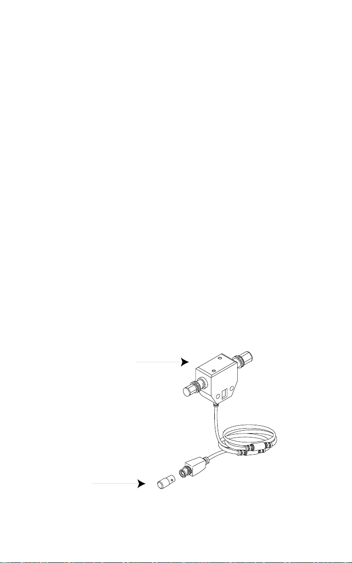
Installing the Tap Terminator
1. Remove the dust cap from the exis ting tap.
2. Install the tap terminator over the exposed end of dummy as shown
below.
ControlNet Ex Tap
1797-TCAP Tap
Terminator
FLEX Ex is a trademark of Rockwell Automation. 1797-5.30 - September 1999
30131-M
Page 2
2 ControlNet Ex Tap Terminator Installation Instructions
ControlNet Ex System Diagram
C.
o
Zone 1 or 2, IIC
Flexbus Uo= 5.4V,
3
,
µmA, Po=2.16W,
µF, L o= 1 0µH
Co=65
Io=400
any IS device with entity
concept parameters V
.
Node 4 ... 48
1797-ACNR15
,
max
1
max
) appropriate for
i
, L
i
C
max
I
connection to associated
apparatus with entity
concept parameters
listed in ta ble 1
.
2
.
.
1
hazardous (classified) location
) appropria te for
µmA, Po=2.16W,
i
µF, L o=1 0µH
Node 2
Class I, Zones 1 and 2, Groups IIC, IIB, IIA
1797-RPFM 1797-RPFM
1797-RPA
The ambient temperature rang e of the ControlNet Ex system is -20 to + 70
Class I Division 1 and 2, Groups A, B, C, D
.
.
.
.
Flexbus Uo=5.4V,
.
.
.
Io=400
Co=65
Node 3
1797-ACNR15
power supply Vmax or
ControlNet Ex
BNC Uo=5.4V,
, L
i
ControlNet Ex
C
max
I
any IS device with entity
concept parameters V
.
.
Ch2
Ch1
120nF, Li=0
Ui=9.5V, Imax or Ii=1A,
Ci<
to any approved device
500kHz
Io=201mA,
F>
BNC Uo=5.4V,
connection to associated
apparatus with entity
concept parameters
listed in table 1
.
1
.
54
ControlNet Ex
BNC Uo=5.4V,
fiber optic cable
Ch2
2
Ch1
1
<9.5V
o
<1A
o
or associated apparatus
with Entity Concept
parameters of V
and I
1
<1A
sc
120nF, Li=0
<9.5V and I
oc
CNet Ex
power supply Vmax or Ui=9.5V,
Imax or Ii=1A, Ci<
to any approved device or associated
apparatus with Entity Concept
parameters of V
ChBChA
500kHz
1
Io=160mA,
F>
<1A
o
120nF, Li=0
<9.5V and I
o
ChB
to any approved device or associated
apparatus with Entity Concept
parameters of V
power supply Vmax or Ui=9 .5V,
Imax or Ii=1A, Ci<
ChA
500kHz
Io=160mA,
F>
2
trk trm
tap
ControlNet Ex
2
cable
coax trunk
tap
ControlNet Ex
Zone 1 or 2, IIC
hazardous (classified) location
2
tap
ControlNet Ex
CNet Ex
tap trm
tap
ControlNet Ex
Node 1
CNet Ex
trk trm
30670
Class III, Division 1 and 2
Class II, Division 1 and 2, Groups E, F, G
Class I, Zones 1 and 2, Groups IIC, IIB, IIA
Class I Division 1 and 2, Groups A, B, C, D
cable
coax trunk
2
is <5mW/mm
(e.g. Hewlett Packard
1786-RPFM or any associated
emitting diode output
apparatus where the light
HFBR-1312 or HFBR-1414).
nonhazardous location
1797-5.30 - September 1999
Zone 0, 1 or 2, IIC
Groups A, B, C, D
Groups IIC, IIB, IIA
Class I Division 1 and 2,
Class I, Zones 0, 1 and 2,
hazardous (classified) location
Groups E, F, G
Class II, Division 1 and 2,
Class III, Division 1 and 2
Page 3
ControlNet Ex Tap Terminator Installation Instructions 3
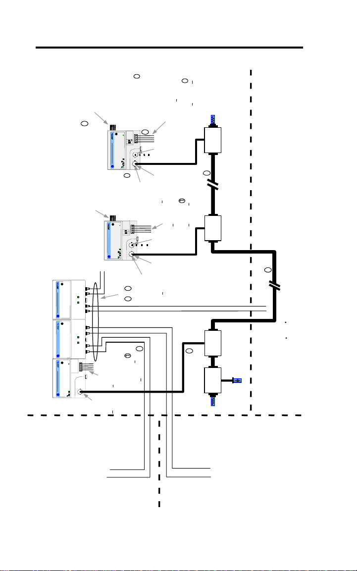
Describing the ControlNet Ex System Diagram
A maximum of 48 ControlNet ExTM nodes may be connected together by
820ft (250m) of coax cable and 48 taps. The distance to increases to 3280ft
(1000m) when you use only 2 taps. See the table below for more
information.
The fiber media of the 1797-RPFM can be installed in a hazardous location
(Zone 0, 1 or 2; Class I, Zones 0, 1, and 2; Class I, Divisio n 1 and 2; Class
II, Division 1 and 2; Class III, Division 1 and 2) to connect two
1797-RPFM modules or they can be installed through different locations
into the non-hazardous location to connect the 1797-RPFM with any
approved as sociated appar atus.
All cables and fibe r media that are not light blue must be marked as I S
using the 1797-EXMK marking kit or other locally approved IS
identification and/or segregation method.
During the installation of the Co ntrolNet Ex system, all m etallic parts must
be isolated to prevent an earth connection (high voltage withstanding of
isolating material must be > 500V ac).
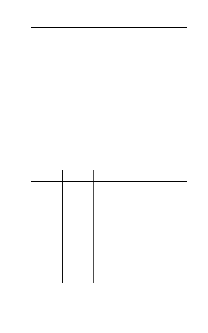
System
Diagram Name
1797-RPA 1797-RPA ControlNet Ex
1797-RPFM 1797-RPFM ControlNet Ex Fiber
1797-ACNR15 1797-ACNR15 Redundant Media
CNet Ex Tap Trm 1797-TCAP ControlNet Ex Tap
Catalog
Number
Catalog Name Description
Modular Repeater
Adapter
Repeater Module,
Medium Distance
ControlNet Ex
Adapter
(Dummy) Terminator
Represents one ControlNet Ex
node and must be connected
to a coax trunk cable by
1797-TPx
Allows connection of a
maximum of two devices per
1797-RPA and is powered
directly by 1797-RPA
Represents one ControlNet Ex
node and must be connected
to a coax trunk cable by
1797-TPx -each one with two
redundant output channels
that are connected to different
ControlNet Ex networks (coax
cables and 1797-TPx)
Represents one ControlNet Ex
node and is a simple
capacitor (56pF) with a coax
connector
1797-5.30 - September 1999
Page 4

4 ControlNet Ex Tap Terminator Installation Instructions
System
Diagram Name
ControlNet Ex
Tap
Catalog
Number
Catalog Name Description
1797-TPx ControlNet Ex Coax
Tap
Four types of connections
available: S (straight t-tap), R
(right angle t-tap), YS (straight
y-tap), and YR (right angle
y-tap) - a maximum of 48
taps can be connected
together by coax trunk cable
CNet Ex Trk Trm 1797-XT ControlNet Ex Trunk
Terminator
Coax Trunk
Cable
1797-RG6 Quad-Shield, RG-6
75Ω Coax Trunk
Cable
Simple resistor (75Ω) with
coax connector that must be
on each end of the ControlNet
Ex coax trunk for termination
Maximum (functional) length
between 2 1797-TPx is
3280ft (1000m) - each
1797-TPx reduces the
(functional) coax cable length
by 53.4ft (16.3m)
None None Standard Coax Trunk
Cable BNC Couplers
Different standard cable
couplers, 90
o
, 180o, etc.
Certified Equivalent ControlNet Ex System Diagram Items
You may use these items as equivalents for the items shown on the system
diagram.
System Diagram Name Catalog Number Source
Coax Trunk Cable 1797-RG6 Allen-Bradley
1
3092A
3092A with blue jacket Belden Wire & Cable Co.
1 Belden Wire & Cable 1189A may be used, but with functional loss of communication
distance and/or nodes.
Belden Wire & Cable Co.
1797-5.30 - September 1999
Page 5

ControlNet Ex Tap Terminator Installation Instructions 5
UL, cUL I/O Entity Parameters and Requirements
Tab l e 1
Ter m i nals Vt (V) It (mA) Groups C
Male Bus
Connector
The entity concept allows interconnection of intrinsically safe
5.8 400 A-G 3.0 3.0
apparatus with associated apparatus not specifically examin ed in
combination as a system when t he approved values of Voc and Isc or Vt and
I
of the associated apparatus are less th an or equal to V
t
intrinsically safe apparatus and the approved values of C
associated apparatus are greater than C
+ C
i
cable
for the intrinsically safe apparatus.
ó
Wiring methods must be in accordance with the National Electric
Code, ANSI/NFPA 70, Article 504 and 505 or the Canadian Electric Code
CSA C22.1, Part 1, Appendix F. For additional information refer to ANSI/
ISA RP12.6.
ì
WARNING: Substitution of components may impair intrinsic safety.
AVERTISSEMENT: La substitution de composant peut compromettre la
securite intrinseque.
ö
If fiber optic cable is provided with a meta l shield, it must be connected
to a dedicated intrinsic safety ground in the non-hazardous location and
tied back in the haza rdous location or be c onnected to a ground in the
hazardous location and tied back in the non-hazardous location.
(µF) La (µH)
a
max
and Li + L
and I
and La of the
a
cable
of the
max
respectively
ú
The glass fiber mus t ha ve a minimum diameter of 6µm.
1797-5.30 - September 1999
Page 6

6 ControlNet Ex Tap Terminator Installation Instructions
Installation in Zone 1
ATTENTION: This tap terminator cannot be used in an
intrinsically safe environment after it has been exposed to
non-intrinsically safe signals.
!
Make certain th at you only connect ControlNet Ex products to other
intrinsically safe system products to maintain the integrity of the
intrinsically-safe system.
41307
Electrostatic Charge
Protect the system against electrostatic charge. Post a sign near the adapter:
Attention! Avoid electrostatic charge. For your conve nie n ce , a sign
which can be cut out is included in this installation instruction.
European Community Directive Compliance
If this product has the CE mark it is approved for installation within the
European Community or EEA regions. It has been designed and tested to
meet the following directives.
EMC Directive
This product is tested to meet the Council Directive 89/336/EC
Electromagnetic Compatibility (EMC) by applying the following
standards, in whole or in part, documented in a technical construction file:
• EN50081-2
EMC - Generic Emission Standard, Part 2 - Industrial Environment
• EN50082-2
EMC - Generic Immunity Standard, Part 2 - Industrial Environment
1797-5.30 - September 1999
Page 7

ControlNet Ex Tap Terminator Installation Instructions 7
This product is intended for use in an industrial environment.
Ex Directive
This product is tested to meet the Council Dir ectiv e 94 /9 EC (ATEX 100a)
Equipment and Protective Systems Intended for Use in Potentially
Explosive Atmospheres by applying the following standards:
• EN50014:1992, Electrical Apparatus for Potentially Explosive
Atmospheres
• EN50020:1994, Electrical Apparatus for Potentially Explosive
Atmospheres - Intrinsic Safety “i”
• EN50039:1980, Electrical Apparatus for Potentially Explosive
Atmospheres - Intrinsically Safe Electrical Systems “i”
• pr EN50284:1997, Special requirements for construction, test, and
marking of electrical apparatus of equipment group II, category 1 G
Important: For detailed certification information, refer to the FLEX Ex
System Certification Reference Manual, public ation
1797-6.5.6.
Attention: Avoid electrostatic charge.
1797-5.30 - September 1999
Page 8

ControlNet is a trademark of ControlNet International.
ControlNet Ex is a trademark of Rockwell Automation.
Publication 1797-5.30 - September 1999 PN 957236-26
© (1999) Rockwell International Corporation.Printed in USA
 Loading...