

Page 1

Installation Instructions
ControlNet Ex Modular Repeater Adapter &
Fiber Repeater Module
Catalog Numbers 1797-RPA and 1797-RPFM
Contents
For Information About See Page
Important User Information 2
About the ControlNet Ex Fiber Repeater Hub 4
DIN-Rail Mount the 1797-RPA and -RPFM 5
Installation in Zone 1 for CENELEC 8
Installation in Division 1/Zone 1 for UL, C-UL and FM 8
Electrostatic Charge 9
European Community (EC) Directive Compliance 9
Inputs/Outputs 11
Wire the Modules 12
Describing the ControlNet Ex System Diagram 14
Certification Specific ControlNet Ex System Diagrams 17
CENELEC Installation Label 18
CENELEC ControlNet Ex System Diagram 19
UL, C-UL ControlNet Ex System Diagram 20
FM ControlNet Ex System Diagram 22
Module Indicators 24
About the Mounting Kit 26
Repair 26
Specifications - 1797-RPA 27
Specifications - 1797-RPFM 29
Mounting Dimensions 31
Publication 1797-5.15 - June 2010
Page 2
2 ControlNet Ex Modular Repeater Adapter & Fiber Repeater Module
WARNING
IMPORTANT
ATTENTION
SHOCK HAZARD
BURN HAZARD
Important User Information
Solid state equipment has operational characteristics differing from those of electromechanical
equipment. Safety Guidelines for the Application, Installation and Maintenance of Solid State Controls
(Publication SGI-1.1 available from your local Rockwell Automation sales office or online at
http://www.literature.rockwellautomation.com) describes some important differences between solid
state equipment and hard-wired electromechanical devices . Because of this dif fe ren ce , and als o becaus e
of the wide variety of uses for solid state equipment, all persons responsible for applying this equipment
must satisfy themselves that each intended application of this equipment is acceptable.
In no event will Rockwell Automation, Inc. be responsible or liable for indirect or consequential damages
resulting from the use or application of this equipment.
The examples and diagrams in this manual are included solely for illustrative purposes. Because of the
many variables and requirements associated with any particular installation, Rockwell Automation, Inc.
cannot assume responsibility or liability for actual use based on the examples and diagrams.
No patent liability is assumed by Rockwell Automation, Inc. with respect to use of information, circuits,
equipment, or software described in this manual.
Reproduction of the contents of this manual, in whole or in part, without written permission of Rockwell
Automation, Inc. is prohibited.
Throughout this manual we use notes to make you aware of safety considerations.
Identifies information about practices or circumstances that can cause an explosion in a
hazardous environment, which may lead to pers onal injury or death, property damage, or
economic loss.
Identifies information that is critical for successful application and understanding of the
product.
Identifies information about practices or ci rcumstances that can lead to pe rsonal injury or
death, property damage, or economic loss. Attentions help you identify a hazard, avoid a
hazard, and recognize the consequence.
Publication
Labels may be located on or inside t he equipment to alert people that danger ous v olt age
may be present.
Labels may be located on or inside the equipment to alert people that surfaces may be
dangerous temperatures.
1797-5.15 - June 2010
Page 3
ATTENTION
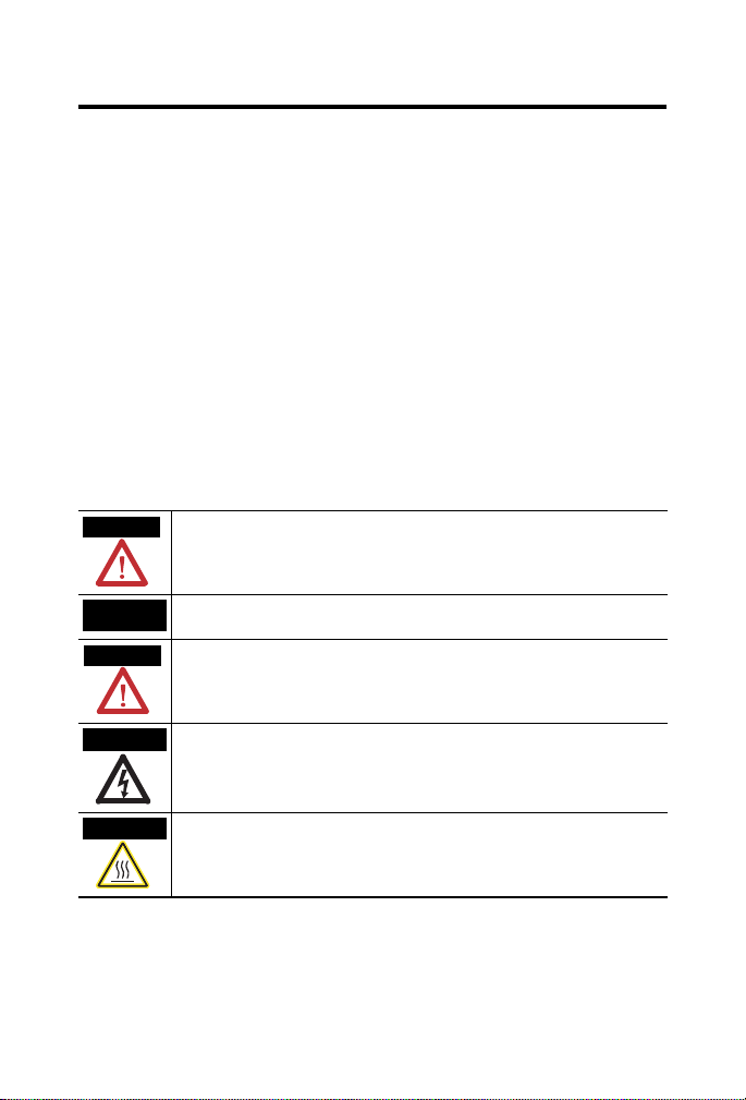
41163
Repeater
Backplane
Connector
Module Locking Tab
Power and
Common Connections
Indicators
Backplane Connector Cover
1797-RPA
Label Here
Do not remove
unless connecting to
1797-RPFM.
ControlNet Ex
Tap Drop BNC
Connector With
Insulator Boot
ControlNet Ex Modular Repeater Adapter & Fiber Repeater Module 3
Environment and Enclosure
This equipment is considered Group 1, Class A industrial
equipment according to IEC/CISPR Publicatio n 11. Without
appropriate precautions, there may be potential diffic ulties
ensuring electromagnetic compatibility in other environm ents
due to conducted as well as radiated disturbance.
This equipment is supplied as open-type equipment. It must be
mounted within an enclosure that is suit ab ly designed for those
specific environmental conditions that will be present and
appropriately designed to prevent personal injury resulting from
accessibility to live parts. The interior of the enc losure must be
accessible only by the use of a tool. Subsequent sections of this
publication may contain additional information regarding
specific enclosure type ratings that are required to comply with
certain product safety certifications .
1797-RPA
COMM
MODULE
STATUS
STATUS
REPEATER
ADAPTER
PWR
1
2
3
4
+V
-V
+V
-V
Publication
1797-5.15 - June 2010
Page 4
4 ControlNet Ex Modular Repeater Adapter & Fiber Repeater Module
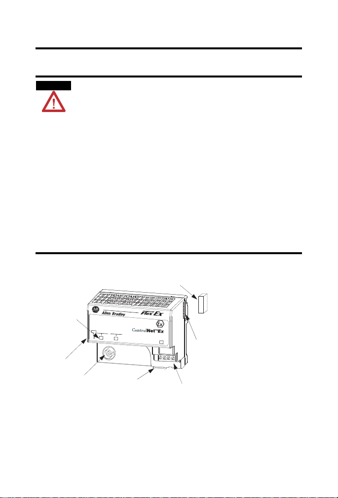
41267
Repeater
Backplane
Connector
Module Locking Tab
Backplane Connector Cover
1797-RPFM
Label Here
Do not remove
unless connecting to
1797-RPFM.
1797-RPFM
Chan 1
Recv
Chan 2
Xmit
Recv
Xmit
About the ControlNet Ex Fiber Repeater Hub
Use the repeater adapter (1797-RPA ) and the fiber module (1797-RPFM)
together to form a repeater hub within the hazardous area to extend the
length of the ControlNet Ex segments to interlink systems all operating
within the area.
The 1797-RPA repeater adapter, configured with at least one repeater adapter,
functions as the intelligent starter block for a multiport repeater. The
1797-RPFM is a nonintelligent fiber-to-backplane conversion device,
converting glass-fiber infra red LED media signals to ba ckplane signals for use
by the 1797-RP A.
A maximum of two 1797-RPFM modules may be used with one 1797-RPA
adapter.
Publication
1797-5.15 - June 2010
Page 5
ControlNet Ex Modular Repeater Adapter & Fiber Repeater Module 5
ATTENTION
ATTENTION
41167
41166
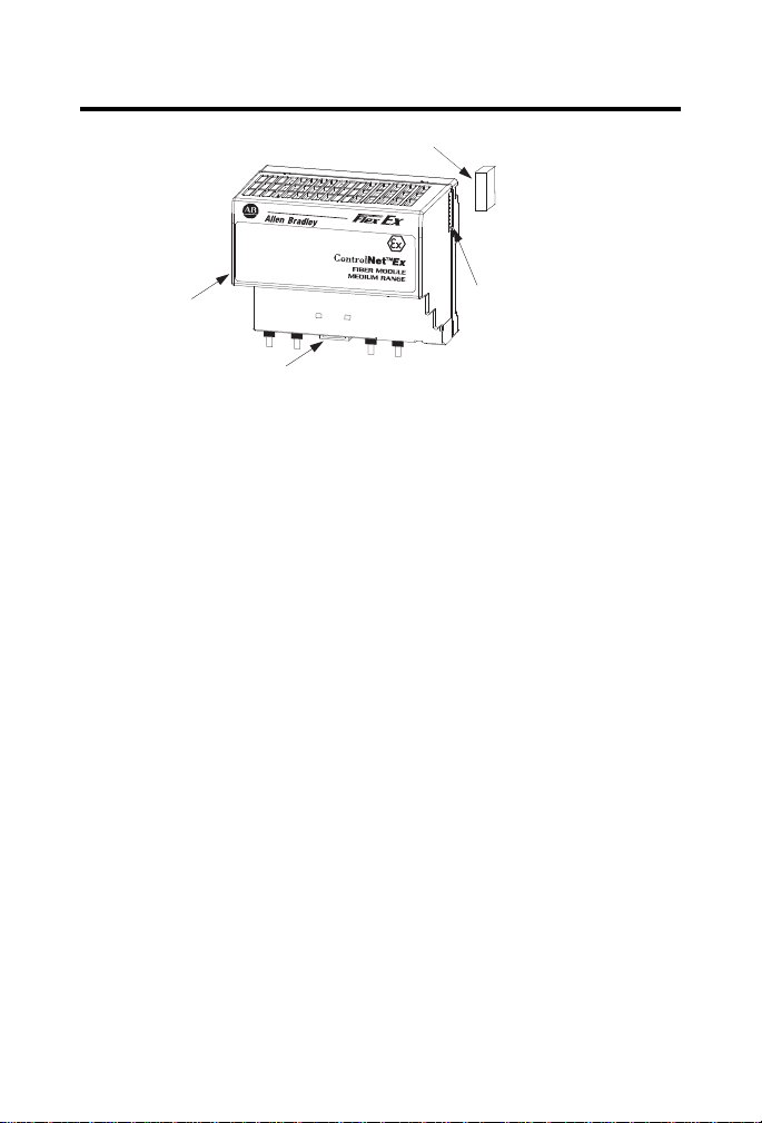
DIN-Rail Mount the 1797-RPA and -RPFM
Refer to Mounting Dimensions on page 31. For panel mounting information,
see publication 1794-5.13.
This product is grounded through the DIN rail to the dedicated
intrinsic safety ground. Use zinc-plated yellow-chromate steel
DIN rail to assure proper grounding. The use of other DIN rail
materials (such as aluminum or plastic) that can corrode, oxidize ,
or are poor conductors, can result in improper or intermittent
grounding.
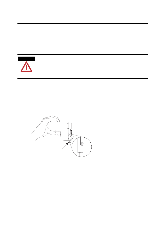
1. Position the module on a 35 x 7.5 mm DIN rail (A-B part number
199-DR1) at approximately a 30o angle.
The DIN rail or mounting bracket must be appropriately
connected to the dedicated intrinsic safety gr ound.
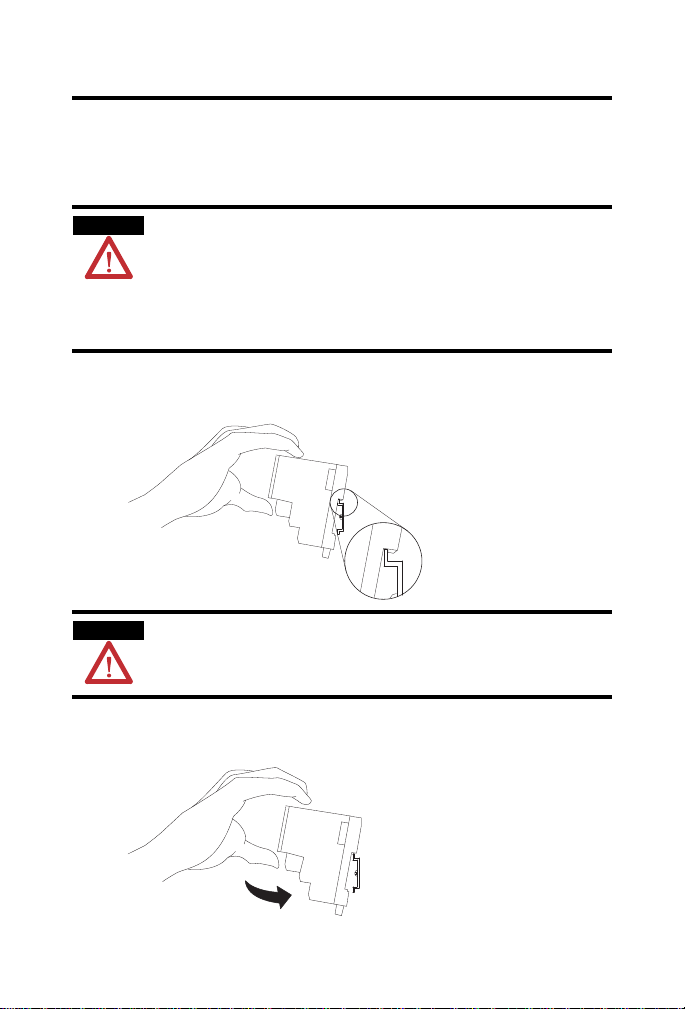
2. Hook the lip on the rear of the adapter onto the top of the DIN rail,
and rotate the module onto the rail.
Publication
1797-5.15 - June 2010
Page 6
6 ControlNet Ex Modular Repeater Adapter & Fiber Repeater Module
ATTENTION
41168
3. Press the adapter down onto the DIN rail until flush.
The locking tab should snap into position and lock the module to the
DIN rail.
Make certain that the adapter and fiber modules are secured
together with DIN rail anchors. Failure to do so may result in
the loss of communications, cause damage to the modules, or
both.
4. If the adapter does not snap into position, use a screwdriv er or similar
device to move the locking t ab down while pressing the module flush
onto the DIN rail.
Release the locking tab to lock the module in place. If necessary, push
up on the locking tab to lock.
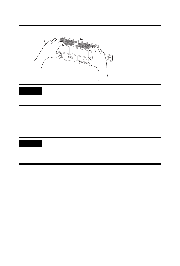
5. Remove the adapter backplane connector cover.
6. Follow steps 1 to 4 to attach fiber modules to the DIN rail.
7. Once attached to the DIN rail, slide fiber modules to the left to mate
with the adapter.
Publication
1797-5.15 - June 2010
Page 7
ControlNet Ex Modular Repeater Adapter & Fiber Repeater Module 7
IMPORTANT
IMPORTANT
41169
A DIN-rail end anchor (A-B part number 1492-EA35) must
be used on the left side of the adapter and on the right side of
the fiber module to keep the units from moving.
8. Make sure the last fiber module has its backplane conne ctor cover in
place.
9. Connect the adapter wiring as shown below in the Wi rin g sec ti on .
You can only attach two me di a modules to the repeater
adapter. If you exceed the module limit , you may cause
damage to the adapter or fiber modules and void the IS
certification.
Publication
1797-5.15 - June 2010
Page 8
8 ControlNet Ex Modular Repeater Adapter & Fiber Repeater Module
WARNING
WARNING
0102
ControlNet Ex System
Allen-Bradley
Attention!
Avoid electrostatic charging!
-200C <= Ambient Temperature <= +700C
1 Allen-Bradley Dr.
Mayfield Hts., OH USA
DMT 99 ATEX E 065 X
II (1)2G Ex ia ib IIC
41307
Installation in Zone 1 for CENELEC
Modules must not be exposed to the environ me nt . Provide a suitable metal
enclosure. A label with this system marking must be attached near the main
components of the system. If the system is installed in a cabinet, this label
must be fixed inside the cabinet.
Modules cannot be used in an intrinsically safe environment
after they have been exposed to nonintrinsically safe signals.
Installation in Division 1/Zone 1 for UL, C-UL and FM
This adapter must not be exposed to the environment. Provide a suitable
metal enclosure. This adapter has a protection factor of IP20.
Make certain that you only connect ControlNet Ex adapters to other
intrinsically safe system modules to maintain the integrity of the
intrinsically-safe backplane.
Publication
This adapter cannot be used in an intrinsically safe environment
after it has been exposed to nonintrinsically safe signals.
1797-5.15 - June 2010
Page 9

ControlNet Ex Modular Repeater Adapter & Fiber Repeater Module 9
Electrostatic Charge
Protect the system against electrostatic charge. Post a sign near this module:
WARNING Avoid electrostatic charging.
ADVERTÊNCIA! PREVENIR CONTRA O ACÚMULO DE CARGA
ELETROSTÁTICA.
For your convenience, a sign that can be cut out is included in this installation
instruction.
European Community (EC) Directive Compliance
If this product has the CE mark it is approved for installation within the
European Community or EEA regions. It has been designed and tested to
meet the following directives.
EMC Directive
If this product has the CE mark it is approved for installation within the
European Community or EEA regions. It has been designed and tested to
meet the following directives.
These products are tested to meet the Council Directive 2004/108/EC by
applying the following standards:
EN 61000-6-4:2007, Electromagnetic Compatibility (EMC) - Part 6-4:
Generic Standard for Industrial Environments (Class A)
EN 61000-6-2:2005, Electromagnetic Compatibility (EMC) - Part 6-2:
Generic Standards - Immunity for Industrial Environments
EN61326-1:2006 (Industrial), Electrical Equipment For
Measurement, Control, and Laboratory Use - Industrial EMC
Requirements
Publication
1797-5.15 - June 2010
Page 10

10 ControlNet Ex Modular Repeater Adapter & Fiber Repeater Module
ATEX Directive
These products are tested in conjunction with associated I/O modules to
meet the Council Directive 94/9/EC (ATEX) Equipment and Protective
Systems Intended for Use in Potentially Explosive Atmospheres by applying
the following standards.
EN60079-11:2007, Explosive atmospheres - Part 11 : equipment
protection by intrinsic safety "i"
EN60079-0:2006, Electrical apparatus for explosive gas atmospheres -
Part 0 : general requirements
EN 60079-26 : 2004, Electrical apparatus for explosive gas
atmospheres - Part 26 : construction, test and marking of Group II
Category 1 G electrical apparatus
EN61241-0 : 2006, Electrical apparatus for use in the presence of
combustible dust - P art 0: General requirements
EN61241-11:2006, Electrical apparatus for use in the presence of
combustible dust – P a rt 11: Prot ection by intrinsic safety 'iD'
UL, C-UL Compliance
If this product has the UL/C-UL mark, it has been designed, evaluated,
tested, and certified to meet the following standards:
UL 913, 1988, Intrinsically Safe Apparatus and Associated Apparatus
for Use in Class I, II, and III Division 1, Hazardous (Classified)
Locations
UL 1203, Explosion-Proof and Dust-Ignition-Proof Electrical
Equipment for Use in Hazardous (Classified) Locations
UL 2279, Electrical Equipment for Use in Class I, Zone 0, 1, and 2
Hazardous (Classified) Locations
UL 61010, UL Standard for Safety Electrical Equipment For
Measurement, Control, and Laboratory Use; Part 1: General
Requirements
CSA C22.2 No. 157-92, Intrinsically Safe and Non-Incendive
Equipment for Use in Hazardous Locations
CSA C22.2 No. 30-M1986, Explosion-Proof Enclosures for Use in
Class I Hazardous Locations
Publication
1797-5.15 - June 2010
Page 11

ControlNet Ex Modular Repeater Adapter & Fiber Repeater Module 11
41309
1797-RPA
Power
Supply
+V
-V
Channel
Network Bus
uCuC
Fiber Hub Bus
CSA-E79-0-95, Electrical Apparatus for Explosive Gas Atmospheres,
Part 0: General Requirements
CSA-E79-11-95, Electrical Apparatus for Explosive Gas
Atmospheres, Part 11: Intrinsic Safety “i”
CSA C22.2 No. 14-95, Industrial Control Equipment
FM Compliance
If this product has the FM mark, it has been designed, e valuated, tested, and
certified to meet the following standards:
FM C1. No.3600:1998, Electrical Equipment for Use in Hazardous
(Classified) Locations General Requirements
FM C1. No.3610:1999, Intrinsically Safe Apparatus and Associated
Apparatus for Use in Class I, II, III Division 1 Hazardous (Classified)
Locations
FM C1. No.3615:1989, Explosionproof Electrical Equipment General
Requirements
FM C1. No.3810:1989, 1995, Electrical and Electronic Test,
Measuring and Process Control Equipment
ANSI/NEMA 250, 1991, Enclosures for Electrical Equipment
Inputs/Outputs
Do not apply any nonintrinsically safe signals to the adapter or fiber modules.
When using as an intrinsically safe electrical apparatus according to EN
60079-11, the European directives and regulations must be followed
.
Publication
1797-5.15 - June 2010
Page 12

12 ControlNet Ex Modular Repeater Adapter & Fiber Repeater Module
IMPORTANT
IMPORTANT
41310
1797-RPFM
Channel 1
Channel 2
Receiver
Receiver
Transmitter
Transmitter
Bus
Proc
Fiber Hub Bus
41170
ControlNet Ex
Coax Tap
Insulator Ring
Installed
Wire the Modules
1. Connect the ControlNet Ex tap drop cable to the connector after
removing the insulator boot.
The tap drop BNC must have its insulator ring in position
when inserted in the adapter BNC connector.
2. Connect the fiber media to the fiber module by selecting either the left
or right set of receive and transmit ports and attaching the receive and
transmit fibers, as appropriate.
Publication
Make note of which fiber is receive and which is transmit as
they must be interchanged at the opposite end.
1797-5.15 - June 2010
Page 13

ControlNet Ex Modular Repeater Adapter & Fiber Repeater Module 13
Receive
Transmit
Transmit
Receive
41311
41297
Control
REPEATER ADAPTER
12
+V -V +V -V
1797 - RPA
Net Ex
PWR
43
B-A
Allen-Bradley
QUALITY
.
.
1
Recv Xmit Recv Xmit
B-A
Allen-Bradley
1797 - RPFM
Net Ex
Control
FIBER MODULE
MEDIUM RANGE
Chan 1
.
Chan 2
QUALITY
Comm
Module
Status
Status
.
B-A
Allen-Bradley
QUALITY
Comm
Module
Status
Status
.
Control
REPEATER ADAPTER
12
+V -V +V -V
1797 - RPA
Net Ex
PWR
43
B-A
Allen-Bradley
QUALITY
.
.
1
Recv Xmit Recv Xmit
Chan 1
Chan 2
3. Apply +V and -V power to the adapter through a removable terminal
block from the Ex power supply.
+V -V +V -V
+V -V +V -V
Screw terminals and spring terminals are provided.
4. Strip the +V and -V wires to a length so no bare conductor shows
after inserting the wires into position.
1797 - RPFM
Net Ex
Control
FIBER MODULE
MEDIUM RANGE
.
Publication
1797-5.15 - June 2010
Page 14

14 ControlNet Ex Modular Repeater Adapter & Fiber Repeater Module
WARNING
IMPORTANT
5. If you are using the spring terminals of the plug, insert a screwdriver
into the slot and carefully pry until the spring clamp opens to accept
the wire.
Do not use any unused terminals on this adapter. Using these
terminals as supporting terminals can result in damage to the
module and unintended operation of your system.
Make certain that you power this adapter with an intrinsically
safe power supply. Do not exceed the va lues listed in the
specifications for this adapter.
Do not remove or replace a module when power is applied.
Interruption of the bus can result in unintended operation or
machine motion.
If you connect or disconnect wiring while the field-side power is
on, an electrical arc can occur. This could cause an explosion in
hazardous location installations. Be sure that power is removed
or the area is nonhazardous before proceeding.
Make sure all fiber modules are attached and secured prior to
applying intrinsically safe power to the adapter. Failure to do
so may cause damage to the adapter and modules.
Describing the ControlNet Ex System Diagram
A maximum of 48 ControlNet Ex nodes may be connected together by 250 m
(820 ft) of coax cable and 48 taps. The distance to increases to 1000 m (3280
ft) when you use only 2 taps. See the table below for more information.
The fiber media of the 1797-RPFM can be installed in a hazardous location
(Zone 0, 1 or 2; Class I, Zones 0, 1, and 2; Class I, Division 1 and 2; Class II,
Division 1 and 2; Class III, Division 1 and 2) to connect two 1797-RPFM
modules or they can be installed through different locations into the
nonhazardous location to connect the 1797-RPFM with any approved
associated apparatus.
Publication
1797-5.15 - June 2010
Page 15

ControlNet Ex Modular Repeater Adapter & Fiber Repeater Module 15
All cables and fiber media that are not light blue must be marked as IS using
the 1797-EXMK marking kit or other locally approved IS identification or
segregation method.
During the installation of the ControlNet Ex system, all metallic parts must be
isolated to prevent an earth connection (hi gh voltage withstandi ng of isolating
material must be > 500V ac).
Publication
1797-5.15 - June 2010
Page 16

16 ControlNet Ex Modular Repeater Adapter & Fiber Repeater Module
System
Diagram Name
Catalog
Number
Catalog Name Description
1797-RPA 1797-RPA ControlNet Ex
Modular Repeater
Adapter
1797-RPFM 1797-RPFM ControlNet Ex Fiber
Repeater Module,
Medium Distance
1797-ACNR15/B 1797-ACNR15/B Redundant Media
CNet Ex Tap Trm 1797-TCAP ControlNet Ex Tap
ControlNet Ex
Tap
1797-TPx ControlNet Ex Coax
CNet Ex Trk Trm 1797-XT ControlNet Ex Trunk
ControlNet Ex
Adapter
(Dummy) Terminator
Tap
Terminator
Coax Trunk Cable 1786-RG6 Quad-Shield, RG-6
75
Coax Trunk
Cable
None None Standard Coax Trunk
Cable BNC Couplers
Represents one ControlNet Ex
node and must be connected
to a coax trunk cable by
1797-TPx
Allows connection of a
maximum of two devices per
1797-RPA and is powered
directly by 1797-RPA
Represents one ControlNet Ex
node and must be connected
to a coax trunk cable by
1797-TPx -each one with two
redundant output channels
that are connected to different
ControlNet Ex networks (coax
cables and 1797-TPx)
Represents one ControlNet Ex
node and is a simple capacitor
(56 pF) with a coax connector
Four types of connections
available: S (straight t-tap), R
(right angle t-tap), YS (straight
y-tap), and YR (right angle
y-tap) - a maximum of 48 taps
can be connected together by
coax trunk cable
Simple resistor (75 ) with
coax connector that must be
on each end of the ControlNet
Ex coax trunk for termination
Maximum (functional) length
between 2 1797-TPx is 1000 m
(3280 ft) - each 1797-TPx
reduces the (functional) coax
cable length by 16.3 m (53.4 ft)
Different standard cable
couplers, such as 90
o
, 180o.
Publication
1797-5.15 - June 2010
Page 17

ControlNet Ex Modular Repeater Adapter & Fiber Repeater Module 17
Certified Equivalent ControlNet Ex System Diagram Items
You may use these items as equivalents for the ite ms shown on the system
diagram.
System Diagram Name Catalog Number Source
1797-RPA 1797-RPA Allen-Bradley
1797-RPFM 1797-RPFM Allen-Bradley
1797-ACNR15 1797-ACNR15 Allen-Bradley
Coax Trunk Cable
(1)
ControlNet Ex Tap 1797-TPx Allen-Bradley
CNet Ex Trk Trm 1797-XT Allen-Bradley
CNet Ex Tap Trm 1797-TCAP Allen-Bradley
1 In addition to these cable types, the following specification can be followed to allow additional
types:
Cable Impedance = 75 + 3
Cable Capacitance = <5.94 nF per 100 m
Cable Resistance = >9.08 per 100 m
Cable Attenuation 0.2 MHz > 0.93 dB/100 m 5 MHz > 1.39 dB/100 m
(-20…70 °C) 0.5 MHz > 0.95 dB/100 m 10 MHz > 1.86 dB/100 m
2 Belden Wire & Cable 1189A may be used, but with functional loss of communication distance,
nodes, or both.
1786-RG6 Allen-Bradley
3092A
(2)
Belden Wire & Cable Co.
3092A with blue jacket Belden Wire & Cable Co.
1 MHz > 1.07 dB/100 m 20 MHz > 2.73 dB/100 m
2 MHz > 1.16 dB/100 m 50 MHz > 4.33 dB/100 m
Certification Specific ControlNet Ex System Diagrams
The following pages include certification specific ControlNet Ex system
diagrams and notes pertaining to these diagrams. Select either CENELEC,
UL, C-UL, or FM and follow the requirements of that diagram as you
configure and install your system.
Publication
1797-5.15 - June 2010
Page 18

18 ControlNet Ex Modular Repeater Adapter & Fiber Repeater Module
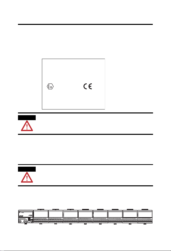
CENELEC Installation Label
A label with this system marking must be attached near the main components
of the system. If the system is installed in a cabinet, this label must be fixed
inside the cabinet.
Allen-Bradley
1 Allen-Bradley Dr.
Mayfield Hts., OH USA
ControlNet Ex System
DMT 99 ATEX E 065 X
II (1)2G Ex ia ib IIC
-200C <= Ambient Temperature <= +700C
Attention!
Avoid electrostatic charging!
CENELEC 1797-RPA, -RPFM I/O Entity Parameters
Terminals Uo (V) Io (mA) Groups Co (F) Lo (H)
0102
Male Bus
Connector
Publication
5.4 400 IIB/IIC 65 10
1797-5.15 - June 2010
Page 19

ControlNet Ex Modular Repeater Adapter & Fiber Repeater Module 19
1
.
.
.
.
.
CNet Ex
trk trm
30670CE
ControlNet Ex
tap
Safe Area
Hazardous Area
Zone 0
Node 1
ControlNet Ex
tap
ControlNet Ex
tap
ControlNet Ex tap
CNet Ex
tap trm
Ci<
68 pF
Li negl.
ChB
Uo=5.4V,
Io=160 mA,
F
-3
>500 kHz
Flexbus
Uo=5.4V,
Io=400 mA,
Po=2.16 W,
Co=65 F,
Lo=10 H
Ch0
fiber
The Coax Trunk Cable is permitted to have a minimum length of 1,000m with only 2 connected ControlNet Ex
Taps dropping to only 250m with the maximum allowed connected ControlNet Ex Taps of 48.
Node 4 ... 48
Node 3
The ControlNet Ex System is an intrinsically safe system according to EN 50039. When installing the system, the
certificate of conformity and the national installation regulations must be heeded. The components of the
ControlNet Ex system and the interconnections are shown on the installation drawing (A-B Pub. 1797-6.5.6).
For the transmittal between the safe area and the hazardous area only optical glass-fibers are permit t ed. The
diameter of a single glass-fiber must be >6um. The power density of the transmitter diode must be <5mW/mm
2
.
Protect the system against electrostatic charge. Post a sign near the main components of the system: Attention!
Avoid electrostatic charge.
1797-ACNR15/* or
RSD-GW-Ex2.CN
1797-ACNR15/* or
RSD-GW-Ex2.CN
Flexbus
Uo=5.4V,
Io=400 mA,
Po=2.16 W,
Co=65 F,
Lo=10 H
Power Supply
Ui=9.5V,
Ii=1 A,
Ci=<
120 nF,
Li=negligible
ChA
Uo=5.4V,
Io=160 mA,
F
-3
>500 kHz
Power Supply
Ui=9.5V,
Ii=1 A,
Ci=<120 nF,
Li=negligible
ChB
Uo=5.4V,
Io=160 mA,
F
-3
>500kHz
ChA
Uo=5.4V,
Io=160 mA,
F
-3
>500 kHz
75 Ohm
1W
Ci negl.
Li negl.
The ambient temperature range of the ControlNet Ex system is -20 to +70
o
C.
Near the main components of the system a plate with the system marking must be attached. If
the system is installed in a cabinet the plate must be fixed on the inside of the cabinet door.
*RG6-CNet is defined as: Cable Impedance=75 Ohm + or -3 Ohm
Cable Capacitance<
6nF per 100 m
Cable Resistance>9.08 Ohm per 100 m
Cable Attenuation (-20to+70
o
C) 0.2 MHz > 0.93 dB/100 m 5 MHz > 1.39 dB/100 m
0.5 MHz >
0.95 dB/100 m 10 MHz >1.86 dB/100 m
1 MHz >
1.07 dB/100 m 20 MHz > 2.73 dB/1 00 m
coax trunk cable
coax trunk cable
Cable type 1189A,
3092A, or 3092A Blue
from manufacturer
Belden Wire or type
RG6-CNet*
CNet Ex
trk trm
75 Ohm
1W
Ci negl.
Li negl.
Ci < 60 pF
Li < 560 nH
Li < 1100 uH Li < 1100 uH
Node 2
1797-RPA/* orRSD-CFA-Ex.CN
1797-RPFM/* or
RSD-FC-Ex2.CN 3km
1797-RPFM/* or
RSD-FC-Ex2.CN 3 km
Ch0
fiber
Ch1
fiber
Ch1
fiber
Power Supply
Ui=9.5V,
Ii=1 A,
Ci=<
120 nF,
Li=negligible
Uo=5.4V,
Io=201 mA,
F
-3
>500 kHz
Hazardous Area Zone 0
CENELEC ControlNet Ex System Diagram
Publication
1797-5.15 - June 2010
Page 20

20 ControlNet Ex Modular Repeater Adapter & Fiber Repeater Module
1
.
.
1
Hazardous (Classified) Location
Class I, Zones 1 and 2, Groups IIC, IIB, IIA
Class I Division 1 and 2, Groups A, B, C, D
Class II, Division 1 and 2, Groups E, F, G
Class III, Division 1 and 2
CNet Ex
trk trm
30670
ControlNet Ex
tap
CNet Ex
trk trm
Non-Hazardous
Location
1786-RPFM
or
any associated
apparatus where the light
emitting diode output
is <5mW/mm
2
Hazardous (Classified)
Location
Zone 0, 1 or 2, IIC
Class I, Zones 0, 1 and 2,
Groups IIC, IIB, IIA
Class I Division 1 and 2,
Groups A, B, C, D
Class II, Division 1 and 2,
Groups E, F, G
Class III, Division 1 and 2
Hazardous (Classified) Location
Zone 1 or 2, IIC
Class I, Zones 1 and 2, Groups IIC, IIB, IIA
Class I Division 1 and 2, Groups A, B, C, D
fiber optic cable
any IS device with
entity concept
parameters V
max
, I
max
C
i
, L
i
) appropriate for
connection to
associated apparatus
with entity concept
parameters listed in
Table 1.
Maximum devices=8.
Node 1
ControlNet Ex
tap
ControlNet Ex
tap
ControlNet Ex
tap
CNet Ex
tap trm
coax trunk cable
ChBChA
1
ChA
ChB
any IS device with entity
concept parameters V
max
,
I
max
C
i
, L
i
) appropriate for
connection to associated
apparatus with entity
concept parameters
listed in Table 1.
Maximum devices=8.
To any approved device or
associated apparatus with
Entity Concept
parameters of V
oc
=9.5V
and I
sc
=1 A
Power Supply
Vmax=9.5V,
Imax=1 A,
Ci<
120 nF,
Li=0
coax trunk cable
Ch1
Ch1
The ambient temperature range of the ControlNet Ex
system is -20 to +70
o
C.
3
Node 4 ... 48
1797-ACNR15
Node 3
1797-ACNR15
Node 2
1797-RPA
1797-RPFM 1797-RPFM
1
2
2
1
54
2
2
To any approved device or
associated apparatus with
Entity Concept
parameters of V
oc
=9.5V
and I
sc
=1A
1
Power Supply
Vmax=9.5V,
Imax=1 A,
Ci<
120 nF,
Li=0
Ch0
Ch0
Power Supply
Vmax=9.5V, Imax=1 A,
Ci<
120 nF, Li=0
To any approved device
or associated
apparatus with Entity
Concept
parameters of V
oc
<9.5V
and I
sc
<1 A
1
2
UL, C-UL ControlNet Ex System Diagram
Publication
1797-5.15 - June 2010
Page 21

ControlNet Ex Modular Repeater Adapter & Fiber Repeater Module 21
UL, C-UL ControlNet Ex System Requirements
The entity concept allows interconnection of intrinsically safe apparatus
with associated apparatus not specifically examined in combination as a
system when the approv ed values of V
apparatus are less than or equal to V
apparatus and the approved values of C
are greater than C
+ C
i
and Li + L
cable
and Isc or Vt and It of the associated
oc
max
and I
cable
of the intrinsically safe
max
and La of the associated apparatus
a
respectively for the intrinsically safe
apparatus.
Wiring methods must be in accordance with the National Electric Code,
ANSI/NFPA 70, Article 504 and 505 or the Canadian Electric Code CSA
C22.1, Part 1, Appendix F. For additional information refer to ANSI/IS A
RP12.6.
WARNING: Substitution of components may impair intrinsic safety.
AVERTISSEMENT: La substitution de composant peut comp romettre la
securite intrinseque.
If fiber optic cable is provided with a metal shield, it must be connected
to a dedicated intrinsic safety ground in the nonhazardous location and tied
back in the hazardous location or be co nnected to a ground in the hazardous
location and tied back in the nonhazardous location.
The glass fiber must have a minimum diameter of 6 m.
UL, C-UL, FM 1797-RPA, -RPFM I/O Entity Parameters
Terminals Vt (V) It (mA) Groups Ca (F) La (H)
Male Bus
Connector
5.8 400 A to G 3.0 3.0
Publication
1797-5.15 - June 2010
Page 22

22 ControlNet Ex Modular Repeater Adapter & Fiber Repeater Module
1
.
.
1
Hazardous (Classified) Location
Class I, Zones 1, Groups IIC
Class I Division 1, Groups A, B, C, D
Class II, Division 1, Groups E, F, G
Class III, Division 1
Non-Hazardous Location
CNet Ex
trk trm
30670
ControlNet Ex
tap
Location
Class I, Zone 0
Group IIC
Class I Division 1,
Groups A, B, C, D
Class II, Division 1,
Groups E, F, G
Class III, Division 1
Hazardous (Classified) Location
Class I, Zone 1, Group IIC
Class I Division 1, Groups A, B, C, D
fiber optic cable
Node 1
ControlNet Ex
tap
coax trunk cable
ChBChA
ChA
ChB
Vmax=9.5V,
Imax=1 A,
Ci<=120 nF,
Li=0
coax trunk cable
Ch1
Ch1
The ambient temperature range of the ControlNet Ex system is -20 to +70
o
C.
3
Node 4 ... 48
1797-ACNR15
Node 3
1797-ACNR15
Node 2
1797-RPA
1797-RPFM 1797-RPFM
1
2
2
54
2
2
Ch0
Ch0
2
For connection to other I/O
modules, refer to General FM
Certification Information in
Publication 1797-6.5.6.
For connection to other I/O
modules, refer to General
FM Certification Information
in Publication 1797-6.5.6.
From FM approved
1797-PS2N
From FM approved
1797-PS2N
Vmax=9.5V,
Imax=1 A,
Ci<=120 nF,
Li=0
Any associated apparatus
where the light emitting diode
output is <5mW/mm
2
or total
<1mW.
Vmax=9.5V,
Imax=1 A,
Ci<=120 nF,
Li=0
From FM approved
1797-PS2N
ControlNet Ex
tap
ControlNet Ex
tap
CNet Ex
tap trm
CNet Ex
trk trm
Any associated apparatus
where the light emitting diode
output is <5 mW/mm
2
or total
<1 mW.
1786-RPFM
or
Any associated apparatus
where the light emitting diode
output is <5 mW/mm
2
or total
<1 mW.
11
FM ControlNet Ex System Diagram
Publication
1797-5.15 - June 2010
Page 23

ControlNet Ex Modular Repeater Adapter & Fiber Repeater Module 23
FM ControlNet Ex Requirements
The entity concept allows interconnection of intrinsically safe apparatus
with associated apparatus not specifically examined in combination as a
system when the approv ed values of V
apparatus are less than or equal to V
apparatus and the approved values of C
are greater than C
+ C
i
and Li + L
cable
apparatus.
Wiring methods must be in accordance with the National Electric Code,
ANSI/NFPA 70, Article 504 and 505. For additional information refer to
ANSI/ISA RP12.6.
WARNING: Substitution of components may impair intrinsic safety.
If fiber optic cable is provided with a metal shield, it must be connected
to a dedicated intrinsic safety ground in the nonhazardous location and tied
back in the hazardous location or be co nnected to a ground in the hazardous
location and tied back in the nonhazardous location.
The glass fiber must have a minimum diameter of 6 m.
The ControlNet Ex tap must be connected directly to the module (no
additional cable may be co nnected).
Must be FM approved.
Total coax trunk cable length is limited to 1000 m (3280 ft) with up to 2
ControlNet Ex taps connected and to 250 m (820 ft) with the maximum
allowed ControlNet Ex taps of 48 . For ControlNet Ex taps between 2 and 48
use: 1000 m (3280 ft) - 16.3 m (53.4 ft) x (number of taps - 2) to find the
maximum allowed cable length.
and Isc or Vt and It of the associated
oc
max
and I
cable
of the intrinsically safe
max
and La of the associated apparatus
a
respectively for the intrinsically safe
Publication
1797-5.15 - June 2010
Page 24

24 ControlNet Ex Modular Repeater Adapter & Fiber Repeater Module
41174
Module Power Status
Comm Status
Module Status
1797-RPA
Module Indicators
The following explains the indications seen on the 1797-RPA and
1797-RPFM modules.
1797-RPA Indicators
The figure below identifies indicators on the repeater adapter.
1797-RPA
COMM
MODULE
STATUS
STATUS
Power Indicator
If This Indicates
Steady Green Power is applied.
Off No power is applied.
Comm and Module Status Indicators for the 1797-RPA Module
REPEATER
ADAPTER
PWR
1
2
3
4
+V
-V
+V
-V
If Both Are This Indicates
Alternately
Red/Green
The adapter is being powered-up or reset. The LEDs alternately
flash red and green for about 5 s.
Steady Green Normal operation.
Off The unit is not powered. Check the module power status.
Red There is an adapter fault.
If the fault indication is caused by a jabber condition, the fault
indication will automatically be cleared when the jabber condition
is removed from the coax or fiber port.
If a jabber condition is not causing the fault, replace the repeater
adapter.
Publication
1797-5.15 - June 2010
Page 25

ControlNet Ex Modular Repeater Adapter & Fiber Repeater Module 25
41312
Channel 2 Status
1797-RPFM
Channel 1 Status
If Either Is The Respective Segment (1 or 2) is
Flashing Green/Off Experiencing temporary network errors.
The situation will normally correct itself. If the situation persists,
troubleshoot your nodes and cable system. When troubleshooting
your cable system, make sure:
all BNC connector pins are properly sealed.
all taps are A-B taps.
all terminators are 75 and are installed at both ends
of all segments.
Flashing Red/Off Experiencing a high level of network errors.
This may indicate a broken cable, broken tap, or missing segment
terminator.
Important: The indicators will flash red/off when a system has no
network activity. This would be normal for a system that has no
ControlNet nodes installed or enabled.
1797-RPFM Indicators
The figure below identifies indicators on the fiber module.
1797-RPFM
Chan 1
Recv
Chan 2
Xmit
Recv
Xmit
1797-RPFM Comm and Status Indicators
If Both Are This Indicates
Off There is no power or the module is faulted.
Green The channel is operational.
Flashing Green/Off There is no data activity on the associated channel.
Publication
1797-5.15 - June 2010
Page 26

26 ControlNet Ex Modular Repeater Adapter & Fiber Repeater Module
IMPORTANT
1794-NM1
Mounting Kit with
18 screws (2 screws for the
adapter and 2 screws for
each module).
30238
About the Mounting Kit
Use the optional 1794-NM1 mounting kit to mount your system on a panel or
wall without a DIN rail.
Repair
The adapter and fiber module are not field-repairable. Any attempt to open
this adapter or fiber module will void the warranty and the IS certification. If
repair is necessary, return the modules to the man u facturer.
For detailed certification information, refer to the FLEX Ex
System Certification Reference Manual, publication
1797-6.5.6.
Publication
1797-5.15 - June 2010
Page 27

ControlNet Ex Modular Repeater Adapter & Fiber Repeater Module 27
Specifications - 1797-RPA
I/O Capacity 2 fiber modules
IS Media Type Ex ib IIB/IIC T4,
IS Module Type Ex ib IIB/IIC T4,
Communication Rate 5 Mbps
ControlNet Ex BNC Oscillation powered by:
Indicators Comm - green/red
Output (Intrinsically Safe)
(30 Pin Male TTL Bus
Connector)
Isolation Path
Bus to Power Supply
Adapter to Adapter
ControlNet Ex Node to Other
Nodes
ControlNet to Power Supply
Power Supply
(-V, +V Intrinsically Safe)
Power Consumption 8.5 W
Power Dissipation 8.5 W
Thermal Dissipation 29 BTU/hr
Conductors Wire Size
Dimensions Metric
Imperial
AEx ib IIC T4,
Class I, Division 1 Groups A to G T4
AEx ib IIC T4,
Class I Division 1 Groups A to D T4
Uo< 5.4V dc
Io< 201 mA
ac coupled with high-pass filter f > 500 kHz
Module - green/red
Power - green
Manufacturer specific bus
Uo < 5.4V
Io < 201 mA
Po < 1.09 W
Lo < 0.45 mH
Co < 71 F
Galvanic to DIN EN 60079-11
Galvanic functional
Galvanic functional
Galvanic to DIN EN 60079-11
Ui < 9.5V dc
Ii < 1 A
Pi < 9.5 W
Li = negligible
Ci < 120 nF
4 mm2 (12 gauge) stranded max
1.2 mm (3/64 in.) insulation max
94 mm x 94 mm x 91 mm
(3.7 in. x 3.7 in. x 3.58 in.)
Publication
1797-5.15 - June 2010
Page 28

28 ControlNet Ex Modular Repeater Adapter & Fiber Repeater Module
Class I Division 1 Hazardous
FM
Weight Approximately 200 g
Environmental Conditions
Operational Temperature
Storage Temperature
Relative Humidity 5…95% noncondensing
Shock Operating Tested 15 g peak acceleration, 11 (±1) ms pulse width
Nonoperating Tested 15 g peak acceleration, 11 (±1) ms pulse width
Vibration Tested 2 g @ 10…500 Hz per IEC 68-2-6
Agency Certification
CENELEC II (1) 2G ib[ia] IIC T4
UL, C-UL Class I Division 1 Groups A to D T4
INMETRO BR-Ex ia/ib IIB/IIC T4
Certificates
CENELEC DMT 99 ATEX E011 X
UL, C-UL UL File Number E197983
-20…70 oC (-4…158 oF)
-40…85 oC (-40…185 oF)
Class I Zone 1 AEx ib IIC T4
FM Cla ss I Division 1 Groups A to D T4
Class I Zone 1 AEx ib IIC T4
IECEx Ex ib IIC T4 and Ex ib[ia] IIC T4
FM FM Certificate Number 3009806
Publication
INMETRO 05/UL-BRAE-0011X
IECEx IECEx BVS 09.0021X
1797-5.15 - June 2010
Page 29

ControlNet Ex Modular Repeater Adapter & Fiber Repeater Module 29
Specifications - 1797-RPFM
IS Media Type Ex ia IIB/IIC T4,
IS Module Type Ex ib IIB/IIC T4,
Communication Rate 5 Mbit/s
Approximate Fiber Media Length 3 km
Fiber Type 62.5…125 mm
Fiber Termination Type ST (plastic or ceramic)
Fiber Operating Wavelength 1300 nm
Optical Power Budget 13.3 dB
Fiber Optic Transmitter
Ch1 and Ch2
Indicators Channel 1 status - green
Input (Intrinsically Safe)
(30 Pin Female TTL Bus
Connector)
Output (Intrinsically Safe)
(30 Pin Male TTL Bus
Connector)
Isolation Path
Bus to ControlNet
Power Consumption Included in 1797-RPA
Power Dissipation Included in 1797-RPA
Thermal Dissipation Included in 1797-RPA
Weight Approximately 100 g
Dimensions Metric
Imperial
AEx ia IIC T4,
Class I, Division 1 Groups A to G T4
AEx ib IIC T4,
Class I Division 1 Groups A to D T4
Optical peak output power
P
< 1 mW
optical
Channel 2 status - green
Ui < 5.4V
Ii < 201 mA
Pi < 1.1 W
Li < 15 H
Ci < 41 F
Uo < 5.4V
Io < 201 mA
Po < 1.1 W
Lo < 0.45 mH
Co < 71 F
Galvanic to DIN EN 60079-11
94 mm x 94 mm x 91 mm
(3.7 in. x 3.7 in. x 3.58 in.)
Publication
1797-5.15 - June 2010
Page 30

30 ControlNet Ex Modular Repeater Adapter & Fiber Repeater Module
Class I Division 1 Hazardous
FM
Environmental Conditions
Operational Temperature
Storage Temperature
Relative Humidity 5…95% noncondensing
Shock Operating Tested 15 g peak acceleration, 11 (±1) ms pulse width
Nonoperating Tested 15 g peak acceleration, 11 (±1) ms pulse width
Vibration Tested 2 g @ 10…500Hz per IEC 68-2-6
Agency Certification
CENELEC II (1) 2G ib[ia] IIC T4
UL, C-UL Class I Division 1 Groups A-D T4
INMETRO BR-Ex ia/ib IIB/IIC T4
Certificates
CENELEC DMT 99 ATEX E011 X
UL, C-UL UL File Number E197983
-20…70 oC (-4…158 oF)
-40…85 oC (-40…185 oF)
Class I Zone 1 AEx ib [ia] IIC T4
FM Class I Division 1 Groups A-D T4
Class I Zone 1 AEx ib IIC T4
IECEx Ex ib IIC T4 and Ex ib[ia] IIC T4
FM FM Certificate Number 3009806
Publication
INMETRO 05/UL-BRAE-0011X
IECEx IECEx BVS 09.0021X
1797-5.15 - June 2010
Page 31

ControlNet Ex Modular Repeater Adapter & Fiber Repeater Module 31
.
.
12
43
+V -V +V -V
QUALITY
B
A
Allen-Bradley
1797 - RPA
Control
Net Ex
REPEATER ADAPTER
Comm
Status
Module
Status
PWR
.
.
Recv Xmit Recv Xmit
Chan 2
Chan 1
1797 - RPFM
QUALITY
B
A
Allen-Bradley
Control
Net Ex
FIBER MODULE
MEDIUM RANGE
Recv Xmit Recv Xmit
Chan 2
Chan 1
1797 - RPFM
QUALITY
B
A
Allen-Bradley
Control
Net Ex
FIBER MODULE
MEDIUM RANGE
mm (in.)
41426
80
(3.2)
94
(3.7)
94
(3.7)
94
(3.7)
50
(2.0)
87
(3.4)
Mounting Dimensions
Publication
1797-5.15 - June 2010
Page 32

Rockwell Automation Support
Rockwell Automation provides technical information on the Web to assist you in using
its products. At http://support.rockwellautomation.com
manuals, a knowledge base of FAQs, technical and application notes, sample code and
links to software service packs, and a MySupport feature that you can customize to
make the best use of these tools.
For an additional level of technical phone support for installation, configuration, and
troubleshooting, we offer T echConnect Support programs. For more information,
contact your local distributor or Rockwell Automation representative, or visit
http://support.rockwellautomation.com
.
Installation Assistance
If you experience a problem with a hardware module within the first 24 hours of
installation, please review the information that's contained in this manual. You can also
contact a special Customer Support number for initial help in getting your module up
and running.
United States 1.440.646.3434 Monday – Friday, 8am – 5pm EST
Outside United States Please contact your local Rockwell Automation representative for
any technical support issues.
New Product Satisfaction Return
Rockwell tests all of its products to ensure that they are fully operational when shipped
from the manufacturing facility. However, if your product is not functioning, it may
need to be returned.
United States Contact your distributor. You must provide a Customer Support case
number (see phone number above to obtain one) to your distributor
in order to complete the return process.
Outside United States Please contact your local Rockwell Automation representative for
return procedure.
Allen-Bradley, Rockwell Automation, ControlLogix, RSLinx, TechConnect, and FLEX I/O are trademarks of
Rockwell Automation, Inc.
Trademarks not belonging to Rockwell Automation are property of their respective companies.
, you can find technical
Publication 1797-5.15 - June 2010 PN-79499
Supersedes Publication 1797-5.15 - February 2006 Copyright © 2010 Rockwell Automation, Inc. All rights reserved. Printed in the U.S.A.
 Loading...