

Page 1

Installation Instructions
FLEX Ex Redundant ControlNet Barrier Module
Cat. No. 1797-BCNR
Important User Information
Solid state equipment has operational characteristics
electromechanical equipment. Safety Guidelines for the Application, Installation and
Maintenance of Solid State Controls (Publication SGI-1.1 available from your local Rockwell
Automation sales office or online at http://www.ab.com/manuals/gi) describes some
important differences between solid state equipment and hard-wired electromechanical
devices. Because of this difference, and also because of the wide variety of uses for solid
state equipment, all persons responsible for applying this equipment must satisfy
themselves that each intended application of this equipment is acceptable.
In no event will Rockwell Automation, Inc. be
consequential damages resulting from the use or application of this equipment.
The examples and diagrams in this manual are included solely for illu
Because of the many variables and requirements associated with any particular installation,
Rockwell Automation, Inc. cannot assume responsibility or liability for actual use based on
the examples and diagrams.
No patent liability is assumed by Rockwell Auto
information, circuits, equipment, or software described in this manual.
Reproduction of the contents of this manual, in wh
of Rockwell Automation, Inc. is prohibited.
Throughout this manual we use notes to make you aware of s
differing from those of
responsible or liable for indirect or
strative purposes.
mation, Inc. with respect to use of
ole or in part, without written permission
afety considerations.
Publication 1797-5.35 - July 2004
Page 2
2 FLEX Ex Redundant ControlNet Barrier Module
Important User Information
WARNING
Identifies information about practices or circumstances that can cause an explosion in a
hazardous environment, which may lead to personal injury or death, property damage, or
economic loss.
IMPORTANT
ATTENTION
SHOCK HAZARD
BURN HAZARD
1
2
Identifies information that is critical for successful application and understanding of the
product.
Identifies information about practices or circumstances that can lead to personal injury or
death, property damage, or economic loss. Attentions help you:
• identify a hazard
• avoid a hazard
• recognize the consequence
Labels may be located on or inside the equipment to alert people that dangerous voltage
may be present.
Labels may be located on or inside the equipment to alert people that surfaces may be
dangerous temperatures.
In
In
Channel A
Channel B
Out
Out
4
3
43476
Publication
1797-5.35 - July 2004
Page 3
FLEX Ex Redundant ControlNet Barrier Module 3
ATTENTION
Environment and Enclosure
This equipment is intended for use in a Pollution Degree 2
industrial environment, in overvoltage Category II applications
(as defined in IEC publication 60664-1), at altitudes up to 2000
meters without derating.
This equipment is considered Group 1, Class A industrial
equipment according to IEC/CISPR Publication 11. Without
appropriate precautions, there may be potential difficulties
ensuring electromagnetic compatibility in other environments
due to conducted as well as radiated disturbance.
This equipment is supplied as "open type" equipment. It must
be mounted within an enclosure that is suitably designed for
those specific environmental conditions that will be present and
appropriately designed to prevent personal injury resulting from
accessibility to live parts. The interior of the enclosure must be
accessible only by the use of a tool. Subsequent sections of this
publication may contain additional information regarding
specific enclosure type ratings that are required to comply with
certain product safety certifications.
NOTE: See NEMA Standards publication 250 and IEC
publication 60529, as applicable, for explanations of the degrees
of protection provided by different types of enclosure. Also, see
the appropriate sections in this publication, as well as the
Allen-Bradley publication 1770-4.1 ("Industrial Automation
Wiring and Grounding Guidelines"), for additional installation
requirements pertaining to this equipment.
Use the redundant ControlNet™ barrier module to interconnect between
ControlNet and ControlNet Ex™ networks.
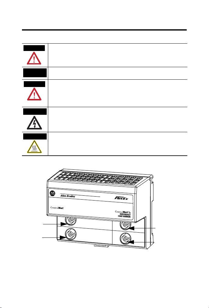
Component Identification
1 ControlNet Channel A In
2 ControlNet Channel B In
3 ControlNet Ex Channel B Out
4 ControlNet Ex Channel A Out
Publication
1797-5.35 - July 2004
Page 4
4 FLEX Ex Redundant ControlNet Barrier Module
.
x
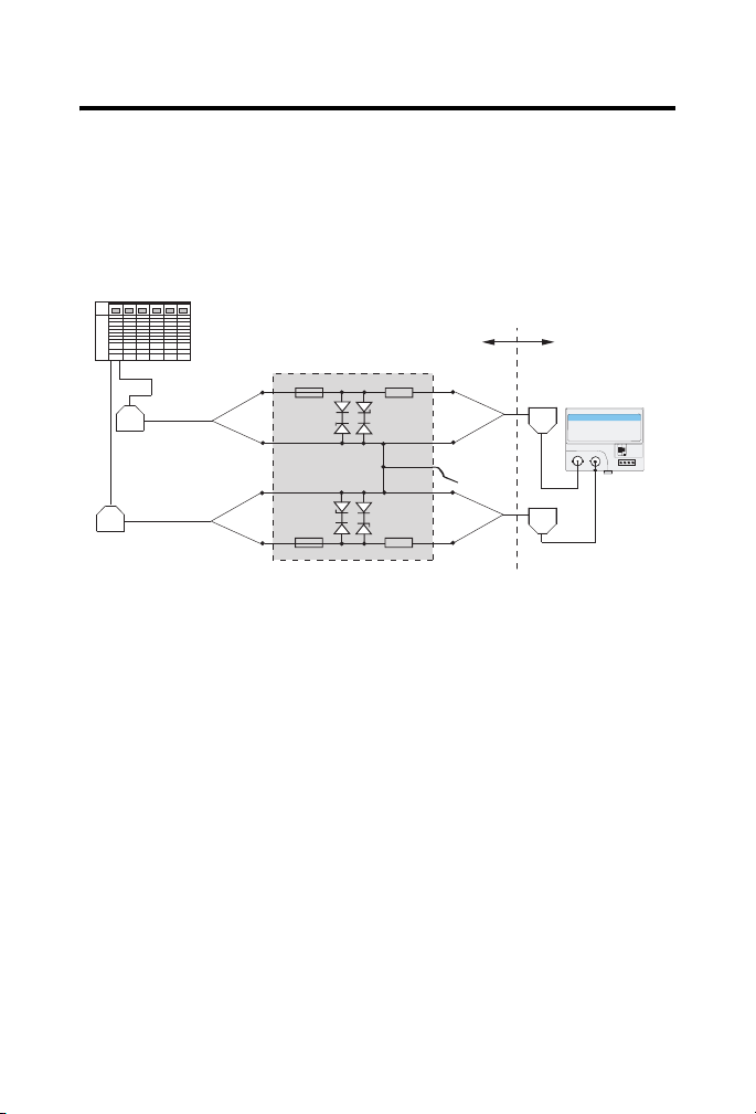
Product Features
• Provides for a direct connection to the ControlNet coax into
hazardous areas
• Can be mounted in a nonhazardous (safe) area
• Supports up to 10 adapters at 250 meters or 2 adapters at 500 meters
A functional illustration of the FLEX Ex Barrier Module is shown below.
Hazardous Area
ControlNet Ex TAP
(e.g., 1797-TPR)
.
.
ControlNet E
Adapter
ControlNet Ex
TAP
ControlNet A
ControlNet Ex TAP
(e.g., 1797-TPR)
ControlNet B
ControlNet Ex TAP
(e.g., 1797-TPR)
Safe Area
ControlNet barrier
PA
43464
Publication
1797-5.35 - July 2004
Page 5
FLEX Ex Redundant ControlNet Barrier Module 5
Mounting the Barrier on a DIN Rail Before Installing Modules
A
B
In
In
C
Channel A
Channel B
Out
Out
B
43477
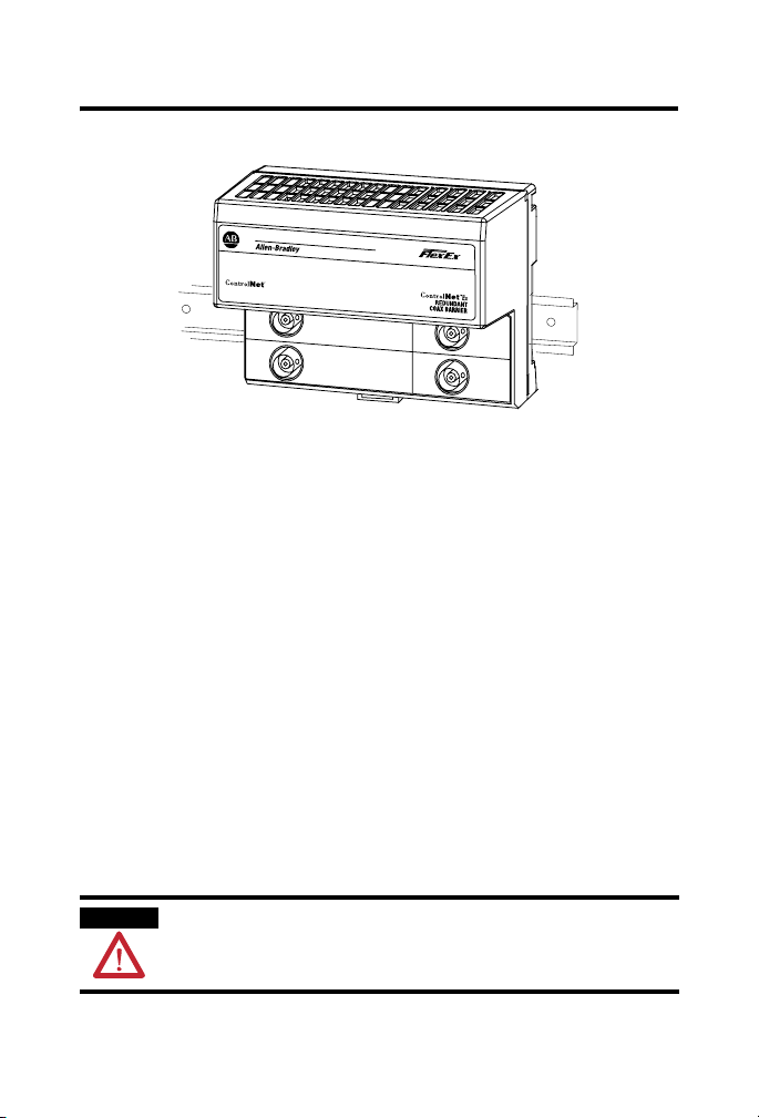
The 1797-BCNR module mounts on a DIN rail.
1. Position the ControlNet Ex barrier module (A) on a 35 x 7.5mm DIN
rail (B) (A-B pt. no. 199-DR1) at a slight angle.
2. Hook the lip on the rear of the barrier (A) onto the top of the DIN
rail (B), and rotate the module onto the rail.
3. Press the barrier module down onto the DIN rail until flush.
4. The locking tab (C) should snap into position and lock the barrier
module to the DIN rail.
5. If the barrier module does not snap into position, use a screwdriver or
similar device to move the locking tab down while pressing the barrier
module flush onto the DIN rail. Release the locking tab to lock the
module in place.
6. If necessary, push up on the locking tab to lock.
7. Make certain that you only connect the ControlNet Ex side of the
1797-BCNR to 1797 ControlNet taps with either a 1797-ACNR15 or
a 1797-TCAP attched.
WARNING
The 1797-BCNR cannot be used in an intrinsically safe
environment after the ControlNet Ex connections have been
exposed to non-intrinsically safe signals.
Publication
1797-5.35 - July 2004
Page 6

6 FLEX Ex Redundant ControlNet Barrier Module
Installation in Zone 2
This 1797-BCNR must not be exposed to the environment. This barrier
module has a protection factor of IP20. Mount the 1797-BCNR inside an
enclosure with a protection class IP54.
Installation in Zone 22
When the 1797-BCNR is installed in Zone 22, the following cabinets must be
used: IVK2-ISRPI-V16LC; IVK2-ISRPI-V8HYW; or IVK2-ISRPI-V8LC.
These cabinets can be purchased from:
Pepperl+Fuchs GmbH
Konigsberger Allee 85-87, D-68307
Mannheim, Germany
Attn: PA Sales Dept.
Kirsten Becker
Telephone +49 776 1298
www.pepperl-fuchs.com
The IS-RPI cabinets (type IVK2-ISRPI-V8LC, IVK2-ISRPI-V8HYW, or
IVK2-ISPRI-V16LC) ensures the basic protection for the intrinsically safe
apparatus of the IS-RPI system for use in Zone 22. It corresponds with
category 3D according to RL 94/9 EG and with the type label marked with
the following information:
Pepperl+Fuchs GmbH
68301 Mannheim
IVK2-ISRPI-V8LC (or IVK2-ISRPI-V8HYW or
IVK2-ISRPI-V16LC)
II 3D IP54 T 70°C
CE
Serial (manufacturing) number
Model Year
Publication
1797-5.35 - July 2004
Page 7
Electrostatic Charge
FLEX Ex Redundant ControlNet Barrier Module 7
ATTENTION
Preventing Electrostatic Discharge
This equipment is sensitive to electrostatic discharge, which
can cause internal damage and affect normal operation. Follow
these guidelines when you handle this equipment:
• Touch a grounded object to discharge potential static.
• Wear an approved grounding wriststrap.
• Do not touch connectors or pins on component boards.
• Do not touch circuit components inside the equipment.
• If available, use a static-safe workstation.
• When not in use, store the equipment in appropriate
static-safe packaging.
Protect the system against electrostatic charge. Post a sign near this barrier
module: Attention! Avoid electrostatic charge. For your convenience, a
sign which can be cut out is included at the end of this installation instruction.
European Community (EC) Directive Compliance
If this product has the CE mark it is approved for installation within the
European Community or EEA regions. It has been designed and tested to
meet the following directives.
These products are tested to meet the Council Directive 89/336/EEC
Electromagnetic Compatibility (EMC) as amended by 92/31/EC and
93/68/EEC, by applying the following standards:
• EN 61000-6-4:2001, Electromagnetic Compatibility (EMC) - Part 6-4:
Generic Standard for Industrial Environments (Class A)
• EN 61000-6-2:2001, Electromagnetic Compatibility (EMC) - Part 6-2:
Generic Standards - Immunity for Industrial Environments
• EN61326-1997 + A1-A2, Electrical Equipment For Measurement,
Control, and Laboratory Use - Industrial EMC Requirements
Publication
1797-5.35 - July 2004
Page 8

8 FLEX Ex Redundant ControlNet Barrier Module
ATEX Directive
These products are tested in conjunction with associated I/O modules to
meet the Council Directive 94/9/EC (ATEX) Equipment and Protective
Systems Intended for Use in Potentially Explosive Atmospheres by applying
the following standards:
• EN50014:1997 + A1-A2, Electrical Apparatus for Potentially
Explosive Atmospheres
• EN50020:1994, Electrical Apparatus for Potentially Explosive
Atmospheres - Intrinsic Safety “i”
• EN50021:1999, Electrical Apparatus for Potentially Explosive
Atmospheres - Non-Sparking “n”
UL, C-UL Compliance
If this product has the UL/C-UL mark, it has been designed, evaluated,
tested, and certified to meet the following relevant standards:
• UL 913, 1988, Intrinsically Safe Apparatus and Associated Apparatus
for Use in Class I, II, and III Division 1, Hazardous (Classified)
Locations
• UL 1203, Explosion-Proof and Dust-Ignition-Proof Electrical
Equipment for Use in Hazardous (Classified) Locations
• UL 2279, Electrical Equipment for Use in Class I, Zone 0, 1, and 2
Hazardous (Classified) Locations
• UL 508, Industrial Control Equipment
• CSA C22.2 No. 157-92, Intrinsically Safe and Non-Incendive
Equipment for Use in Hazardous Locations
• CSA C22.2 No. 30-M1986, Explosion-Proof Enclosures for Use in
Class I Hazardous Locations
• CSA-E79-0-95, Electrical Apparatus for Explosive Gas Atmospheres,
Part 0: General Requirements
• CSA-E79-11-95, Electrical Apparatus for Explosive Gas
Atmospheres, Part 11: Intrinsic Safety “i”
• CSA C22.2 No. 14-95, Industrial Control Equipment
Publication
1797-5.35 - July 2004
Page 9

FLEX Ex Redundant ControlNet Barrier Module 9
Inputs/Outputs
Do not apply any non-instrinsically safe signals to the FLEX Ex side of the
1797-BCNR.
When used as an associated apparatus according to EN50020, the European
directives and regulations must be followed.
1797-BCNR
ControlNet
IS
Wiring
E
In
A
In
Redundant cables
1. Connect the ControlNet Ex trunk cable to connector, terminal B
after removing the insulator boot.
Channel A
Channel B
D
Out
B
Out
C
30502-mdin
ControlNet Ex
43465
Publication
1797-5.35 - July 2004
Page 10

10 FLEX Ex Redundant ControlNet Barrier Module
2. Connect the redundant ControlNet Ex trunk cable to connector C
after removing the insulator boot.
IMPORTANT
Only remove the 1797-BCNR covers if the ControlNet Ex tap
drop cable is installed.
3. Connect the ControlNet trunk cable to terminal A.
4. Connect the redundant ControlNet trunk cable to terminal D.
5. Install a direct ground wire with a minimum diameter of 4mm2
between terminal E and the PA Ground (Equipotential System) in the
hazardous area where the ControlNet Ex coax cable is installed.
Do not connect terminal E or the DIN rail to a standard earth ground
connection in the safe area.
When using a 1797-BCNR, the total allowable length of a segment containing
standard RG-6 quad shield cable depends upon the number of nodes in your
segment. There is no minimum trunk-cable section length requirement. The
maximum allowable length of a segment which contains a 1797-BCNR is
500m. (1640 ft.) with two nodes connected (one node on each side of the
1797-BCNR).
Each additional node decreases the maximum length of the segment
according to the plot below. The maximum number of non-redundant media
nodes allowed on a segment is 21 with a maximum length of 250m (820 ft.).
Please note that the maximum number of redundant media nodes on a
segment is 11 with a maximum length of 250m (820ft.).
500
Publication
21 non-redundant
nodes or 11
redundant nodes
Segment Length (m)
250
Number of Nodes with One 1797-BCNR
1797-5.35 - July 2004
Page 11

FLEX Ex Redundant ControlNet Barrier Module 11
Mounting Dimensions
3.55
(9)
2.76
(7)
In
In
Channel A
Channel B
Out
Out
Inches
(Millimeters)
41413
3.94
(10)
Repair
The 1797-BCNR module is not field-repairable. Any attempt to open this
1797-BCNR module will void the warranty and the IS certification. If repair is
necessary, return the 1797-BCNR module to the manufacturer.
Specifications
1797-BCNR Specifications
Power Supply No power supply needed
Galvanic Isolation None
IS Module Type EEx [ib] IIC
ControlNet Ex System U
Non Ex ControlNet Un 5V
Bus Non-EX side ControlNet International Version 1.5
Bus Ex side Ex version of ControlNet International Version 1.5
7V
o
I
55mA @ 52KHz
o
P
negligible
o
Um 253 VAC
I not defined
P not defined
Publication
1797-5.35 - July 2004
Page 12

12 FLEX Ex Redundant ControlNet Barrier Module
1797-BCNR Specifications
Transmission Rate 5 Mbit/s
Transmission Attenuation -7.84dB
Weight Approximately 200g
Dimensions 3.94 in.(w) x 3.55 in.(d) x 2.76 in.(h)
10cm(w) x 9cm(d) x 7 cm(h)
Operating Temperature IEC 60068-2-1 (Test Ad, Operating Cold),
Storage Temperature IEC 60068-2-1 (Test Ab, Un-packaged Non-operating Cold),
Relative Humidity IEC 60068-2-30 (Test Db, Un-packaged Non-operating
Shock IEC60068-2-27 (Test Ea, Unpackaged shock):
Vibration IEC60068-2-6 (Test Fc, Operating):
Emissions CISPR 11:
ESD Immunity IEC 61000-4-2:
Radiated RF Immunity IEC 61000-4-3:
EFT/B Immunity IEC 61000-4-4:
Surge Transient Immunity IEC 61000-4-5:
IEC 60068-2-2 (Test Bd, Operating Dry Heat),
IEC 60068-2-14 (Test Nb, Operating Thermal Shock):
-20 to 70oC (-4 to 158oF)
IEC 60068-2-2 (Test Bb, Un-packaged Non-operating Dry
Heat),
IEC 60068-2-14 (Test Na, Un-packaged Non-operating
Thermal Shock):
-20 to 100oC (-4 to 212oF)
Damp Heat):
5 to 95% non-condensing
Operating 30g
Non-operating 50g
5g @ 10-500Hz
Group 1, Class A
8kV indirect discharges
10V/m with 1kHz sine-wave 80%AM from 30MHz to
2000MHz
10V/m with 200Hz 50% Pulse 100%AM at 900Mhz
±2kV at 5kHz on communications ports
±2kV line-earth(CM) on shielded ports
Publication
1797-5.35 - July 2004
Page 13

FLEX Ex Redundant ControlNet Barrier Module 13
1797-BCNR Specifications
Conducted RF Immunity IEC 61000-4-6:
10Vrms with 1kHz sine-wave 80%AM from 150kHz to
80MHz
Enclosure Type Rating None (open-style)
Certifications1
(When Product is Marked)
1. See the Product Certification link at www.ab.com for Declarations of Conformity,
Certificates, and other certification details.
CENELEC DMT 99 ATEX EO65 X
II (2) G[EEx ib] IIC
II 3G EEx nA IIC T4 X
CE European Union 89/336/EEC EMC
Directive, compliant with:
EN 61326; Meas./Control/Lab.,
Industrial Requirements
EN 61000-6-4; Industrial
Emissions
EN 61000-6-2; Industrial Immunity
cULus Provides intrinsically safe outputs for use in
Class I, Division 1, Groups A, B, C, and D;
Class II, Groups E, F, and G; Class III;
Class 1, Zone 1 Group IIC
C-Tick Australian Radiocommunications
Act, compliant with:
AS/NZS CISPR 11; Industrial
Emissions
EEx European Union 94/9/EEC ATEX
Directive, compliant with:
EN 50014; Potentially Explosive
Atmospheres General
Requirements
EN 50020; Potentially Explosive
Atmospheres, Protection “i”
EN 50021; Potentially Explosive Atmospheres,
Protection "n" (Zone 2)
Publication
1797-5.35 - July 2004
Page 14

14 FLEX Ex Redundant ControlNet Barrier Module
Describing the ControlNet Ex System Diagrams
A maximum of 48 ControlNet ExTM nodes may be connected together by
250m of coax cable and 48 taps. The distance increases to 1000m when you
use only 2 taps. See the table below for more information.
The fiber media of the 1797-RPFM can be installed in a hazardous location
(Zone 0, 1 or 2; Class I, Zones 0, 1, and 2; Class I, Division 1 and 2; Class II,
Division 1 and 2; Class III, Division 1 and 2) to connect two 1797-RPFM
modules or they can be installed through different locations into the
non-hazardous location to connect the 1797-RPFM with any approved
associated apparatus.
All cables and fiber media that are not light blue must be marked as IS using
the 1797-EXMK marking kit or other locally approved IS identification
and/or segregation method.
During the installation of the ControlNet Ex system, all metallic parts must be
isolated to prevent an earth connection (high voltage withstanding of isolating
material must be > 500V ac).
System
Diagram Name
1797-RPA 1797-RPA ControlNet Ex
1797-RPFM 1797-RPFM ControlNet Ex Fiber
1797-ACNR15 1797-ACNR15 Redundant Media
Catalog
Number
Catalog Name Description
Represents one ControlNet Ex
Modular Repeater
Adapter
Repeater Module,
Medium Distance
ControlNet Ex
Adapter
node and must be connected
to a coax trunk cable by
1797-TPx
Allows connection of a
maximum of two devices per
1797-RPA and is powered
directly by 1797-RPA
Represents one ControlNet Ex
node and must be connected
to a coax trunk cable by
1797-TPx -each one with two
redundant output channels
that are connected to different
ControlNet Ex networks (coax
cables and 1797-TPx)
Publication
1797-5.35 - July 2004
Page 15

FLEX Ex Redundant ControlNet Barrier Module 15
System
Diagram Name
Catalog
Number
Catalog Name Description
1797-BCNR 1797-BCNR ControlNet Ex
Redundant Media
Adapter
CNet Ex Tap Trm 1797-TCAP ControlNet Ex Tap
(Dummy) Terminator
ControlNet Ex
Tap
1797-TPx ControlNet Ex Coax
Tap
CNet Ex Trk Trm 1797-XT ControlNet Ex Trunk
Ter mi na to r
Coax Trunk Cable 1797-RG6 Quad-Shield, RG-6
75Ω Coax Trunk
Cable
None None Standard Coax Trunk
Cable BNC Couplers
Allows connection between a
ControlNet system and a
ControlNet Ex system
Represents one ControlNet Ex
node and is a simple capacitor
(56pF) with a coax connector
Four types of connections
available: S (straight t-tap), R
(right angle t-tap), YS (straight
y-tap), and YR (right angle
y-tap) - a maximum of 48 taps
can be connected together by
coax trunk cable
Simple resistor (75Ω) with
coax connector that must be
on each end of the ControlNet
Ex coax trunk for termination
Maximum (functional) length
between 2 1797-TPx is 3280ft
(1000m) - each 1797-TPx
reduces the (functional) coax
cable length by 53.4ft (16.3m)
Different standard cable
couplers, 90
o
, 180o, etc.
Publication
1797-5.35 - July 2004
Page 16

16 FLEX Ex Redundant ControlNet Barrier Module
Certified Equivalent ControlNet Ex System Diagram Items
You may use these items as equivalents for the items shown on the system
diagram.
System Diagram Name Catalog Number Source
1797-RPA 1797-RPA Allen-Bradley
1797-RPFM 1797-RPFM Allen-Bradley
1797-ACNR15 1797-ACNR15 Allen-Bradley
Coax Trunk Cable
1
ControlNet Ex Tap 1797-TPx Allen-Bradley
CNet Ex Trk Trm 1797-XT Allen-Bradley
CNet Ex Tap Trm 1797-TCAP Allen-Bradley
1 In addition to these cable types, the following specification can be followed to allow additional
types:
Cable Impedance = 75Ω + 3Ω
Cable Capacitance = <6nF per 100m
Cable Resistance = >9.08Ω per 100m
Cable Attenuation 0.2MHz > 0.93dB/100m 5MHz > 1.39dB/100m
(-20 to +70oC) 0.5MHz > 0.95dB/100m 10MHz > 1.86dB/100m
2 Belden Wire & Cable 1189A may be used, but with functional loss of communication distance
and/or nodes.
1797-RG6 Allen-Bradley
3092A
2
Belden Wire & Cable Co.
3092A with blue jacket Belden Wire & Cable Co.
1MHz > 1.07dB/100m 20MHz > 2.73dB/100m
2MHz > 1.16dB/100m 50MHz > 4.33dB/100m
Publication
1797-5.35 - July 2004
Page 17

FLEX Ex Redundant ControlNet Barrier Module 17
Certification Specific ControlNet Ex System Diagrams
The following pages include certification specific ControlNet Ex system
diagrams and notes pertaining to these diagrams. Select either CENELEC,
UL, C-UL, or FM and follow the requirements of that diagram as you
configure and install your system.
CENELEC Installation Label
A label with this system marking must be attached near the main components
of the system. If the system is installed in a cabinet, this label must be fixed
inside the cabinet.
Allen-Bradley
1 Allen-Bradley Dr.
Mayfield Hts., OH USA
ControlNet Ex System
DMT 99 ATEX E 065 X
II (1) 2G SYST EEx ia/ib IIB/C T4
-200C <= Ambient Temperature <= +700C
Attention!
Avoid electrostatic charging!
0102
CENELEC Information
The isolator type 1797-BCNR/* is an associated apparatus according to
50020. If the isolator is connected to intrinsically safe circuits the
EN
applicable national local construction, installation and operating regulations
must be heeded (for example, Germany DIN EN 50020, DIN VDE 0165).
Publication
1797-5.35 - July 2004
Page 18

18 FLEX Ex Redundant ControlNet Barrier Module
CENELEC C
N
H
d
L
i
System Diagram
ontrolNet Ex
Flexbus
Uo=5.4V,
Io=400mA,
Po=2.16W,
Co=65µF,
Lo=10µH
Ii=1A,
Ui=9.5V,
Power Supply
.
Node 4... 48
1797-ACNR15/* or
RSD-GW-Ex2.CN
.
1797-ACNR15/* or RSD-GW-Ex2.CN
Node 3
The ControlNet Ex System is an intrinsically safe system according to EN 50039. When installing the
system, the certificate of conformity and the national installation regulations must be heeded. The
components of the ControlNet Ex system and the interconnections are shown on the installation
drawing (A-B Pub. 1797-6.5.6).
Protect the system against electrostatic charge. Post a sign near the main components of the system:
Attention! Avoid electrost atic charge
.
Ch1
.
1797-RPFM/* or
RSD-FC-Ex2.CN 3km
.
Ch0
fiber
.
.
Uo=5.4V,
Io=160mA,
.
Flexbus
Uo=5.4V,
Io=400mA,
1
.
ChB
ChA
Uo=5.4V,
Io=160mA,
Po=2.16W,
Co=65µF,
Lo=10µH
Ii=1A,
Ui=9.5V,
Power Supply
.
ChB
Uo=5.4V,
Io=160mA,
ChA
>500kHz
Uo=5.4V,
Io=160mA,
F
fiber
Ch1
fiber
CNet Ex
120nF,
Ci<
Li=negligible
>500kHz
-3
F
>500kHz
-3
F
120nF,
Ci<
Li=negligible
>500kHz
-3
F
-3
coax trunk cable
Cable type 1189A, 3092A, or
1W
Li negl.
Ci negl.
75 Ohm
trk trm
tap
ControlNet Ex
coax trunk cable
tap
0.95dB/100m 10MHz > 1.86dB/100m
1.07dB/100m 20MHz > 2.73dB/100m
1.16dB/100m 50MHz > 4.33dB/100m
C) 0.2MHz > 0.93dB/100m 5MHz > 1.39dB/100m
o
5.94nF per 100m
ControlNet Ex
0.5MHz >
Cable Resistance >9.08 Ohm per 100m
Cable Attenuation (-20 to +7 0
1MHz >
*RG6-CNet is defined as:Cable Impedance = 75 Ohm + or - 3 Ohm
3092A Blue from manufacturer
Belden Wire or type RG6-CN et*
2MHz >
Cable Capacitance <
C.
o
tap
ControlNet Ex
.
1797-RPFM/* or
RSD-FC-Ex2.CN 3km
Zone 1
.
Hazardous Area
1797-RPFM/* or
RSD-FC-Ex2.CN 3km
Node 2
.
Ui=9.5V,
.
>500kHz Power Supply
-3
Uo=5.4V,
Io=201mA,
F
Ch0
fiber
120nF,
Ii=1A,
Ci<
Li=negligible
ControlNet Ex tap
PA
(Euipotential
bonding)
CNet Ex
The Coax Trunk Cable is permitted to have a maximum length of
1,000m with only 2 connected ControlNet Ex Taps dropping to only
250m with the maximum allowed connected ControlNet Ex Taps of
48.
Near the main components of the system a plate with the system marking must
be attached. If the system is installed in a cabinet, the plate must be fixed on the
inside of the cabinet door.
The ambient temperature range of the ControlNet Ex system is -20 to +70
Li < 1100uH
Ci < 60pF
Li < 560nH
trk trm
68pF
tap trm
Li negl.
CNet Ex
Ci <
Li < 1100uH
Node 1
on
.
ocat
RS-FB-Ex2.CN
1797-BCNR or
ous
azar
(Safe Area)
on
Publication
1797-5.35 - July 2004
.
(i.e., HFBR 1312 from
.
2
CNet
For the transmittal between the safe area
and the hazardous area only optical
glass-fibers are permitted. The diameter of
a single glass-fiber must be >6um.
The power density of the transmitter diode
must be <5mW/mm
Hewlett-Packard manufacturer).
Zone 0
Hazardous Area
30670-Mp
Page 19

FLEX Ex Redundant ControlNet Barrier Module 19
UL, C-UL ControlNet Ex System Diagram
Class II Division 1 Groups E, F, G
Class I, Zone 1, Groups IIC, IIB, IIA
Hazardous (Classified) Location
Class I Division 1 and 2, Groups A, B, C, D
1797-RPFM 1797-RPFM
Node 2
1797-RPA
1
)
i
, L
i
C
max
, I
max
Any IS device with entity
concept parameters
(V
6 8
3
Class III
Node 4 ... 48
1797-ACNR15
)
i
, L
i
C
max
, I
max
Any IS device with entity
concept parameters
(V
Node 3
1797-ACNR15
.
Ch1
.
Ch0
.
.
.
Ch1
.
.
Ch0
.
120nF, Li=0
Power Supply
Vmax=9.5V, Imax=1A,
.
Ci<
IS ground
7
Power Supply
Vmax=9.5V,
Imax=1A,
Ci<120nF,
appropriate for connection
to associated apparatus
with entity concept
parameters listed in Table 2.
Maximum devices=8.
.
1
2
.
9
ChBChA
To any approved device or
associated apparatus
.
appropriate for connection
to associated apparatus
with entity concept
parameters listed in Table 2.
Maximum devices=8.
.
1
.
.
with entity concept
7
120nF,
Power Supply
Vmax=9.5V,
Imax=1A,
Ci<
Li=0
2
9
ChB
To any approved device or
associated apparatus
with entity concept
ChA
54
fiber optic cable
2
1
<1A
sc
<9.5V and I
oc
To any IS device or
associated apparatus
with entity eoncept
parameters of
V
clamp
Li=0
1
=1A
sc
=9.5V and I
oc
parameters of
V
6
CNet Ex
trk trm
tap
ControlNet Ex
6
2
Zone 1 or 2, IIC
Class I, Zones 1 and 2, Groups IIC, IIB, IIA
Class I Division 1 and 2, Groups A, B, C, D
2
coax trunk cable
Class III, Division 1 and 2
Class II, Division 1 and 2, Groups E, F, G
coax trunk cable
1
=1A
sc
tap
ControlNet Ex
=9.5V and I
oc
parameters of
V
tap
ControlNet Ex
2
tap
Node 1
ControlNet Ex
Hazardous (Classified) Location
C.
o
CNet Ex
tap trm
The ambient temperature range of the ControlNet
Ex system is -20 to +70
1797-BCNR or
.
RS-FB-Ex2.CN
929
ChB
.
.
CNet
ChB
ChA
1786-RPFM
2
or
is <5mW/mm
any associated
emitting diode output
apparatus where the light
Publication
Location
Groups A, B, C, D
Groups IIC, IIB, IIA
Class I Division 1 and 2,
Class I, Zones 0, 1 and 2,
Hazardous (Classified)
1797-5.35 - July 2004
Groups E, F, G
Class II, Division 1 and 2,
Class III, Division 1 and 2
30670-M
Page 20

20 FLEX Ex Redundant ControlNet Barrier Module
UL, C-UL ControlNet Ex System Diagram Notes
The entity concept allows interconnection of intrinsically safe apparatus
with associated apparatus not specifically examined in combination as a
system when the approved values of V
apparatus are less than or equal to V
apparatus and the approved values of C
are greater than C
+ C
i
and Li + L
cable
apparatus.
Wiring methods must be in accordance with the National Electric Code,
ANSI/NFPA 70, Article 504 and 505 or the Canadian Electric Code CSA
C22.1, Part 1, Appendix F. For additional information refer to ANSI/ISA
RP12.6.
WARNING: Substitution of components may impair intrinsic safety.
AVERTISSEMENT: La substitution de composant peut compromettre la
securite intrinseque.
If fiber optic cable is provided with a metal shield, it must be connected
to a dedicated intrinsic safety ground in the non-hazardous location and tied
back in the hazardous location or be connected to a ground in the hazardous
location and tied back in the non-hazardous location.
The glass fiber must have a minimum diameter of 6µm.
➅ For Class II, Division 1, Groups E, F, G and Class III, modules must be
installed in a UL listed Type 4, 4X, 6, 6P, 9, 12, or 12K enclosure. (The power
supply does not need to be put into an additional enclosure. Refer to the
power supply section of this manual for more information.)
and Isc or Vt and It of the associated
oc
and I
max
cable
of the intrinsically safe
max
and La of the associated apparatus
a
respectively for the intrinsically safe
➆ Any combination of up to eight FLEX Ex I/O modules may be
connected. This includes using 1794-CE3, 1797-CE3, 1794-CE1, and
1797-CE1 cables.
➇ The ambient temperature range (T
➈ Channel B is intended for a redundant connection and is identical to the
) for this system is -20oC to 70oC.
amb
channel A configuration.
Publication
1797-5.35 - July 2004
Page 21

FLEX Ex Redundant ControlNet Barrier Module 21
Application
The 1797-BCNR/* functions as a barrier for signals between ControlNet and
ControlNet Ex. The 1797-BCNR must be installed in safe, Zone 2 or
Division 2 areas.
Isolator Boot for ControlNet Ex
The isolator boot for the ControlNet Ex 1797-BCNR connectors can only be
removed when a ControlNet Ex trunk cable is connected. Any unused
connector on the ControlNet side must have its insulator boot installed. The
ControlNet Ex connection must not be connected to any signals which
exceed the intrinsically safe values of the ControlNet Ex network.
Attention: Avoid electrostatic charge.
IMPORTANT
For detailed certification information, refer to the FLEX
Ex System Certification Reference Manual, publication
1797-6.5.6.
ControlNet is a trademark of ControlNet International.
FLEX Ex and ControlNet Ex are trademarks of Rockwell Automation.
Publication
1797-5.35 - July 2004
Page 22

22 FLEX Ex Redundant ControlNet Barrier Module
Publication
1797-5.35 - July 2004
Page 23

FLEX Ex Redundant ControlNet Barrier Module 23
Publication
1797-5.35 - July 2004
Page 24

Publication 1797-5.35 - July 2004 PN 957899-25
Supersedes Publication 1797-5.35 - December 2003 Copyright © 2004 Rockwell Automation, Inc. All rights reserved. Printed in the U.S.A.
 Loading...