

Page 1

Installation Instructions
ControlNet Ex Redundant Media Adapter
Catalog Number 1797-ACNR15
Contents
For Information About See Page
Important User Information 2
Module Installation 5
Installation in Zone 1 8
Installation in Zone 22 8
Electrostatic Charge 9
Inputs/Outputs 11
ControlNet Ex Adapter Operation 12
FLEX Ex Output Module Operation 13
Wire the Adapter 14
Description of the ControlNet Ex System Diagrams 16
Certification Specific ControlNet Ex System Diagrams 19
CENELEC Installation Label 19
CENELEC ControlNet Ex System Diagram 20
UL, C-UL ControlNet Ex System Diagram 21
FM ControlNet Ex System Diagram 23
Indicators 25
Comm, Module, and Power Status Indicators 25
Dimensions for Mounting the Adapter 27
About the Mounting Kit 27
Repair 28
Specifications 28
Ferrite Beads 31
Publication 1797-5.14 - March 2010
Page 2
2 ControlNet Ex Redundant Media Adapter
WARNING
IMPORTANT
ATTENTION
SHOCK HAZARD
BURN HAZARD
Important User Information
Solid state equipment has operational characteristics differing from those of
electromechanical equipment. Safety Guidelines for the Application, Installation and
Maintenance of Solid State Controls (Publication SGI-1.1 available from your local Rockwell
Automation sales office or online at
describes some important differences between solid state equipment and hard-wired
electromechanical devices. Because of this difference, and also because of the wide variety
of uses for solid state equipment, all persons responsible for applying this equipment must
satisfy themselves that each intended application of this equipment is acceptable.
In no event will Rockwell Automation, Inc. be responsible or liable for indirect or
consequential damages resulting from the use or application of this equipment.
The examples and diagrams in this manual are included solely for illustrative purposes.
Because of the many variables and requirements associated with any particular installation,
Rockwell Automation, Inc. cannot assume responsibility or liability for actual use based on
the examples and diagrams.
No patent liability is assumed by Rockwell Automation, Inc. with respect to use of
information, circuits, equipment, or software described in this manual.
Reproduction of the contents of this manual, in whole or in part, without written permission
of Rockwell Automation, Inc., is prohibited.
Throughout this manual we use notes to make you aware of safety considerations.
Identifies information about practices or circumstances that can cause an explosion in a
hazardous environment, which may lead to personal injury or death, property damage, or
economic loss.
Identifies information that is critical for successful application and understanding of the
product.
Identifies information about practices or circumstances that can lead to personal injury or
death, property damage, or economic loss. Attentions help you: identify a hazard, avoid a
hazard, and recognize the consequence
http://www.literature.rockwellautomation.com)
Publication
Labels may be located on or inside the equipment to alert people that dangerous voltage
may be present.
Labels may be located on or inside the equipment to alert people that surfaces may be
dangerous temperatures.
1797-5.14 - March 2010
Page 3
ControlNet Ex Redundant Media Adapter 3
ATTENTION
Environment and Enclosure
This equipment is considered Group 1, Class A industrial
equipment according to IEC/CISPR Publication 11. Without
appropriate precautions, there may be potential difficulties
ensuring electromagnetic compatibility in other environments
due to conducted as well as radiated disturbance.
This equipment is supplied as open-type equipment. It must be
mounted within an enclosure that is suitably designed for those
specific environmental conditions that will be present and
appropriately designed to prevent personal injury resulting from
accessibility to live parts. The interior of the enclosure must be
accessible only by the use of a tool. Subsequent sections of this
publication may contain additional information regarding
specific enclosure type ratings that are required to comply with
certain product safety certifications.
Publication
1797-5.14 - March 2010
Page 4
4 ControlNet Ex Redundant Media Adapter
PWR
1797-ACNR15
3
2
41408
1
2
3
4
5
6
7
8
Do not remove unless
connecting a terminal
base unit.
9
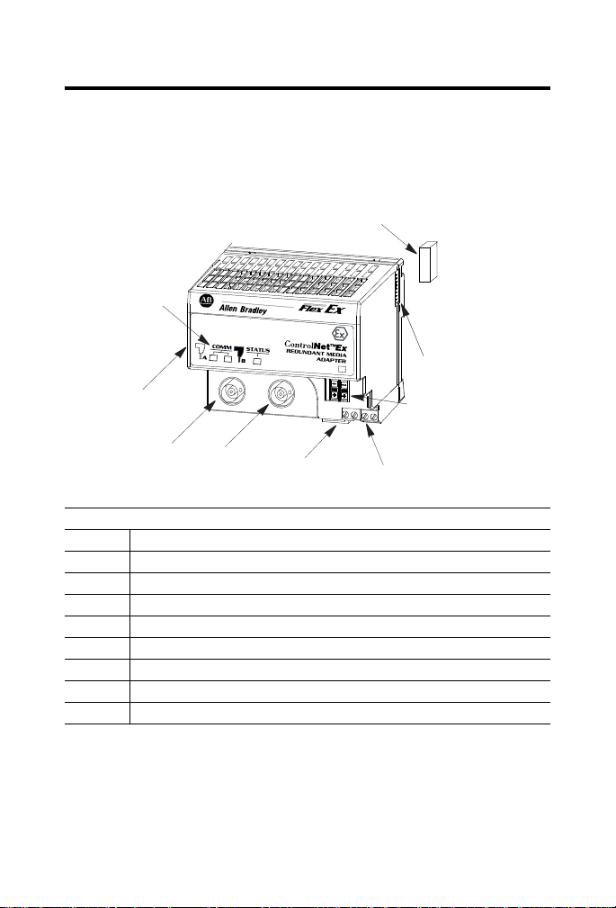
About the ControlNet Ex Adapter
Use the redundant media adapter to connect FLEX Ex modules to the
ControlNet Ex network.
Component Identification
1 Indicators
2 Label
3 ControlNet Ex tap drop BNC connector channel A with insulator boot
4 ControlNet Ex tap drop BNC connector channel B with insulator boot
5 Module locking tab
6 Removable power connectors
7 Backplane connector
8 Backplane connector cover
9 Node address push switch
Publication
1797-5.14 - March 2010
Page 5
ControlNet Ex Redundant Media Adapter 5
ATTENTION
41307
P
W
R
PWR
1797-ACNR15
3
2
32
A
B
C
41409
Module Installation
This adapter must not be exposed to the environment. Provide a suitable
metal enclosure. This adapter has a protection factor of IP20.
This product is grounded through the DIN rail to the dedicated
intrinsic safety ground. Use zinc-plated yellow-chromate steel
DIN rail to assure proper grounding. The use of other DIN rail
materials (such as aluminum or plastic) that can corrode, oxidize,
or are poor conductors, can result in improper or intermittent
grounding.
Make certain that you only connect ControlNet Ex adapters to other
intrinsically safe system modules to maintain the integrity of the
intrinsically-safe backplane.
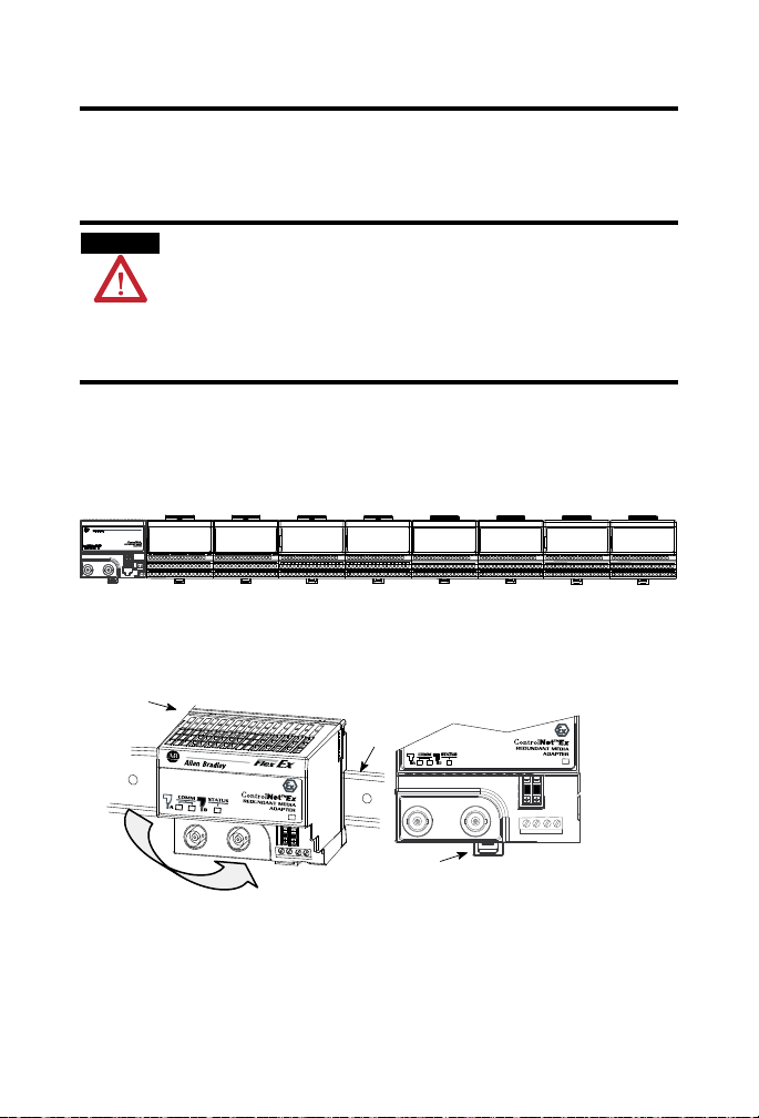
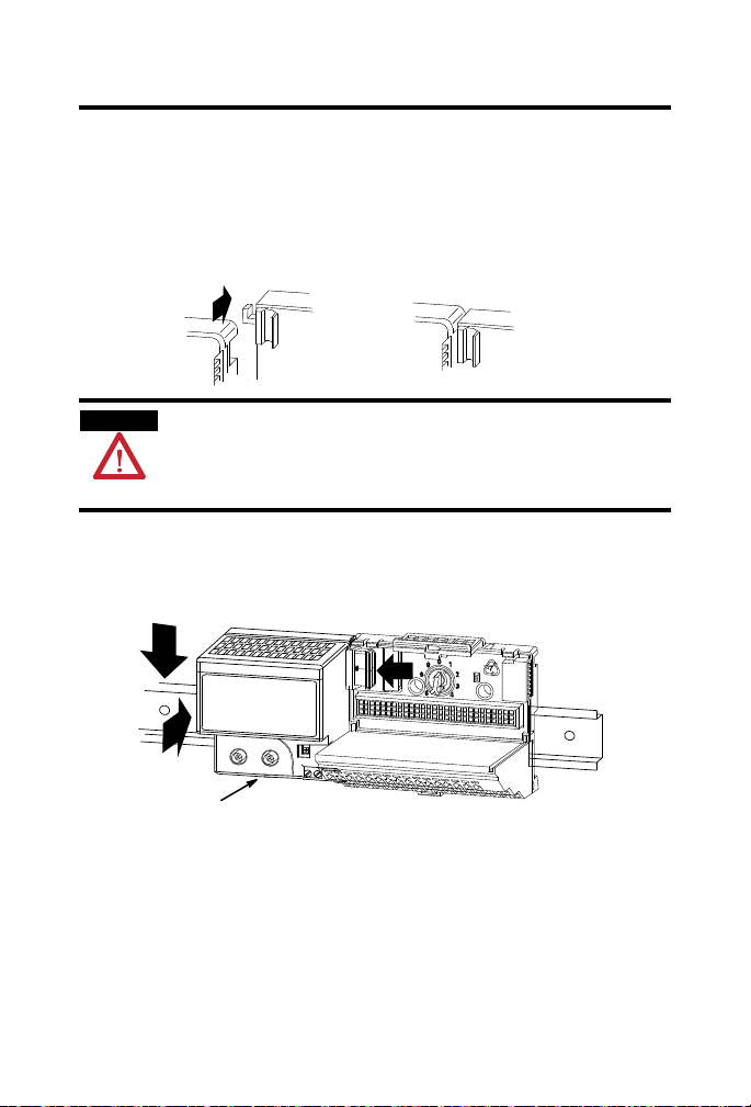
Install the Adapter
1. Position the ControlNet Ex adapter module (A) on a 35 x 7.5 mm
DIN rail (B) (A-B pt. no. 199-DR1) at a slight angle.
Publication
1797-5.14 - March 2010
Page 6
6 ControlNet Ex Redundant Media Adapter
ATTENTION
2. Hook the lip on the rear of the adapter (A) onto the top of the DIN
rail (B), and rotate the module onto the rail.
3. Press the adapter module down onto the DIN rail until flush.
4. The locking tab (C) should snap into position and lock the adapter
module to the DIN rail.
5. If the adapter does not snap into position, use a screwdriver or similar
device to move the locking tab down while pressing the adapter
module flush onto the DIN rail. Release the locking tab to lock the
module in place.
6. If necessary, push up on the locking tab to lock.
7. Connect the adapter wiring as shown under Wiring later in this
document.
Mount (or Replace) the Adapter on an Existing System
1. Disconnect the BNC connectors from the front of the ControlNet Ex
adapter.
2. Remove the front power plug from the ControlNet Ex adapter.
3. Remove the I/O module from the terminal base unit that is to the
immediate right of the ControlNet Ex adapter.
4. Push the flexbus connector toward the right side of the terminal base
to unplug the backplane connection.
Make certain that the flexbus connector is completely clear of
the adapter. The slide must be completely to the right and the
raised spot on the slide visible.
5. Release the locking tab and remove the adapter.
6. Remove the backplane connector cover from the adapter.
Publication
1797-5.14 - March 2010
Page 7
ControlNet Ex Redundant Media Adapter 7
ATTENTION
40564
41410
Push down and in at the
same time to lock the
adapter to the DIN rail.
When the adapter is locked onto the DIN
rail, gently push the flexbus connector into
the adapter to complete the backplane.
C
7. Before installing the new adapter, notice the notch on the right rear of
the adapter.
This notch accepts the hook on the terminal base unit. The notch is
open at the bottom. The hook and adjacent connection point keep the
terminal base and adapter tight together, reducing the possibility of a
break in communication over the backplane.
Make certain that the hook on the terminal base is properly
hooked into the adapter. Failure to lock the hook into the
adjacent base/adapter can result in loss of communication on
the backplane.
8. Complete the adapter mounting as shown below.
10. Push up on the locking tab to lock, if necessary.
11. Reinstall the I/O module into the terminal base unit.
12. Make sure the last terminal base has its right-side flexbus connector
9. If the adapter module does not lock in place, use a screwdriver or
similar device to move the locking tab (C) down while pressing the
adapter module flush onto the DIN rail.
Then release the locking tab to lock the adapter module in place.
cover in place.
Publication
1797-5.14 - March 2010
Page 8
8 ControlNet Ex Redundant Media Adapter
WARNING
Installation in Zone 1
The adapter must not be exposed to the environment. Provide a suitable
metal enclosure. The adapter has a protection factor of IP20.
The adapter cannot be used in an intrinsically safe environment
after they have been exposed to nonintrinsically safe signals.
Installation in Zone 22
When the adapter is installed in Zone 22, the following cabinets must be used:
IVK-ISRPI-V16LC; IVK-ISRPI-V8HYW; or IVK-ISRPI-V8LC. These
cabinets can be purchased from:
Pepperl+Fuchs GmbH
Lilienthalstrasse 200
68307 Mannheim, Germany
Attn: PA Sales Dept.
Kirsten Becker
Telephone +49 776 1298
www.pepperl-fuchs.com
The IS-RPI cabinets (type IVK2-ISRPI-V8LC, IVK2-ISRPI-V8HYW, or
IVK2-ISPRI-V16LC) ensures the basic protection for the intrinsically safe
apparatus of the Flex Ex system for use in Zone 22. It corresponds with
category 3D according to RL 94/9 EG and with the type label marked with
the following information:
Pepperl+Fuchs GmbH
68307 Mannheim
IVK2-ISRPI-V8LC (or IVK2-ISRPI-V8HYW or
IVK2-ISRPI-V16LC)
II 3 D Ex tD A22 IP54 T70 °C X
CE
Serial (manufacturing) number
Model
Publication
1797-5.14 - March 2010
Page 9

ControlNet Ex Redundant Media Adapter 9
Electrostatic Charge
Protect the system against electrostatic charge. Post a sign near this adapter:
WARNING Avoid electrostatic charging.
ADVERTÊNCIA! PREVENIR CONTRA O ACÚMULO DE CARGA
ELETROSTÁTICA.
For your convenience, a sign that can be cut out is included in this installation
instruction.
European Community (EC) Directive Compliance
If this product has the CE mark it is approved for installation within the
European Community or EEA regions. It has been designed and tested to
meet the following directives.
EMC Directive
These products are tested to meet the Council Directive 2004/108/EC by
applying the following standards:
• EN 61000-6-4:2007, Electromagnetic Compatibility (EMC) - Part 6-4:
Generic Standard for Industrial Environments (Class A)
• EN 61000-6-2:2005, Electromagnetic Compatibility (EMC) - Part 6-2:
Generic Standards - Immunity for Industrial Environments
• EN61326-1:2006 (Industrial), Electrical Equipment For
Measurement, Control, and Laboratory Use - Industrial EMC
Requirements
Publication
1797-5.14 - March 2010
Page 10

10 ControlNet Ex Redundant Media Adapter
ATEX Directive
These products are tested in conjunction with associated I/O modules to
meet the Council Directive 94/9/EC (ATEX) Equipment and Protective
Systems Intended for Use in Potentially Explosive Atmospheres by applying
the following standards:
• EN60079-11:2007, Explosive atmospheres - Part 11 : equipment
protection by intrinsic safety "i"
• EN60079-0:2006, Electrical apparatus for explosive gas atmospheres Part 0 : general requirements
• EN 60079-26 : 2004, Electrical apparatus for explosive gas
atmospheres - Part 26 : construction, test and marking of Group II
Category 1 G electrical apparatus
• EN61241-0 : 2006, Electrical apparatus for use in the presence of
combustible dust - Part 0: General requirements
• EN61241-11:2006, Electrical apparatus for use in the presence of
combustible dust – Part 11: Protection by intrinsic safety 'iD'
UL, C-UL Compliance
If this product has the UL/C-UL mark, it has been designed, evaluated,
tested, and certified to meet the following relevant standards:
• UL 913, 1988, Intrinsically Safe Apparatus and Associated Apparatus
for Use in Class I, II, and III Division 1, Hazardous (Classified)
Locations
• UL 1203, Explosion-Proof and Dust-Ignition-Proof Electrical
Equipment for Use in Hazardous (Classified) Locations
• UL 2279, Electrical Equipment for Use in Class I, Zone 0, 1, and 2
Hazardous (Classified) Locations
• UL 61010, UL Standard for Safety Electrical Equipment For
Measurement, Control, and Laboratory Use; Part 1: General
Requirements
• CSA C22.2 No. 157-92, Intrinsically Safe and Non-Incendive
Equipment for Use in Hazardous Locations
• CSA C22.2 No. 30-M1986, Explosion-Proof Enclosures for Use in
Class I Hazardous Locations
Publication
1797-5.14 - March 2010
Page 11

ControlNet Ex Redundant Media Adapter 11
40055
Power
Supply
+V
-V
Channel A
Channel B
Network
uC uC
Dual
Port
RAM
Bus
Flexbus
• CSA-E79-0-95, Electrical Apparatus for Explosive Gas Atmospheres,
Part 0: General Requirements
• CSA-E79-11-95, Electrical Apparatus for Explosive Gas
Atmospheres, Part 11: Intrinsic Safety “i”
• CSA C22.2 No. 14-95, Industrial Control Equipment
FM Compliance
If this product has the FM mark, it has been designed, evaluated, tested, and
certified to meet the following standards:
• FM C1. No.3600:1998, Electrical Equipment for Use in Hazardous
(Classified) Locations General Requirements
• FM C1. No.3610:1999, Intrinsically Safe Apparatus and Associated
Apparatus for Use in Class I, II, III Division 1 Hazardous (Classified)
Locations
• FM C1. No.3615:1989, Explosionproof Electrical Equipment General
Requirements
• FM C1. No.3810:1989, 1995, Electrical and Electronic Test,
Measuring and Process Control Equipment
• ANSI/NEMA 250, 1991, Enclosures for Electrical Equipment
Inputs/Outputs
Do not apply any nonintrinsically safe signals to the adapter.
When using as an intrinsically safe electrical apparatus according to EN
60079-11, the European directives and regulations must be followed.
Publication
1797-5.14 - March 2010
Page 12

12 ControlNet Ex Redundant Media Adapter
ControlNet Ex Adapter Operation
The ControlNet Ex adapter, combined with FLEX Ex output modules,
provides a two-tier fault state mechanism. It is important to consider and
understand the operation of this mechanism when designing your system.
Two sets of programmable fault states are available, one each in the adapter
and output module. This two-tier method is meant to give you a wider fault
coverage compared with normal methods.
Network Communication Monitoring
The adapter is the primary monitor of network activity. If it detects loss of
network communication, it can be programmed to:
• continue writing the last valid received data to the module (hold last
state).
• apply local module safe states.
• write a programmable fault state value to the module, depending upon
the module type.
This mechanism primarily targets fault behavior for loss of network
communication.
Program Mode Behavior
The adapter also monitors the state of the controlling processor or scanner.
Two states can be detected: Run mode and Program mode (idle).
When run mode is detected, the adapter writes the output data received from
the processor to the corresponding module output.
When Program mode is detected, the adapter can be configured to:
• continue writing the last valid received data to the module (hold last
state).
• apply local module safe states to zero.
• write a programmable fault state value to the module, depending upon
the module type.
(1)
This selection is shown as Reset Outputs in RSNetWorx software but its action is Apply Local Module
Safe States.
Publication
1797-5.14 - March 2010
(1)
(1)
Page 13

ControlNet Ex Redundant Media Adapter 13
FLEX Ex Output Module Operation
Refer to the following communication monitoring and power-up state
behavior.
Flexbus Communication Monitoring
The module monitors flexbus communication activity and the state of its
Output Enable bit. If it detects loss of flexbus communication activity or the
Output Enable bit transitioning to 0, it can be programmed to:
• continue writing the last valid received data to the outputs (hold last
state).
• reset the outputs.
• write the local module fault state value to the output, depending upon
the module type.
This mechanism primarily targets fault behavior for loss of backplane
communication.
Power-up State Behavior
The system and modules use the Output Enable bit at system power-up. The
power-up state of the Output Enable bit is 0 and must be transitioned to 1
through application program control to initialize activity of a module’s
outputs.
Before the Output Enable bit is transitioned to 1, module outputs remain off.
Once the initial power-up and application-program control transitions the
Output Enable bit to 1, and module output activity begins, subsequent
transitions of the Output Enable bit by any source will cause the output
module to apply the local module fault state.
Publication
1797-5.14 - March 2010
Page 14

14 ControlNet Ex Redundant Media Adapter
ATTENTION
WARNING
IMPORTANT
IMPORTANT
PWR
1797-
AC
NR
15
32
A
B
G
CE
DF
41411
Wire the Adapter
When connecting wiring, torque terminal screws to 0.8 to 1 Nm
(5 to 7 lb-in).
Make certain that you power this adapter with an intrinsically
safe power supply. Do not exceed the values listed in the
specifications for this adapter.
If you connect or disconnect wiring while the field-side power is
on, an electrical arc can occur. This could cause an explosion in
hazardous location installations. Be sure that power is removed
or the area is nonhazardous before proceeding.
1. Connect the ControlNet Ex tap drop cable to connector, terminal A
after removing the insulator boot.
The tap drop BNC must also have its insulator ring in position
when inserted.
2. Connect the redundant ControlNet Ex tap drop cable to connector B
after removing the insulator boot.
The tap drop BNC must also have its insulator ring in position
Publication
when inserted.
Only remove the BNC covers if the ControlNet Ex tap drop
cable is installed.
1797-5.14 - March 2010
Page 15

ControlNet Ex Redundant Media Adapter 15
WARNING
+V -V +V -V
+V -V +V -V
41297
3. Apply +V and -V power to the adapter through a removable terminal
block.
Screw terminals and spring terminals are provided.
4. Strip the +V and -V wires to a length so no bare conductor shows
after inserting the wires into position (+V, -V).
5. If you are using the spring terminals of the plug, insert a screwdriver
into the slot and carefully pry until the spring clamp opens to accept
the wire.
Do not remove or replace an adapter when power is applied.
Interruption of the bus can result in unintended operation or
machine motion.
Do not use any unused terminals on this adapter. Using these
terminals as supporting terminals can result in damage to the
module, or unintended operation of your system.
Make certain that you power this adapter with an intrinsically
safe power supply. Do not exceed the values listed in the
specifications for this adapter.
6. Set the network address using the 2-position push-switch G.
Valid settings range from 01 to 99. Press either the + or - buttons to
change the number.
Publication
1797-5.14 - March 2010
Page 16

16 ControlNet Ex Redundant Media Adapter
Description of the ControlNet Ex System Diagrams
A maximum of 48 ControlNet Ex nodes may be connected together by 250 m
of coax cable and 48 taps. The distance increases to 1000 m when you use
only 2 taps. See the table below for more information.
The fiber media of the 1797-RPFM can be installed in a hazardous location
(Zone 0, 1 or 2; Class I, Zones 0, 1, and 2; Class I, Division 1 and 2; Class II,
Division 1 and 2; Class III, Division 1 and 2) to connect two 1797-RPFM
modules or they can be installed through different locations into the
nonhazardous location to connect the 1797-RPFM with any approved
associated apparatus.
All cables and fiber media that are not light blue must be marked as IS using
the 1797-EXMK marking kit or other locally approved IS identification or
segregation method.
During the installation of the ControlNet Ex system, all metallic parts must be
isolated to prevent an earth connection (high voltage withstanding of isolating
material must be > 500V ac).
System
Diagram Name
1797-RPA 1797-RPA ControlNet Ex
1797-RPFM 1797-RPFM ControlNet Ex Fiber
1797-ACNR15 1797-ACNR15 Redundant Media
Catalog
Number
Catalog Name Description
Represents one ControlNet Ex
Modular Repeater
Adapter
Repeater Module,
Medium Distance
ControlNet Ex
Adapter
node and must be connected
to a coax trunk cable by
1797-TPx
Allows connection of a
maximum of two devices per
1797-RPA and is powered
directly by 1797-RPA
Represents one ControlNet Ex
node and must be connected
to a coax trunk cable by
1797-TPx - each one with two
redundant output channels
that are connected to different
ControlNet Ex networks (coax
cables and 1797-TPx)
Publication
1797-5.14 - March 2010
Page 17

ControlNet Ex Redundant Media Adapter 17
System
Diagram Name
Catalog
Number
Catalog Name Description
CNet Ex Tap Trm 1797-TCAP ControlNet Ex Tap
(Dummy) Terminator
ControlNet Ex
Tap
1797-TPx ControlNet Ex Coax
Tap
CNet Ex Trk Trm 1797-XT ControlNet Ex Trunk
Ter mi na to r
Coax Trunk Cable 1786-RG6 Quad-Shield, RG-6
75
Ω Coax Trunk
Cable
None None Standard Coax Trunk
Cable BNC Couplers
Represents one ControlNet Ex
node and is a simple capacitor
(56 pF) with a coax connector
Four types of connections
available: S (straight t-tap), R
(right angle t-tap), YS (straight
y-tap), and YR (right angle
y-tap) - a maximum of 48 taps
can be connected together by
coax trunk cable
Simple resistor (75 Ω) with
coax connector that must be
on each end of the ControlNet
Ex coax trunk for termination
Maximum (functional) length
between 2 1797-TPx is 1000 m
(3280 ft) - each 1797-TPx
reduces the (functional) coax
cable length by 16.3 m (53.4 ft)
Different standard cable
o
couplers, such as 90
or 180 o.
Publication
1797-5.14 - March 2010
Page 18

18 ControlNet Ex Redundant Media Adapter
Certified Equivalent ControlNet Ex System Diagram Items
You may use these items as equivalents for the items shown on the system
diagram.
System Diagram Name Catalog Number Source
1797-RPA 1797-RPA Allen-Bradley
1797-RPFM 1797-RPFM Allen-Bradley
1797-ACNR15 1797-ACNR15 Allen-Bradley
Coax Trunk Cable
(1)
ControlNet Ex Tap 1797-TPx Allen-Bradley
CNet Ex Trk Trm 1797-XT Allen-Bradley
CNet Ex Tap Trm 1797-TCAP Allen-Bradley
1 In addition to these cable types, the following specification can be followed to allow additional
types:
Cable Impedance = 75 Ω + 3 Ω
Cable Capacitance = <6 nF per 100 m
Cable Resistance = >9.08 Ω per 100 m
Cable Attenuation 0.2 MHz > 0.93 dB/100 m 5 MHz > 1.39 dB/100 m
(-20… +70 oC) 0.5 MHz > 0.95 dB/100 m 10 MHz > 1.86 dB/100 m
2 Belden Wire & Cable 1189A may be used, but with functional loss of communication distance or
nodes.
1786-RG6 Allen-Bradley
3092A
(2)
Belden Wire & Cable Co.
3092A with blue jacket Belden Wire & Cable Co.
1 MHz > 1.07 dB/100 m 20 MHz > 2.73 dB/100 m
2 MHz > 1.16 dB/100 m 50 MHz > 4.33 dB/100 m
Publication
1797-5.14 - March 2010
Page 19

ControlNet Ex Redundant Media Adapter 19
Certification Specific ControlNet Ex System Diagrams
The following pages include certification specific ControlNet Ex system
diagrams and notes pertaining to these diagrams. Select either CENELEC,
UL, C-UL, or FM and follow the requirements of that diagram as you
configure and install your system.
CENELEC Installation Label
A label with this system marking must be attached near the main components
of the system. If the system is installed in a cabinet, this label must be fixed
inside the cabinet.
Allen-Bradley
1 Allen-Bradley Dr.
Mayfield Hts., OH USA
ControlNet Ex System
DMT 99 ATEX E 065 X
II (1)2G Ex ia ib IIC
-200C <= Ambient Temperature <= +700C
Attention!
Avoid electrostatic charging!
0102
CENELEC 1797-ACNR15 I/O Entity Parameters
Ter mi na ls Uo (V) Io (mA) Groups Co (μF) Lo (μH)
Male Bus
Connector
5.4 400 IIB/IIC 65 10
Publication
1797-5.14 - March 2010
Page 20

1
.
.
.
.
.
.
.
.
.
.
.
.
.
.
.
.
CNet Ex
trk trm
30670-M
ControlNet Ex
tap
Safe Area
Hazardous Area
Zone 0
Node 1
ControlNet Ex
tap
ControlNet Ex
tap
ControlNet Ex tap
CNet Ex
tap trm
Ci<
68pF
Li negl.
ChB
Uo=5.4V,
Io=160mA,
F
-3
>500kHz
Flexbus
Uo=5.4V,
Io=400mA,
Po=2.16W,
Co=65μF,
Lo=10μH
Ch0
fiber
The Coax Trunk Cable is permitted to have a minimum length of 1,000m with only 2 connected Contr olNet Ex
Taps dropping to only 250m with the maximum allowed connected ControlNet Ex Taps of 48.
Node 4 ... 48
Node 3
The ControlNet Ex System is an intrinsically safe system according to EN 50039. When installing the system, the
certificate of conformity and the national installation regulation s must be heeded. The components of the
ControlNet Ex system and the interconnections are shown on the installatio n drawing (A-B Pub. 1797-6.5.6).
For the transmittal between the safe area and the hazardous area only optical glass-fibers are permit ted. The
diameter of a single glass-fiber must be >6um. The power density of the transmitter diode must be <5mW/mm
2
.
Protect the system against electrostatic charge. Post a sign near the main components of the syst em: Attention!
Avoid electrostatic charge.
1797-ACNR15/* or
RSD-GW-Ex2.CN
1797-ACNR15/* or
RSD-GW-Ex2.CN
Flexbus
Uo=5.4V,
Io=400mA,
Po=2.16W,
Co=65μF,
Lo=10μH
Power Supply
Ui=9.5V,
Ii=1A,
Ci=<
120nF,
Li=negligible
ChA
Uo=5.4V,
Io=160mA,
F
-3
>500kHz
Power Supply
Ui=9.5V,
Ii=1A,
Ci=<120nF,
Li=negligible
ChB
Uo=5.4V,
Io=160mA,
F
-3
>500kHz
ChA
Uo=5.4V,
Io=160mA,
F
-3
>500kHz
75 Ohm 1W Ci negl. Li negl.
The ambient temperature range of the ControlNet Ex system is -20 to +70
o
C.
Near the main components of the system a plate with the system marking must be attached. If
the system is installed in a cabinet the plate must be fixed on the inside of the cabinet door.
*RG6-CNet is defined as: Cable Impedance=75 Ohm + or -3 Ohm
Cable Capacitance<
6nF per 100m
Cable Resistance>9.08 Ohm per 100m
Cable Attenuation (-20to+70
o
C) 0.2MHz > 0.93dB/100m 5MHz > 1.3 9dB/100m
0.5MHz >
0.95dB/100m 10MHz >1.86dB/100m
1MHz >
1.07dB/100m 20MHz > 2.73dB/100m
2MHz >
1.16dB/100m 50MHz > 4.33dB/100m
coax trunk cable
coax trunk cable
Cable type 1189A,
3092A, or 3092A Blue
from manufacturer
Belden Wire or type
RG6-CNet*
CNet Ex
trk trm
75 Ohm
1W
Ci negl.
Li negl.
Ci < 60pF
Li < 560nH
Li < 1100uH Li < 1100uH
Node 2
1797-RPA/* or RSD-CFA-Ex.CN
1797-RPFM/* or
RSD-FC-Ex2.CN 3km
1797-RPFM/* or
RSD-FC-Ex2.CN 3km
Ch0
fiber
Ch1
fiber
Ch1
fiber
Power Supply
Ui=9.5V,
Ii=1A,
Ci=<
120nF,
Li=negligible
Uo=5.4V,
Io=201mA,
F
-3
>500kHz
Hazardous Area Zone 0
20 ControlNet Ex Redundant Media Adapter
CENELEC ControlNet Ex System Diagram
Publication
1797-5.14 - March 2010
Page 21

ControlNet Ex Redundant Media Adapter 21
.
1
.
.
.
.
.
.
.
.
.
.
.
.
.
.
1
CNet Ex
trk trm
30670-M
ControlNet Ex
tap
CNet Ex
trk trm
Hazardous (Classified) Location
Class I, Zones 1 and 2, Groups IIC, IIB, IIA
Class I Division 1 and 2, Groups A, B, C, D
Class II, Division 1 and 2, Groups E, F, G
Class III, Division 1 and 2
Non-Hazardous
Location
1786-RPFM
or
any associated
apparatus where the light
emitting diode output
is <5mW/mm
2
Hazardous (Classified)
Location
Zone 0, 1 or 2, IIC
Class I, Zones 0, 1 and 2,
Groups IIC, IIB, IIA
Class I Division 1 and 2,
Groups A, B, C, D
Class II, Division 1 and 2,
Groups E, F, G
Class III, Division 1 and 2
Hazardous (Classified) Location
Zone 1 or 2, IIC
Class I, Zones 1 and 2, Groups IIC, IIB, IIA
Class I Division 1 and 2, Groups A, B, C, D
fiber optic cable
any IS device with
entity concept
parameters V
max
, I
max
C
i
, L
i
) appropriate for
connection to
associated apparatus
with entity concept
parameters listed in
Table 1.
Maximum devices=8.
Node 1
ControlNet Ex
tap
ControlNet Ex
tap
ControlNet Ex
tap
CNet Ex
tap trm
coax trunk cable
ChBChA
1
ChA
ChB
any IS device with entity
concept parameters V
max
,
I
max
C
i
, L
i
) appropriate for
connection to associated
apparatus with entity
concept parameters
listed in Table 1.
Maximum devices=8.
To any approved device or
associated apparatus with
Entity Concept
parameters of V
oc
=9.5V
and I
sc
=1A
Power Supply
Vmax=9.5V,
Imax=1A,
Ci<
120nF,
Li=0
coax trunk cable
Ch1
Ch1
The ambient temperature range of the ControlNet Ex
system is -20 to +70
o
C.
3
Node 4 ... 48
1797-ACNR15
Node 3
1797-ACNR15
Node 2
1797-RPA
1797-RPFM 1797-RPFM
1
2
2
1
54
2
2
To any approved device or
associated apparatus with
Entity Concept
parameters of V
oc
=9.5V
and I
sc
=1A
1
Power Supply
Vmax=9.5V,
Imax=1A,
Ci<
120nF,
Li=0
Ch0
Ch0
Power Supply
Vmax=9.5V, Imax=1A,
Ci<
120nF, Li=0
To any approved device
or associated
apparatus with Entity
Concept
parameters of V
oc
<9.5V
and I
sc
<1A
1
2
UL, C-UL ControlNet Ex System Diagram
Publication
1797-5.14 - March 2010
Page 22

22 ControlNet Ex Redundant Media Adapter
UL, C-UL ControlNet Ex System Diagram Notes
The entity concept allows interconnection of intrinsically safe apparatus
with associated apparatus not specifically examined in combination as a
system when the approved values of V
apparatus are less than or equal to V
apparatus and the approved values of C
are greater than C
+ C
i
and Li + L
cable
and Isc or Vt and It of the associated
oc
max
cable
and I
of the intrinsically safe
max
and La of the associated apparatus
a
respectively for the intrinsically safe
apparatus.
Wiring methods must be in accordance with the National Electric Code,
ANSI/NFPA 70, Article 504 and 505 or the Canadian Electric Code CSA
C22.1, Part 1, Appendix F. For additional information refer to ANSI/ISA
RP12.6.
WARNING: Substitution of components may impair intrinsic safety.
AVERTISSEMENT: La substitution de composant peut compromettre la
securite intrinseque.
If fiber optic cable is provided with a metal shield, it must be connected
to a dedicated intrinsic safety ground in the nonhazardous location and tied
back in the hazardous location or be connected to a ground in the hazardous
location and tied back in the nonhazardous location.
The glass fiber must have a minimum diameter of 6 μm.
UL, C-UL 1797-ACNR15 I/O Entity Parameters
Ter mi na ls Vt (V) It (mA) Groups Ca (μF) La (μH)
Male Bus
Connector
Publication
1797-5.14 - March 2010
5.8 400 A-G 3.0 3.0
Page 23

ControlNet Ex Redundant Media Adapter 23
.
1
.
.
.
.
.
.
.
.
.
.
.
.
.
.
1
Non-Hazardous Location
CNet Ex
trk trm
30670-M
ControlNet Ex
tap
Hazardous (Classified) Location
Class I, Zones 1, Groups IIC
Class I Division 1, Groups A, B, C, D
Class II, Division 1, Groups E, F, G
Class III, Division 1
Hazardous (Classified)
Location
Class I, Zone 0
Group IIC
Class I Division 1,
Groups A, B, C, D
Class II, Division 1,
Groups E, F, G
Class III, Division 1
Hazardous (Classified) Location
Class I, Zone 1, Group IIC
Class I Division 1, Groups A, B, C, D
fiber optic cable
Node 1
ControlNet Ex
tap
coax trunk cable
ChBChA
ChA
ChB
Vmax=9.5V,
Imax=1A,
Ci<=120nF,
Li=0
coax trunk cable
Ch1
Ch1
The ambient temperature range of the ControlNet Ex system is -20 to +70
o
C.
3
Node 4 ... 48
1797-ACNR15
Node 3
1797-ACNR15
Node 2
1797-RPA
1797-RPFM 1797-RPFM
1
2
2
54
2
2
Ch0
Ch0
2
For connection to other I/O
modules, refer to General
FM Certification
Information in Publication
For connection to other I/O
modules, refer to Gene ral
FM Certification Information
in Publication 1797-6.5.6.
From FM approved
1797-PS2N
From FM approved
1797-PS2N
Vmax=9.5V,
Imax=1A,
Ci<=120nF,
Li=0
Any associated apparatus
where the light emitting diode
output is <5mW/mm
2
or total
<1mW.
Vmax=9.5V,
Imax=1A,
Ci<=120nF,
Li=0
From FM approved
1797-PS2N
ControlNet Ex
tap
ControlNet Ex
tap
CNet Ex
tap trm
CNet Ex
trk trm
Any associated apparatus
where the light emitting diode
output is <5mW/mm
2
or total
<1mW.
1786-RPFM
or
Any associated apparatus
where the light emitting diode
output is <5mW/mm
2
or total
<1mW.
11
FM ControlNet Ex System Diagram
Publication
1797-5.14 - March 2010
Page 24

24 ControlNet Ex Redundant Media Adapter
11
FM ControlNet Ex System Diagram Notes
The entity concept allows interconnection of intrinsically safe apparatus
with associated apparatus not specifically examined in combination as a
system when the approved values of V
apparatus are less than or equal to V
apparatus and the approved values of C
are greater than C
+ C
i
and Li + L
cable
apparatus.
Wiring methods must be in accordance with the National Electric Code,
ANSI/NFPA 70, Article 504 and 505. For additional information refer to
ANSI/ISA RP12.6.
WARNING: Substitution of components may impair intrinsic safety.
If fiber optic cable is provided with a metal shield, it must be connected
to a dedicated intrinsic safety ground in the nonhazardous location and tied
back in the hazardous location or be connected to a ground in the hazardous
location and tied back in the nonhazardous location.
The glass fiber must have a minimum diameter of 6 μm.
The ControlNet Ex tap must be connected directly to the module (no
additional cable may be connected).
Must be FM approved.
Total coax trunk cable length is limited to 1000 m (3280 ft) with up to 2
ControlNet Ex taps connected and to 250 m (820 ft) with the maximum
allowed ControlNet Ex taps of 48. For ControlNet Ex taps between 2 and 48
use: 1000 m (3280 ft) - 16.3 m (53.4 ft) x (number of taps - 2) to find the
maximum allowed cable length.
Power supplies are suitable for mounting in Class I, Division 1, Groups
B-D or Class I, Zone 1, Group IIC.
and Isc or Vt and It of the associated
oc
max
cable
and I
of the intrinsically safe
max
and La of the associated apparatus
a
respectively for the intrinsically safe
The maximum number of 1797-ACNR15 modules that can be connected
to one system is 47.
The maximum number of 1797-RPA modules that can be connected to
one system is 47.
Publication
1797-5.14 - March 2010
Page 25

ControlNet Ex Redundant Media Adapter 25
PWR
1797-ACNR15
3
2
41412
Module Status
Comm A
Comm B
Power
FM 1797-ACNR15 I/O Entity Parameters
Ter mi na ls Vt (V) It (mA) Groups Ca (μF) La (μH)
Male Bus
5.8 400 A-G 3.0 3.0
Connector
Indicators
The figure below identifies indicators on the adapter module.
Comm, Module, and Power Status Indicators
Status Indicators Probable Cause
Comm A and Comm B Simultaneously
Off No power, or reset
Red Adapter inoperative
Red/Grn - (Flashing
Alternately)
Red/Off - (Flashing
Alternately)
Adapter self-test
Bad node configuration (duplicate address)
Publication
1797-5.14 - March 2010
Page 26

26 ControlNet Ex Redundant Media Adapter
Comm A or Comm B Individually
Off Channel disabled
Green Channel operational
Flashing Grn/Off Temporary network errors
Flashing Red/Off Cable fault, broken cable, redundancy warning
Flashing Red/Grn Bad network configuration
Status Indicator
Off No power
Flashing Grn Online, but not connected
Green Online, link okay, connected
Flashing Red I/O module removed, wrong I/O module inserted, FLASH program
Red Critical - adapter failure
Module Status
Steady Green At least one connection is established
Flashing Green No connections are established
Flashing Red Module removed, wrong module reinserted, or flash update in
Steady Red Bad adapter
Power
Steady Green Power is applied to the module
update in progress
progress
Publication
1797-5.14 - March 2010
Page 27

ControlNet Ex Redundant Media Adapter 27
ATTENTION
PWR
1797-ACNR15
3
2
41413
92
(3.6)
94
(3.7)
87
(3.4)
Millimeters
(Inches)
1794-NM1
Mounting Kit With
18 Screws (2 Screws for the
Adapter and 2 Screws for
each Module)
30238
Dimensions for Mounting the Adapter
The DIN rail or mounting bracket must be appropriately
connected to the dedicated intrinsic safety ground.
About the Mounting Kit
Use the optional 1794-NM1 mounting kit to mount your system on a panel or
wall without a DIN rail.
Publication
1797-5.14 - March 2010
Page 28

28 ControlNet Ex Redundant Media Adapter
IMPORTANT
WARNING Avoid electrostatic charging.
ADVERTÊNCIA! PREVENIR CONTRA O ACÚMULO
DE CARGA ELETROSTÁTICA.
Repair
The adapter is not field-repairable. Any attempt to open this adapter module
will void the warranty and the IS certification. If repair is necessary, return the
adapter module to the manufacturer.
For detailed certification information, refer to the FLEX Ex
System Certification Reference Manual, publication
1797-6.5.6.
Specifications
1797-ACNR15 Specifications
I/O Capacity 8 modules
IS Media Type Ex ib IIB/IIC T4,
AEx ib IIC T4,
IS Module Type Ex ib IIB/IIC T4,
Communication Rate 5 Mbps
ControlNet Ex BNC (ChA and ChB) Oscillation powered by:
Indicators Comm Ared/grn
Class I, Division 1 Groups A-G T4
AEx ib IIC T4,
Class I Division 1 Groups A-D T4
Uo< 5.4V dc
Io< 160 mA
ac coupled with high-pass filter f-3 > 500 kHz
Comm Bred/grn
Module Statusred/grn
Powergrn
Publication
1797-5.14 - March 2010
Page 29

ControlNet Ex Redundant Media Adapter 29
1797-ACNR15 Specifications
Output (Intrinsically Safe)
(16 Position Male/female
Flexbus
Connector)
Isolation Path
Flexbus to Power Supply
Flexbus to ControlNet
ControlNet Ex Node to Other
ControlNet Ex to Power Supply
Power Supply
(+V, -V Intrinsically Safe)
Power Consumption 8.5 W
Power Dissipation 8.5 W
Thermal Dissipation 29 BTU/hr
Conductor Wire Size
Weight Approximately 200 g
Environmental Conditions
Operational Temperature -20…70 °C (-4…158 °F)
Storage Temperature -40…85 °C (-40…185 °F)
Relative Humidity 5…95% noncondensing
Shock Operating Tested 15 g peak acceleration, 11 (±1) ms pulse width
Vibration Tested 2 g @ 10…500 Hz per IEC 68-2-6
Agency Certification
Node
Nonoperating Tested 15 g peak acceleration, 11 (±1) ms pulse width
CENELEC II 2G Ex ib IIC T4
UL, C-UL Class I, Groups A, B, C and D;
FM Intrinsically safe Class I, Div 1, Groups A, B, C, D, T4
INMETRO BR-Ex ib IIB/IIC T4
IECEx Ex ib IIC T4
Uo< 5.4V dc
Io< 400 mA
Po< 2.16 W
Lo< 10 μH
Co< 65 μF
Galvanic to DIN EN 60079-11
Galvanic functional
Galvanic functional
Galvanic to DIN EN 60079-11
Ui< 9.5V dc
Ii< 1 A
Pi< 9.5 W
Li= Negligible
Ci< 120 nF
4 mm2 (12 gauge) stranded max
1.2 mm (3/64 in.) insulation max
Class II, Groups E, F and G;
Class III Hazardous Locations
Class I, Zone 1, AEx ib IIC T4.
Associated Apparatus with Intrinsically safe
connections Class I, II, III, Div 1, Groups A--G
Intrinsically safe Class I, Zone 1, AEx ib IIC T4
Publication
1797-5.14 - March 2010
Page 30

30 ControlNet Ex Redundant Media Adapter
Class I Division 1 Hazardous
1797-ACNR15 Specifications
Certificates
CENELEC DMT 99 ATEX E008 X
UL, C-UL UL Certificate Number E197983
FM FM Certificate Number 3009806
INMETRO 05/UL-BRAE-0009X
IECEx IECEx BVS 09.0026X
Publication
1797-5.14 - March 2010
Page 31

ControlNet Ex Redundant Media Adapter 31
Wrap the IS power input cable two
turns around the ferrite bead before
connecting the terminal block to the
adapter.
Five ferrite beads come with the
adapter. Four are short and identical.
Use these on the ControlNet Ex trunk
cable. The fifth, longer ferrite bead is
for the adapter power cable.
42206
Add ferrite beads on the ControlNet Ex
trunk cable inside the cabinet wherever
the trunk cable goes into or out of the
cabinet.
30890-M
Only Segment B is shown with
ferrites. If you use Segment A, then
add ferrites similar to Segment B.
Ferrite Beads
Ferrite Beads
Five ferrites come with each ControlNet Ex adapter. Four are identical and
are for use on the ControlNet Ex trunk cable as shown below (two for
Segment A and two for Segment B). The fifth ferrite is longer and you use it
on the adapter power cable.
FLEX Ex and ControlNet Ex are trademarks of Rockwell Automation, Inc.
Trademarks not belonging to Rockwell Automation are property of their respective companies.
Publication
1797-5.14 - March 2010
Page 32

Rockwell Automation Support
Rockwell Automation provides technical information on the Web to assist you in using
its products. At http://support.rockwellautomation.com
manuals, a knowledge base of FAQs, technical and application notes, sample code and
links to software service packs, and a MySupport feature that you can customize to
make the best use of these tools.
For an additional level of technical phone support for installation, configuration, and
troubleshooting, we offer TechConnect Support programs. For more information,
contact your local distributor or Rockwell Automation representative, or visit
http://support.rockwellautomation.com
.
Installation Assistance
If you experience a problem with a hardware module within the first 24 hours of
installation, please review the information that's contained in this manual. You can also
contact a special Customer Support number for initial help in getting your module up
and running.
United States 1.440.646.3434 Monday – Friday, 8am – 5pm EST
Outside United States Please contact your local Rockwell Automation representative for
any technical support issues.
New Product Satisfaction Return
Rockwell tests all of its products to ensure that they are fully operational when shipped
from the manufacturing facility. However, if your product is not functioning, it may
need to be returned.
United States Contact your distributor. You must provide a Customer Support case
number (see phone number above to obtain one) to your distributor
in order to complete the return process.
Outside United States Please contact your local Rockwell Automation representative for
return procedure.
Allen-Bradley, Rockwell Automation, ControlLogix, RSLinx, TechConnect, and FLEX I/O are trademarks of
Rockwell Automation, Inc.
Trademarks not belonging to Rockwell Automation are property of their respective companies.
, you can find technical
Publication 1797-5.14 - March 2010 PN 73405
Supersedes Publication 1797-5.14 - February 2006 Copyright © 2010 Rockwell Automation, Inc. All rights reserved. Printed in the U.S.A.
 Loading...