

Page 1
ControlNet Ex
Media
1797-series
Planning and Installation
Manual
Page 2
Important User Information
Solid state equipment has operational characteristics differing from those of
electromechanical equipment. Safety Guidelines for the Application,
Installation and Maintenance of Solid State Controls (Publication SGI-1.1
available from your local Rockwell Automation sales office or online at
http://www.ab.com/manuals/gi) describes some important differences
between solid state equipment and hard-wired electromechanical devices.
Because of this difference, and also because of the wide variety of uses for
solid state equipment, all persons responsible for applying this equipment
must satisfy themselves that each intended application of this equipment is
acceptable.
In no event will Rockwell Automation, Inc. be responsible or liable for
indirect or consequential damages resulting from the use or application of
this equipment.
The examples and diagrams in this manual are included solely for illustrative
purposes. Because of the many variables and requirements associated with
any particular installation, Rockwell Automation, Inc. cannot assume
responsibility or liability for actual use based on the examples and diagrams.
No patent liability is assumed by Rockwell Automation, Inc. with respect to
use of information, circuits, equipment, or software described in this manual.
Reproduction of the contents of this manual, in whole or in part, without
written permission of Rockwell Automation, Inc. is prohibited.
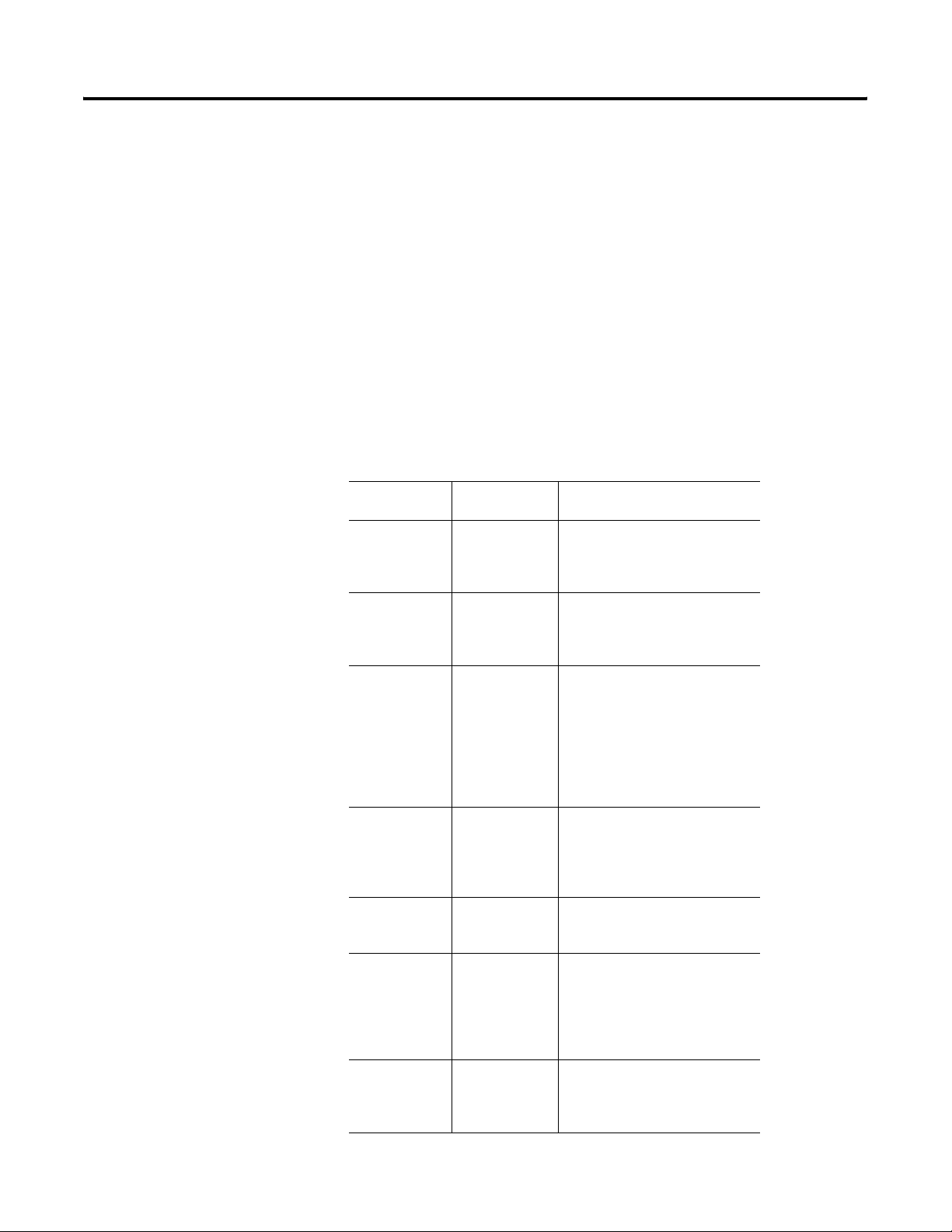
Throughout this manual, when necessary we use notes to make you aware of
safety considerations.
WARNING
IMPORTANT
ATTENTION
SHOCK HAZARD
BURN HAZARD
Identifies information about practices or circumstances
that can cause an explosion in a hazardous environment,
which may lead to personal injury or death, property
damage, or economic loss.
Identifies information that is critical for successful
application and understanding of the product.
Identifies information about practices or circumstances
that can lead to personal injury or death, property
damage, or economic loss. Attentions help you:
• identify a hazard
• avoid a hazard
• recognize the consequence
Labels may be located on or inside the equipment (e.g.,
drive or motor) to alert people that dangerous voltage may
be present.
Labels may be located on or inside the equipment (e.g.,
drive or motor) to alert people that surfaces may be
dangerous temperatures.
Page 3

Table of Contents
Preface
Overview of the ControlNet Ex
Media System
What’s in This Chapter . . . . . . . . . . . . . . . . . . . . . . . . . . . 1-1
Abbreviations and Symbols . . . . . . . . . . . . . . . . . . . . . . . . 1-2
Common Techniques . . . . . . . . . . . . . . . . . . . . . . . . . . . . 1-2
For More Information . . . . . . . . . . . . . . . . . . . . . . . . . . . . 1-2
Chapter 1
What This Chapter Contains . . . . . . . . . . . . . . . . . . . . . . . 1-1
Understand the ControlNet Ex Media System . . . . . . . . . . . 1-2
Understand ControlNet Ex Components . . . . . . . . . . . . . . . 1-4
Nodes . . . . . . . . . . . . . . . . . . . . . . . . . . . . . . . . . . . . . 1-4
Taps . . . . . . . . . . . . . . . . . . . . . . . . . . . . . . . . . . . . . . 1-4
Trunk Cable . . . . . . . . . . . . . . . . . . . . . . . . . . . . . . . . 1-5
Cable Connectors. . . . . . . . . . . . . . . . . . . . . . . . . . . . . 1-6
Trunk Terminator. . . . . . . . . . . . . . . . . . . . . . . . . . . . . 1-6
Tap Terminator . . . . . . . . . . . . . . . . . . . . . . . . . . . . . . 1-7
Segments. . . . . . . . . . . . . . . . . . . . . . . . . . . . . . . . . . . 1-7
Fiber Repeater Hubs . . . . . . . . . . . . . . . . . . . . . . . . . . 1-7
Network . . . . . . . . . . . . . . . . . . . . . . . . . . . . . . . . . . . 1-8
Insulators . . . . . . . . . . . . . . . . . . . . . . . . . . . . . . . . . . 1-8
ControlNet Ex System Installation Requirements . . . . . . . . . 1-9
Certified Equivalent ControlNet Ex System Components 1-10
UL, cUL I/O Entity Parameters and Requirements . . . . . 1-11
European Community Directive Compliance . . . . . . . . . 1-12
EMC Directive . . . . . . . . . . . . . . . . . . . . . . . . . . . . . . . 1-12
Ex Directive. . . . . . . . . . . . . . . . . . . . . . . . . . . . . . . . . 1-13
What Is Next? . . . . . . . . . . . . . . . . . . . . . . . . . . . . . . . . . . 1-13
Plan a ControlNet Ex Media
System
Chapter 2
What This Chapter Contains . . . . . . . . . . . . . . . . . . . . . . . 2-1
Determine How Many Taps You Need. . . . . . . . . . . . . . . . 2-2
Connect Programming Devices in Safe Areas . . . . . . . . . . . 2-3
Coax Cable Type . . . . . . . . . . . . . . . . . . . . . . . . . . . . . . . 2-3
Fiber Media Type . . . . . . . . . . . . . . . . . . . . . . . . . . . . . . . 2-4
Determine Trunk Cable Section Lengths. . . . . . . . . . . . . . . 2-4
Determine Trunk Cable Section Length When
You Use a FLEX Ex Redundant ControlNet
Barrier Module. . . . . . . . . . . . . . . . . . . . . . . . . . . . . . . 2-6
Estimate Fiber Media Lengths . . . . . . . . . . . . . . . . . . . . . . 2-7
Determine How Many Trunk Terminators You Need . . . . . 2-7
Determine What Type of Connectors You Need . . . . . . . . . 2-8
Use Redundant Media in a Hazardous Area . . . . . . . . . . . . 2-10
Application Considerations . . . . . . . . . . . . . . . . . . . . . . . . 2-13
Understand Conductor Categories. . . . . . . . . . . . . . . . . 2-13
General Wiring Guidelines . . . . . . . . . . . . . . . . . . . . . . 2-14
Ferrite Beads. . . . . . . . . . . . . . . . . . . . . . . . . . . . . . . . . . . 2-15
Required Ferrite Beads. . . . . . . . . . . . . . . . . . . . . . . . . 2-15
Add Ferrite Beads . . . . . . . . . . . . . . . . . . . . . . . . . . . . 2-16
i Publication CNET-IN003A-EN-P - January 2006
Page 4

Table of Contents ii
Install a ControlNet Ex Media
System
Order Components . . . . . . . . . . . . . . . . . . . . . . . . . . . . . . 2-17
General Planning . . . . . . . . . . . . . . . . . . . . . . . . . . . . . 2-17
Plan a Segment . . . . . . . . . . . . . . . . . . . . . . . . . . . . . . 2-17
Plan Your Network . . . . . . . . . . . . . . . . . . . . . . . . . . . 2-18
Order Parts . . . . . . . . . . . . . . . . . . . . . . . . . . . . . . . . . 2-18
What Is Next? . . . . . . . . . . . . . . . . . . . . . . . . . . . . . . . . . . 2-20
Chapter 3
What This Chapter Contains . . . . . . . . . . . . . . . . . . . . . . . 3-1
Install the Trunk Cable . . . . . . . . . . . . . . . . . . . . . . . . . . . 3-1
Wire External to Enclosures . . . . . . . . . . . . . . . . . . . . . 3-1
Wire Inside Enclosures. . . . . . . . . . . . . . . . . . . . . . . . . 3-2
Mount the Taps. . . . . . . . . . . . . . . . . . . . . . . . . . . . . . . . . 3-2
Select Where to Mount the Taps. . . . . . . . . . . . . . . . . . 3-2
Mount the Taps . . . . . . . . . . . . . . . . . . . . . . . . . . . . . . 3-3
Specifications . . . . . . . . . . . . . . . . . . . . . . . . . . . . . . . . . . 3-6
Install Fiber Hubs . . . . . . . . . . . . . . . . . . . . . . . . . . . . . . . 3-6
Installation in Zone 1 . . . . . . . . . . . . . . . . . . . . . . . . . . 3-7
Electrostatic Charge . . . . . . . . . . . . . . . . . . . . . . . . . . . 3-7
Select a Fiber Repeater Hub Mounting Location . . . . . . 3-8
Mount the Fiber Repeater Hub . . . . . . . . . . . . . . . . . . . 3-9
Connect the Fiber Repeater Hub to a ControlNet
Ex Network . . . . . . . . . . . . . . . . . . . . . . . . . . . . . . . . . 3-11
Install Cable Connectors . . . . . . . . . . . . . . . . . . . . . . . . . . 3-13
Collect Your Tools . . . . . . . . . . . . . . . . . . . . . . . . . . . . 3-13
Strip the Cable. . . . . . . . . . . . . . . . . . . . . . . . . . . . . . . 3-14
Test for Electrical Shorts and Continuity Between the
Center Conductor and the Shield . . . . . . . . . . . . . . . . . 3-19
Attach the Connectors to the Cable. . . . . . . . . . . . . . . . 3-20
Test for Electrical Shorts and Continuity Between the
Connector Body and Pin . . . . . . . . . . . . . . . . . . . . . . . 3-24
Connect Cable Sections . . . . . . . . . . . . . . . . . . . . . . . . . . . 3-25
Terminate Segments . . . . . . . . . . . . . . . . . . . . . . . . . . . . . 3-25
Connect Devices . . . . . . . . . . . . . . . . . . . . . . . . . . . . . . . . 3-27
Install the 1797-BCNR Module . . . . . . . . . . . . . . . . . . . . . . 3-28
Mounting Dimensions
Publication CNET-IN003A-EN-P - January 2006
Appendix A
What This Appendix Contains . . . . . . . . . . . . . . . . . . . . . . A-1
Tap Placement . . . . . . . . . . . . . . . . . . . . . . . . . . . . . . . . . A-1
Universal Mounting Bracket. . . . . . . . . . . . . . . . . . . . . . . . A-2
Page 5

Adjust the Cable Strip Tool
Protect Your System Against
Electrostatic Discharge
Index
Table of Contents iii
Appendix B
What This Appendix Contains . . . . . . . . . . . . . . . . . . . . . . B-1
Calibrate the Cutting Blades. . . . . . . . . . . . . . . . . . . . . . . . B-1
Reverse and Replace the Cutting Blades. . . . . . . . . . . . . . . B-3
Change the Memory Blade Holder . . . . . . . . . . . . . . . . . . . B-5
Appendix C
Publication CNET-IN003A-EN-P - January 2006
Page 6

Table of Contents iv
Publication CNET-IN003A-EN-P - January 2006
Page 7
Preface
What’s in This Chapter
Use this manual to plan and install a ControlNet Ex media system.
This manual describes the required components of an intrinsically-safe
cable system and how to plan for and install these required
components.
This manual targets the configurion of a ControlNet Ex system.
However, since a ControlNet Ex system and a ControlNet system can
be linked, it may be necessary to introduce and refer to concepts on
the ControlNet side of the network.
Some configurations on a standard ControlNet system may not be
possible within a ControlNet Ex configuration. Many of the installation
methods and equipment for the ControlNet Ex system is the same as
those available for the ControlNet system. However, some differences
do exist. As you use this manual, note these differences.
The following tables describe where specific information is found in
this manual.
For See Chapter
Help understanding the ControlNet Ex Media System 1
Help planning a ControlNet Ex Media System 2
Installation of a ControlNet Ex Media System 3
For See Appendix
Mounting dimensions (taps, universal mounting
bracket, and repeater)
Adjusting the cable strip tool B
Protecting your system against electrostatic discharge C
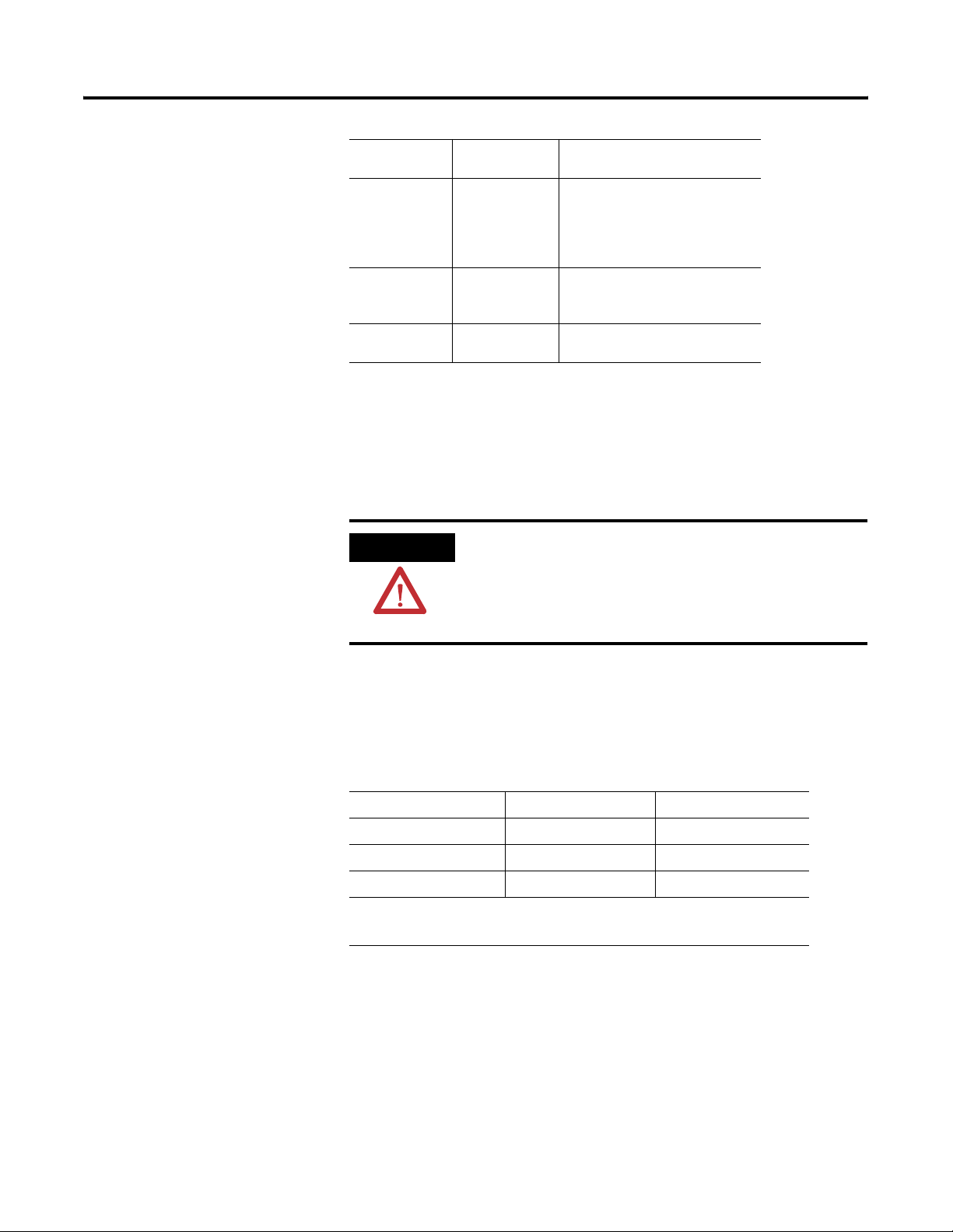
ATTENTION
You must have fundamental knowledge about
A
electronics and electrical codes to interpret and
apply the concepts in this manual.
1 Publication CNET-IN003A-EN-P - January 2006
Page 8
Preface 2
Abbreviations and Symbols
Common Techniques
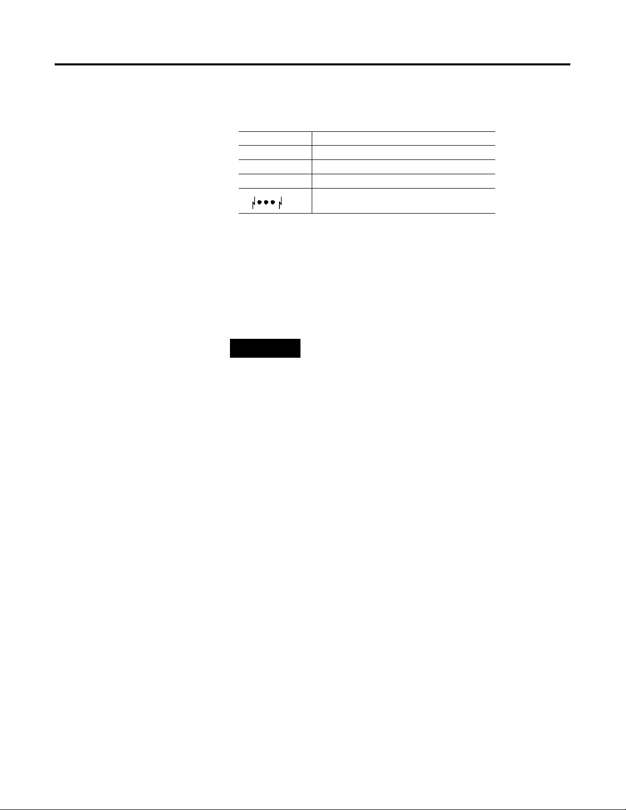
The following table explains abbreviations and symbols we use in this
manual.
This Means
PVC cable polyvinyl chloride cable
FEP cable fluorinated ethylene propylene cable
PLC processor Allen-Bradley programmable logic controller
network continues (other nodes not shown)
We use the following conventions throughout this manual:
• bulleted lists indicate information, not procedural steps
• numbered lists indicate sequential step
TIP
This symbol identifies helpful tips.
For More Information
For more information, refer to the following:
• Electronic Data Sheets:
http://www.ab.com/networks/eds/index.html
• RSNetWorx and RSLinx Software Demos and Tutorials
Publication CNET-IN003A-EN-P - January 2006
Page 9
Chapter
1
Overview of the ControlNet Ex Media System
What This Chapter Contains
Use this chapter to familiarize yourself with the ControlNet Ex media
system. The following table describes what this chapter contains and
where to find specific information.
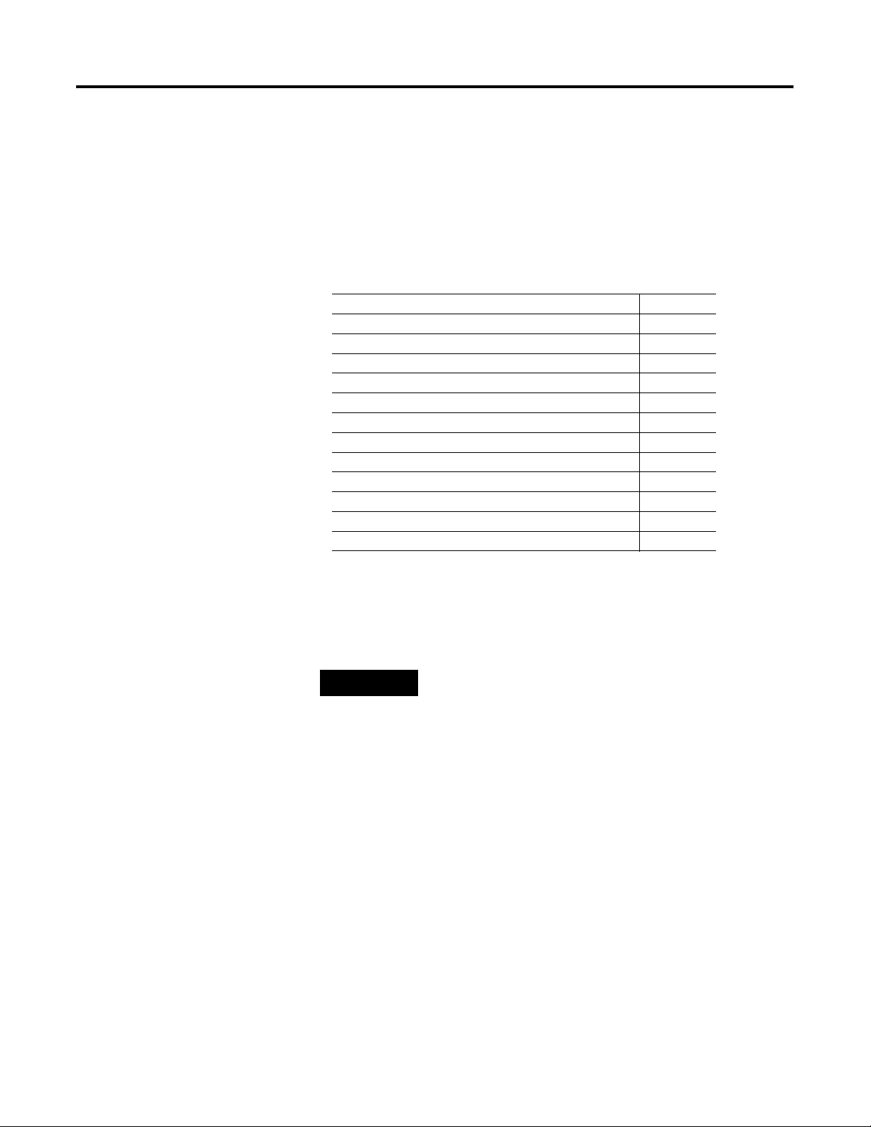
For Information On See Page
Understand the ControlNet Ex Media System 1-2
Understand ControlNet Ex Components 1-4
ControlNet Ex System Installation Requirements 1-9
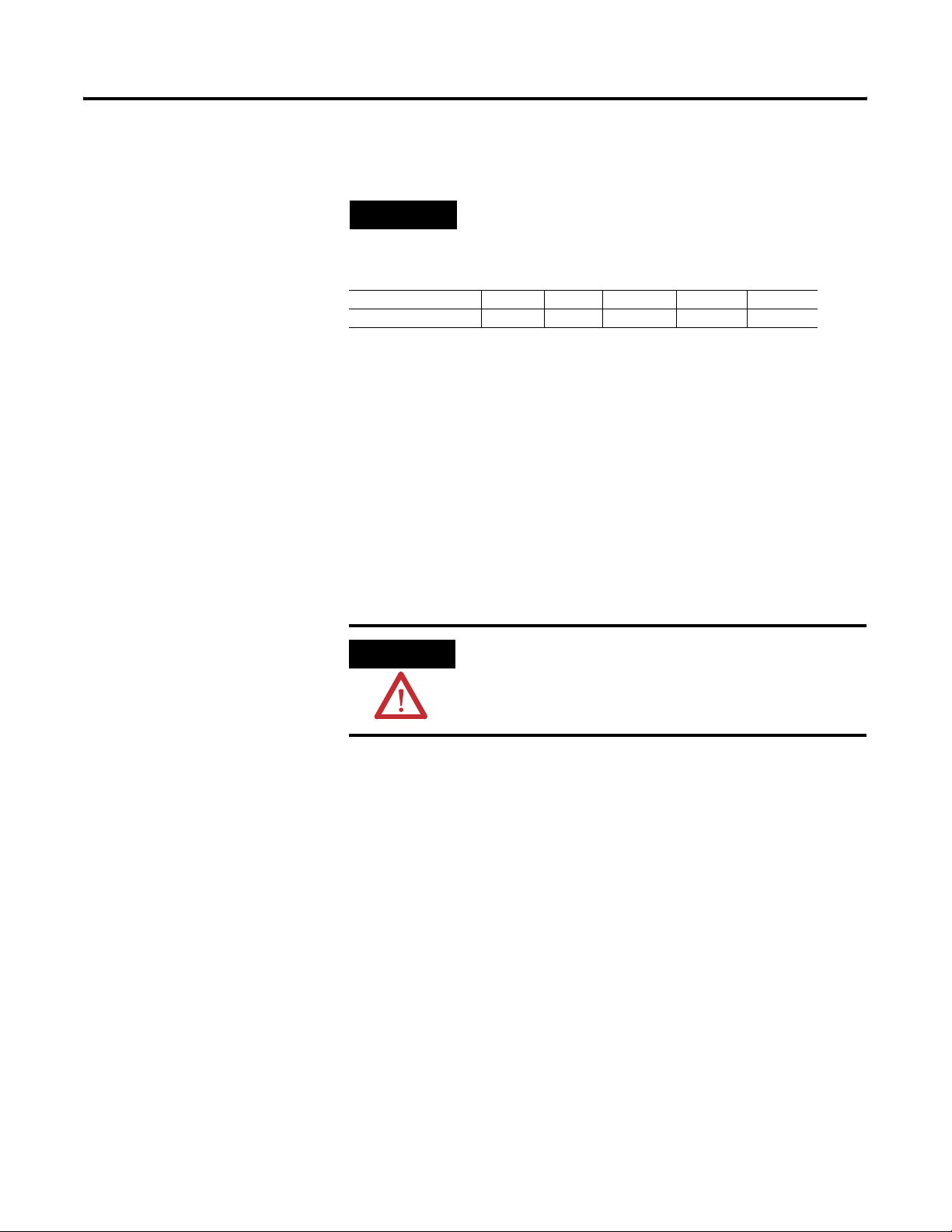
This system is an intrinsically-safe system specifically designed for use
in hazardous areas.
TIP
TIP
For information on installation requirements for
hazardous areas, refer to NFPA 70 (National Electrical
Code NEC), Article 500.
This publication describes how to plan and install a
ControlNet Ex media system in a hazardous area.
Refer to the following publications for information
on how to plan and install a coax and fiber media
system in a non-hazardous environment:
• CNET-IN002, ControlNet Coax Media Planning
and Installation Manual
• CNET-IN001, ControlNet Fiber Media Planning
and Installation Manual
ATTENTION
1 Publication CNET-IN003A-EN-P - January 2006
The ControlNet Ex media system cannot be used in a
safe environment after it has been exposed to signals
from a hazardous area.
Page 10
1-2 Overview of the ControlNet Ex Media System
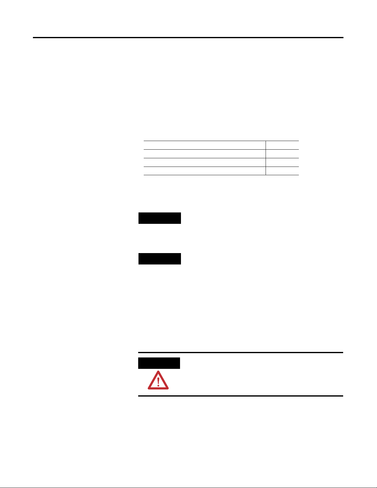
Understand the ControlNet Ex Media System
Safe Area
Coax Segment
TT
Network
N
Trunk Cable
N
Coax (1786) Fiber Hubs
The ControlNet Ex media system gives you the flexibility to design a
communication network for your particular application. To take full
advantage of this flexibility, spend sufficient time when you plan how
to install your network before you assemble any of the hardware.
For information on installing ControlNet media in a hazardous area,
refer to the ControlNet Coax Media Planning and Installation Manual,
publication CNET-IN002.
Use the following figures and term definitions to understand the
ControlNet Ex media system
Figure 1.1 ControlNet Coax to Fiber system for FLEX Ex
Hazardous Area
Coax Segment
T
N
Fiber Segment
T
H
T
H
Ex (1797) Fiber Hubs
T
Trunk Cable
NN
T
N
T
T
N
Term Means
Network • A collection of connected nodes
• A collection of nodes with unique addresses in the range of 1-99
• The connection paths between any pair of devices may include repeaters and bridges.
Segment • Trunk cable sections connected via taps with terminators at each end and with no
repeaters.
Trunk Cable • The bus or central part of a media system
Trunk Cable Section • A length of a cable between any two taps
Fiber Repeater Hub • Consists of a fiber repeater and fiber adapter
H
• The components reconstruct and retransmit all traffic on one fiber or coax segment
side to another coax or fiber segment side.
Tap • The connection between any device and the ControlNet Ex or ControlNet media
system
T
41326
Publication CNET-IN003A-EN-P - January 2006
Page 11
Overview of the ControlNet Ex Media System 1-3
Te rm M ean s
Node • Any physical device connecting to the ControlNet Ex or ControlNet media system that
requires a network address to function on the network
N
• A network may contain a maximum of 99 nodes
• This address must be in the range of 1...99 and be unique to that network.
Trunk Terminator • A 75 Ω resistor mounted in a BNC plug
Tap Terminator • Terminates a tap drop-cable that has yet to be connected to a node with a “dummy”
node
D
Barrier • Barrier for coax cable provides isolation between safe and hazardous areas
B
Repeater • A device that connects two or more segments together
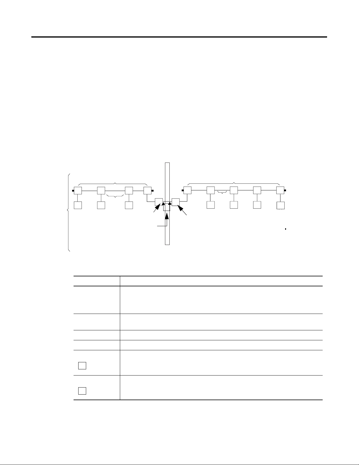
You can also use the 1797-BCNR FLEX Ex Redundant ControlNet
Barrier Module to interconnect between ControlNet coax and
ControlNet Ex networks. This module provides an alternative to
installing ControlNet Ex fiber repeater hubs.
Network
Figure 1.2 ControlNet Coax barrier system for FLEX Ex
1797-BCNR
Safe Area
Coax Segment
TT T
Trunk Cable
NN
N
B
Refer to Install the 1797-BCNR Module on page 3-28 for more
information.
Hazardous Area
Coax Segment
T
T
Trunk Cable
N
T
N
T
N
T
N
41326
Publication CNET-IN003A-EN-P - January 2006
Page 12
1-4 Overview of the ControlNet Ex Media System
Understand ControlNet Ex Components
The ControlNet Ex media system is comprised of these components:
• Nodes
• Taps
• Trunk cable
• Cable connectors
• Terminators
1
1
1
1
• Segments
• Fiber repeater hubs (option)
1
• Tap terminator
• Network
• Insulators
• Coax barrier
1
For information about purchasi ng t hese components see the Allen-Bradley C ontrolNet Media
Component List, publication AG-PA002.
(option)
1
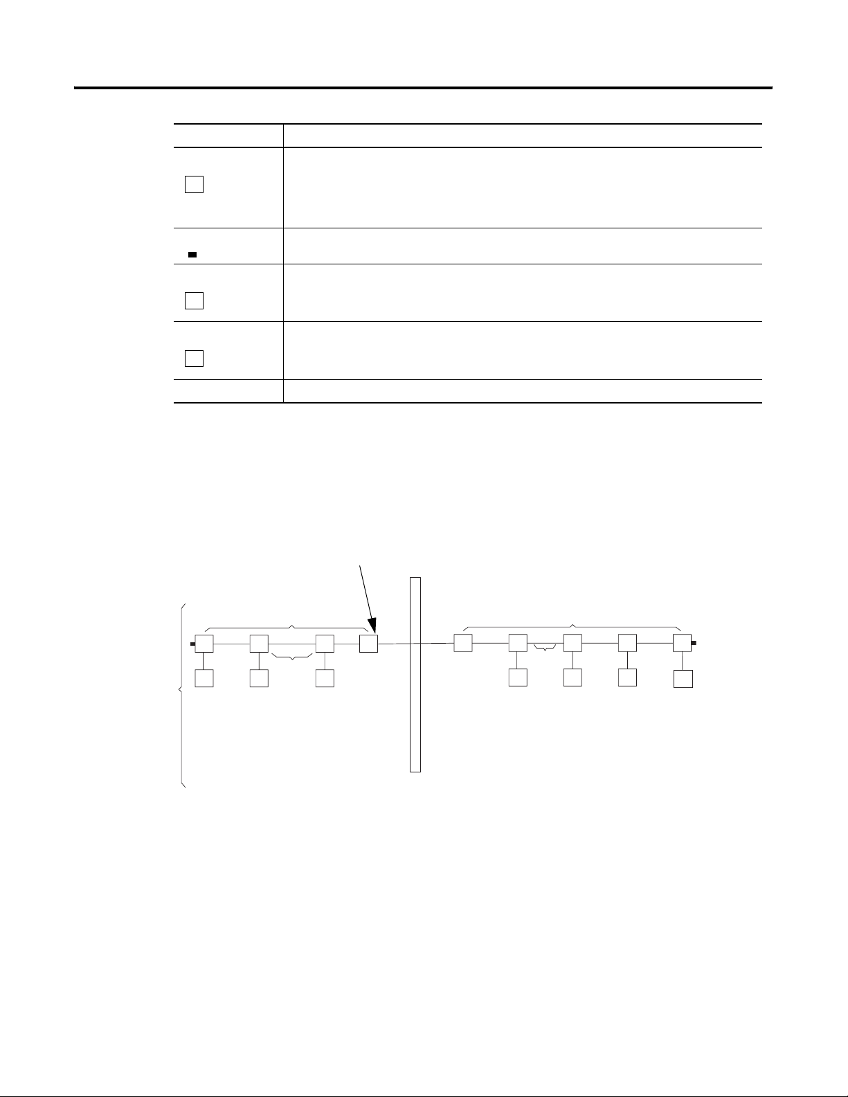
Nodes
Nodes are defined as physical devices connected to the ControlNet Ex
media system that require a network address to function on the
network.
TT
N
N
T
N
T
N
40953
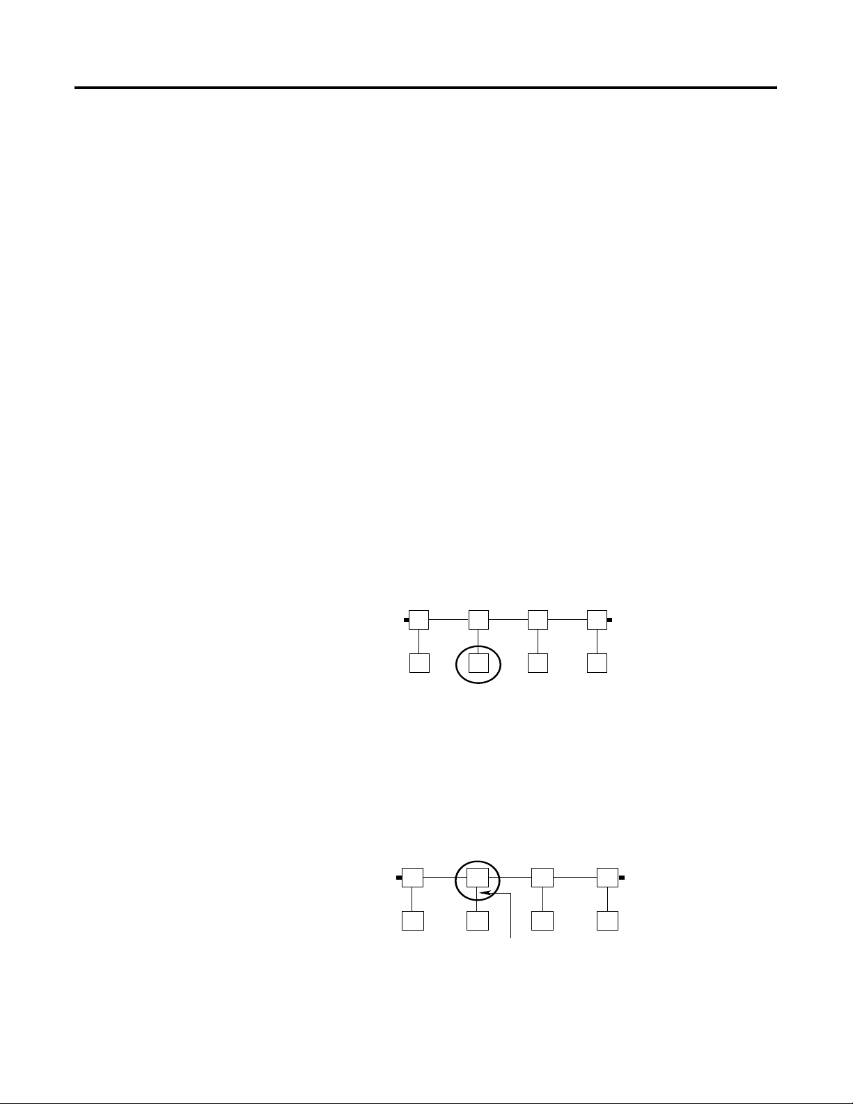
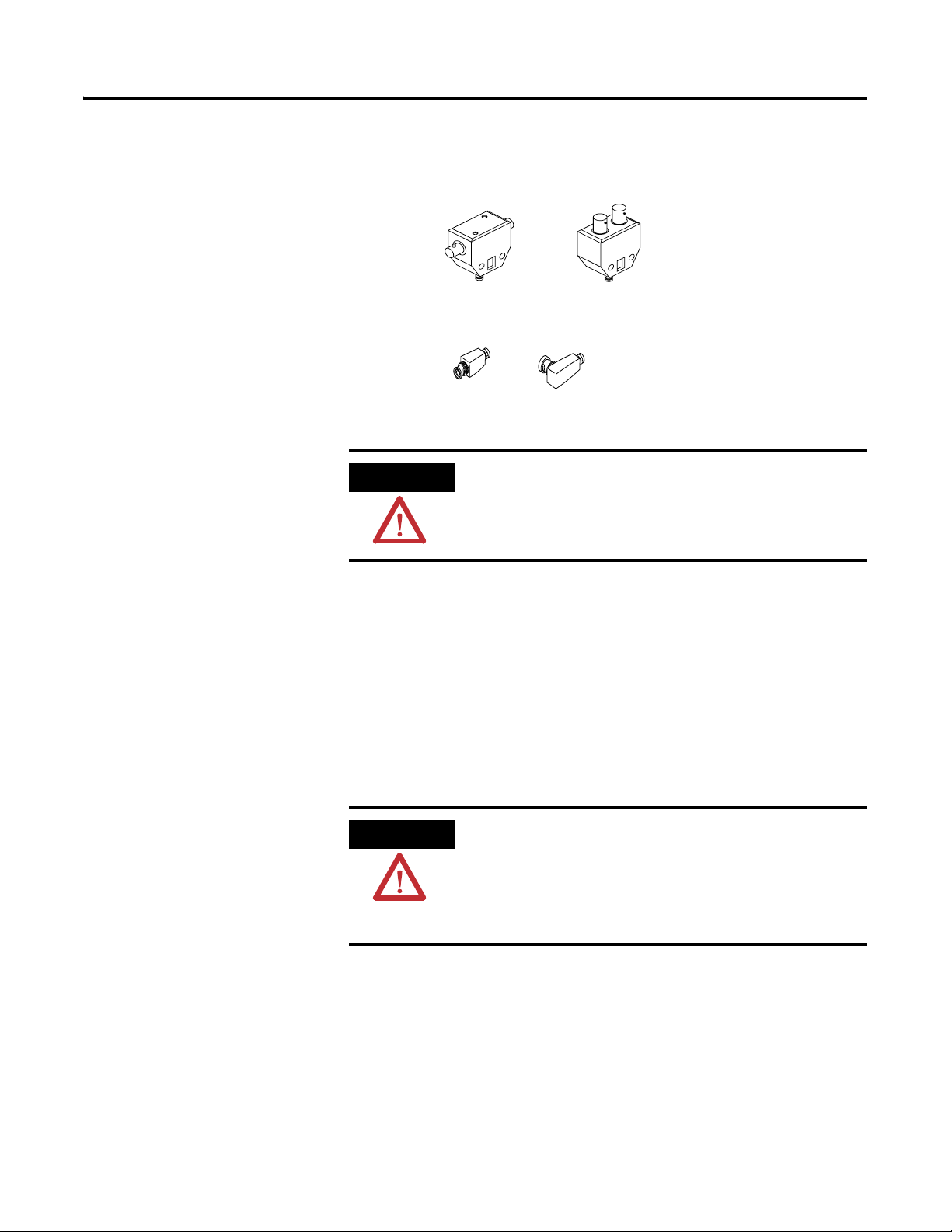
Tap s
Taps connect each node on a network to the coax media system via
an integral 1 m (39.6 in.) drop cable.
T
N
T
N
Drop Cable
1 m (39.6 in.)
TT
NN
40944
Publication CNET-IN003A-EN-P - January 2006
Page 13
Overview of the ControlNet Ex Media System 1-5
There are four styles of taps available with:
• T or Y placement of BNC connectors
T-tap
Y-tap
40955
• Straight or right-angle connector on the drop media
40956
ATTENTION
Straight
Right-angle
Use only intrinsically-safe taps in a ControlNet Ex
media system. Intrinsically-safe taps are marked
“ControlNet Ex Tap.”
See page 2-2 for detailed information on taps.
Trunk Cable
The trunk cable is the bus, or central part of the ControlNet Ex
coax media system. The trunk cable may be composed of multiple
sections of cable. Quad-shield RG-6 type coax cable can be used to
construct trunk cable sections.
ATTENTION
You must use either of these types of ControlNet Ex
trunk cable:
• 1797-RG6, Belden 3092A
• Belden 3092A blue quad-shield RG-6 type coax
cable
Publication CNET-IN003A-EN-P - January 2006
Page 14
1-6 Overview of the ControlNet Ex Media System
Cable Connectors
Use a cable connector (cat. no. 1786-BNC) to attach coax trunk cable
sections to the tap’s BNC connector.
T
N
T
Trunk Cable
NN
T
T
N
40957
Optional Connectors
Rockwell Automation also offers optional cable connectors for use in
your network configuration. See page 2-8 for available connectors.
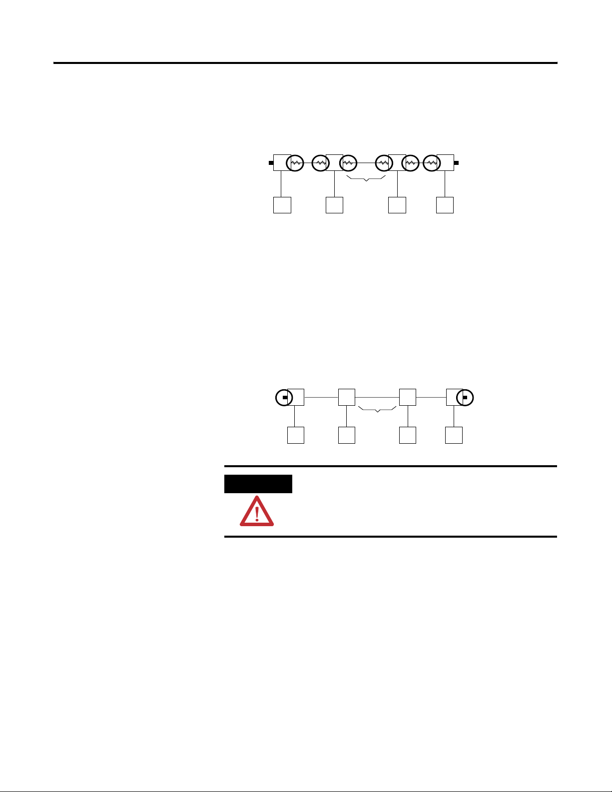
Trunk Terminator
A 75 Ω terminator (cat. no. 1797-XT) must be installed on the tap at
each end of a segment.
T
N
T
Trunk Cable
NN
T
T
N
40958
Publication CNET-IN003A-EN-P - January 2006
ATTENTION
Use only intrinsically-safe trunk terminators in a
ControlNet Ex media system. Intrinsically-safe trunk
terminators are marked “CNet Ex Trk Trm.”
Page 15
Overview of the ControlNet Ex Media System 1-7
Tap Terminator
A tap terminator (cat. no. 1797-TCAP) is available to terminate unused
taps.
Segment
1797-TCAP
T
Trunk Cable
TT
T
ATTENTION
N
Use only intrinsically-safe tap terminators in a
N
N
40959
ControlNet Ex media system. Intrinsically-safe tap
terminators are marked “CNet Tap Trm.”
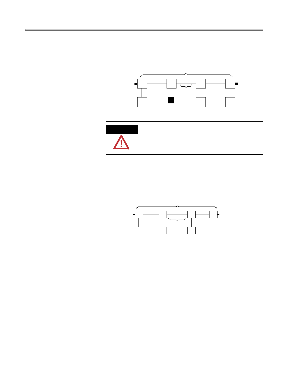
Segments
A segment is a collection of coax trunk cable sections, taps, and two
terminators.
Segment
T
NN
T
Trunk Cable
TT
N
N
40959
The total allowable length of a segment depends upon the number of
taps in your segment and the coax cable type used.
See page 2-1 for detailed information.
Fiber Repeater Hubs
You can use fiber as the connector from your safe area to your
hazardous area. Use fiber repeaters to connect the coax cable to the
fiber. Fiber repeater hubs increase the number of taps, extend the total
length of your segment, or create a star configuration (go off in
multiple directions from one point). The number of fiber repeater
Publication CNET-IN003A-EN-P - January 2006
Page 16
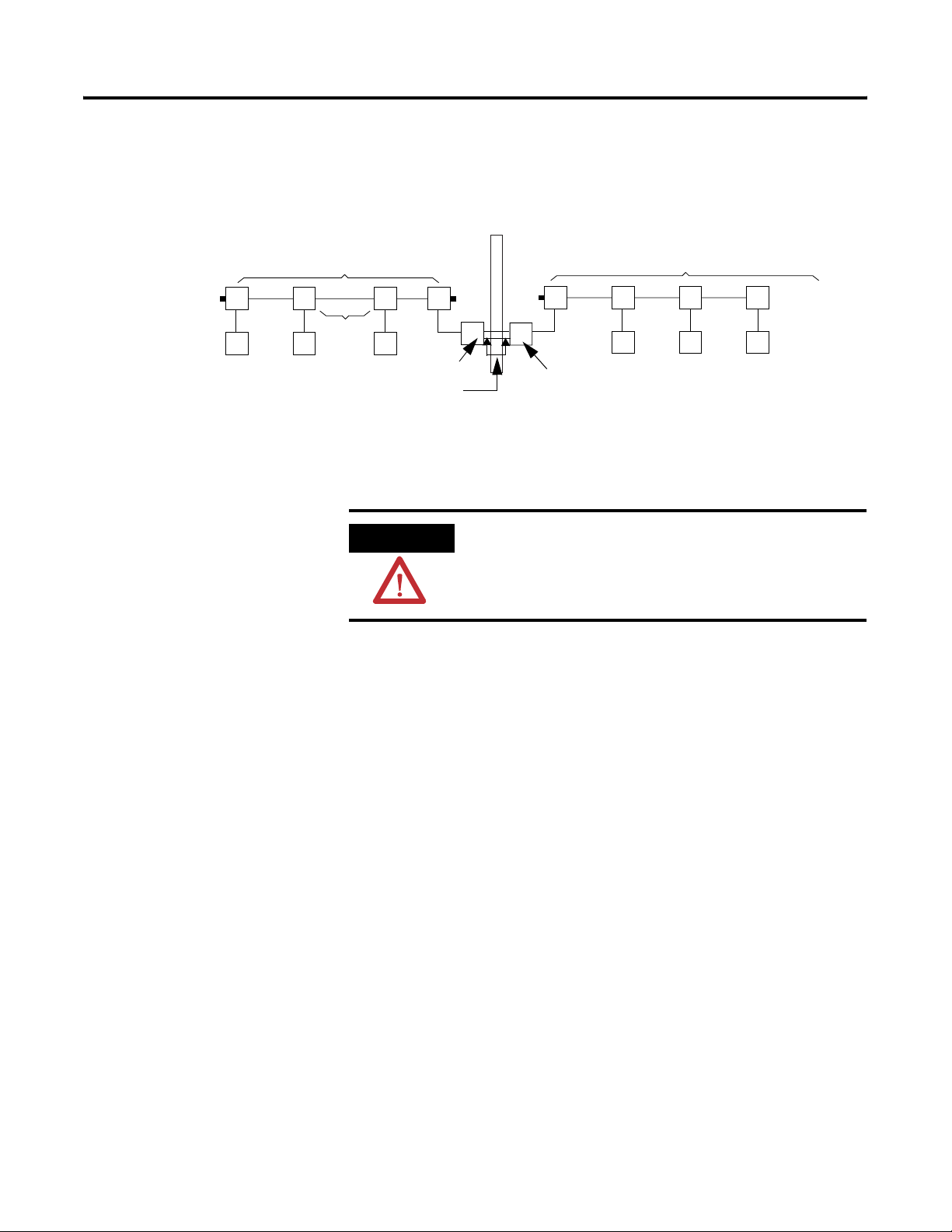
1-8 Overview of the ControlNet Ex Media System
hubs and cable length total are limited depending on your network
topology. You can have a maximum of 5 repeaters in series.
Safe Area
Coax Segment
T
NN
TTT T
Trunk Cable
Coax (1786) Fiber Hubs
Hazardous Area
Coax Segment
T
NN
Fiber Segment
HH
Ex (1797) Fiber Hubs
TT
NN
41327
When you insert a fiber repeater hub into your cable system, you
create a new segment. The same restrictions on the number of taps
and cable length apply to this new segment.
ATTENTION
Use only the intrinsically-safe 1797 version of the
fiber repeater hub in the hazardous area.
Network
A ControlNet network is the collection of connected segments, fiber
repeater hubs, and nodes.
Insulators
The ControlNet Ex media system must maintain isolation from ground.
Many of the connectors have metal parts. These parts must be
insulated from ground contact by 500V insulation material. Insulators
are provided with ControlNet Ex media system components that
require insulation. For example, the ControlNet Ex taps are supplied
with an insulator kit.
A large variety of BNC connectors are available for use with the
ControlNet Ex media system. As a result, insulators for all types of
connectors are not available. In these cases, wrapping the exposed
metal with 500V insulation electrical tape is acceptable.
Publication CNET-IN003A-EN-P - January 2006
Page 17
Overview of the ControlNet Ex Media System 1-9
Two insulator kits are available:
• Catalog number 1797-BOOT provides standard BNC trunk cable
insulators.
• Catalog number 1797-INS provides a variety of the preformed
boots and insulators used with the ControlNet Ex system
products.
ControlNet Ex System Installation Requirements
You can connect a maximum of 48 ControlNet Ex taps with a total of
250m of coax cable when using fiber hub architecture. The maximum
distance increases to 1000m when you use only 2 taps.
Refer to Determine Trunk Cable Section Lengths on page 2-4 and see
the table below for more information.
Catalog
Number
1797-RPA ControlNet Ex
1797-RPFM ControlNet Ex
1797-ACNR15 Redundant
1797-BCNR FLEX Ex
1797-TCAP ControlNet Ex
1797-TPx ControlNet Ex
1797-XT ControlNet Ex
Catalog Name Description
Represents one ControlNet Ex
Modular
Repeater Adapter
Fiber Repeater
Module, Medium
Distance
Media
ControlNet Ex
Adapter
Redundant
ControlNet
Barrier Module
Tap (Dummy)
Terminator
Coax Tap
Trunk Terminator
node and must be connected to a
coax trunk cable by
1797-TPx
Allows connection of a maximum
of two devices per 1797-RPA and
is powered directly by 1797-RPA
Represents one ControlNet Ex
node and must be connected to a
coax trunk cable by
1797-TPx -each one with two
redundant output channels that
are connected to different
ControlNet Ex networks (coax
cables and 1797-TPx)
Galvanic isolation barrier for
signal between the non-intrinsic
ControlNet system an
intrinsically-safe ControlNet Ex
system.
Represents one ControlNet Ex
node and is a simple capacitor
(56pF) with a coax connector
Four types of connections
available: S (straight T-tap), R
(right angle T-tap), YS (straight
Y-tap), and YR (right angle Y-tap) -
a maximum of 48 taps can be
connected by coax trunk cable
Simple resistor (75 Ω) with coax
connector that must be on each
end of the ControlNet Ex coax
trunk for termination
Publication CNET-IN003A-EN-P - January 2006
Page 18
1-10 Overview of the ControlNet Ex Media System
Catalog
Number
1786-RG6 Quad-Shield,
1786-BNCP,
-BNCJ, BNCJI
1797-BOOT FLEX Ex Boot
Catalog Name Description
Maximum (functional) length
RG-6 75Ω Coax
Trunk Cable
Standard Coax
Trunk Cable BNC
Couplers
Insulator Kit
between two 1797-TPx is 3280ft
(1000m) - each 1797-TPx reduces
the (functional) coax cable length
by 16.3 m (53.4 ft)
Standard cable couplers
Replacement insulators
You can install fiber connecting the 1797-RPFM module with any
approved associated device throughout the safe location.
All cables and fiber media that are not light blue must be marked as IS
using the 1797-EXMK marking kit or other locally approved IS
identification or segregation method.
ATTENTION
You must isolate all metallic parts during the
installation of the ControlNet Ex system to prevent
an earth connection. Use dielectric-strength isolating
material. The isolating material must withstand
voltages > 500V ac.
Certified Equivalent ControlNet Ex System Components
You may use these items as equivalents for system components.
Component Catalog Number Source
Coax Trunk Cable 1797-RG6 Rockwell Automation
1
3092IS
3092A with blue jacket Belden Wire & Cable Co.
1 Belden Wire & Cable 1189A may be used, but with functional loss of communication distance
or nodes.
Belden Wire & Cable Co.
Publication CNET-IN003A-EN-P - January 2006
Page 19
Overview of the ControlNet Ex Media System 1-11
UL, cUL I/O Entity Parameters and Requirements
TIP
For more information on UL and cUL installation
requirements, refer to publication 1797-RM001, FLEX
Ex System Certification Reference Manual.
Te rm in al s Vt (V) It (mA) Groups C
Male Bus Connector 5.8 400 A-G 3.0 3.0
(µF) La (µH)
a
The entity concept allows interconnection of intrinsically-safe
apparatus with associated apparatus not specifically examined in
combination as a system when the approved values of V
of the associated apparatus are less than or equal to V
and I
t
of the intrinsically-safe apparatus and the approved values of Ca
I
max
of the associated apparatus are greater than Ci + C
and L
a
respectively for the intrinsically-safe apparatus.
L
cable
and I
oc
cable
or V
sc
and
max
and L
+
i
Wiring methods must be in accordance with the National Electric
Code, ANSI/NFPA 70, Article 504 and 505 or the Canadian Electric
Code CSA C22.1, Part 1, Appendix F. For additional information refer
to ANSI/ISA RP12.6.
WARNING
Substitution of components may impair the intrinsic
safety of this system.
AVERTISSEMENT: La substitution de composant peut
compromettre la securite intrinseque.
t
Publication CNET-IN003A-EN-P - January 2006
Page 20

1-12 Overview of the ControlNet Ex Media System
If fiber optic cable is provided with a metal shield, it must be
connected to a dedicated intrinsic safety ground in the
intrinsically-safe location and isolated in the non-intrinsically-safe
location or be connected to a ground in the hazardous location and
isolated in the intrinsically-safe location.
The glass fiber must have a minimum diameter of 6µm.
European Community Directive Compliance
The ControlNet Ex System has the CE mark. It is approved for
installation within the European Community or EEA regions. It has
been designed and tested to meet the following directives.
EMC Directive
The ControlNet Ex System is tested to meet the Council Directive
89/336/EC Electromagnetic Compatibility (EMC) by applying the
following standards, in whole or in part, documented in a technical
construction file:
• EN50081-2 — EMC - Generic Emission Standard, Part 2 -
Industrial Environment
• EN50082-2 — EMC - Generic Immunity Standard, Part 2 -
Industrial Environment
The ControlNet Ex System is intended for use in an industrial
environment.
Publication CNET-IN003A-EN-P - January 2006
Page 21

Overview of the ControlNet Ex Media System 1-13
Ex Directive
The ControlNet Ex System is tested to meet the Council Directive 94/9
EC (ATEX 100a) Equipment and Protective Systems Intended for Use
in Potentially Explosive Atmospheres by applying the following
standards:
• EN50014:1992, Electrical Apparatus for Potentially Explosive
Atmospheres
• EN50020:1994, Electrical Apparatus for Potentially Explosive
Atmospheres - Intrinsic Safety “i”
• EN50039:1980, Electrical Apparatus for Potentially Explosive
Atmospheres - Intrinsically-safe Electrical Systems “i”
• pr EN50284:1997, Special requirements for construction, test,
and marking of electrical apparatus of equipment group II,
category 1 G
What Is Next?
Now that you have a general understanding of the ControlNet Ex
media system, you are ready to go to Chapter 2 to design a ControlNet
Ex media system for your specific requirements.
Publication CNET-IN003A-EN-P - January 2006
Page 22

1-14 Overview of the ControlNet Ex Media System
Notes:
Publication CNET-IN003A-EN-P - January 2006
Page 23
Plan a ControlNet Ex Media System
Chapter
2
What This Chapter Contains
Read this chapter to determine your network requirements.
For See Page
Determine How Many Taps You Need 2-2
Connect Programming Devices in Safe Areas 2-3
Coax Cable Type 2-3
Fiber Media Type 2-4
Determine Trunk Cable Section Lengths 2-4
Estimate Fiber Media Lengths 2-7
Determine How Many Trunk Terminators You Need 2-7
Determine What Type of Connectors You Need 2-8
Use Redundant Media in a Hazardous Area 2-10
Application Considerations 2-13
Ferrite Beads 2-15
Order Components 2-17
After reading this chapter, consult engineering drawings of your
facility for specific information concerning the best location for
installing your network.
TIP
1 Publication CNET-IN003A-EN-P - January 2006
The ControlNet Ex media system is a ground-isolated
network. To help prevent accidental grounding:
• Properly select cable, connectors, and
accessories. Local agencies require use of these
items for instrinsically safe system certification.
• Use the supplied ight-blue intrinsically-safe
insulators and dust caps to cover exposed metal
parts.
• Any accessories should have a dielectric rating of
greater than 500V.
• Use good installation techniques.
• Use blue tape to help prevent metal-to-ground
connections.
Page 24
2-2 Plan a ControlNet Ex Media System
Determine How Many Taps You Need
The number of taps you need depends on the number of devices you
want to connect to the network. You need a tap for each node,
repeater, or fiber hub on the network.
If you plan to add nodes later, you should consider ordering and
installing the cable and connectors for these additional nodes when
you install the initial network. This will minimize disruption to the
network during operation.
TIP
A disconnected drop cable can cause noise to enter
the network. Because of this, we recommend that
you have only one unconnected tap per network
for maintenance purposes. Use a tap terminator,
catalog number 1797-TCAP, on any unconnected
drop cable.
TIP
If you are planning future installation of additional
nodes, and can tolerate losing communication for a
short time, do not install the tap. Instead, install a
BNC bullet connector, catalog number 1786-BNCJ.
See page 2-8 for more information on the 1786-BNC
bullet connector.
Ex Insulator Kit
With Intrinsically-safe
Insulators
30394-M
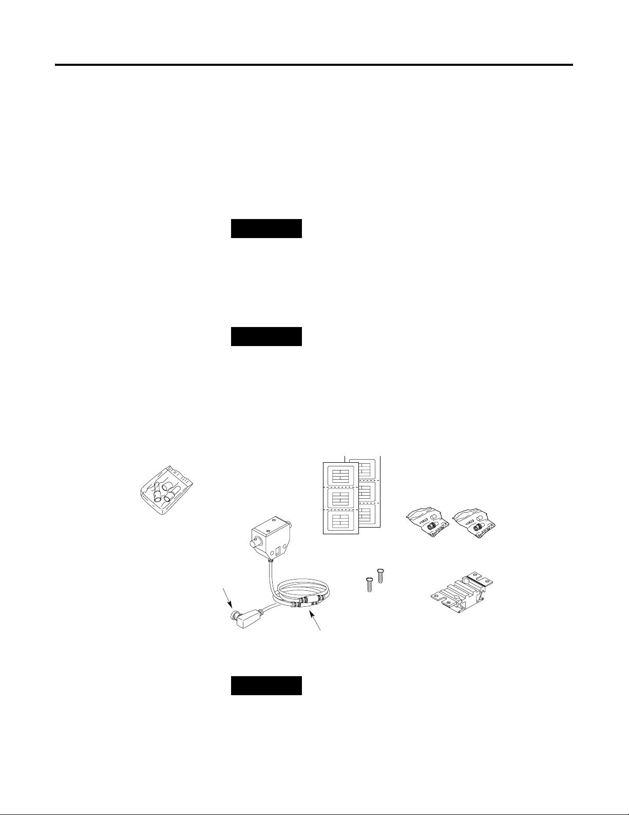
Each tap kit contains the following pieces:
Tap (1797-TPS, -TPR, -TPYS, -TPYR)
Dust Cap
For noise suppression, ferrite beads
are molded on the drop cable.
TIP
BNC Connector Kits
ControlNet Ex
Cable Labels
Screws
Universal Mounting Bracket
41329
We provide the light-blue intrinsically-safe insulators
and dust caps to cover exposed metal parts. Use
these items for instrinsically safe system certification
by local agencies.
Publication CNET-IN003A-EN-P - January 2006
Page 25
Plan a ControlNet Ex Media System 2-3
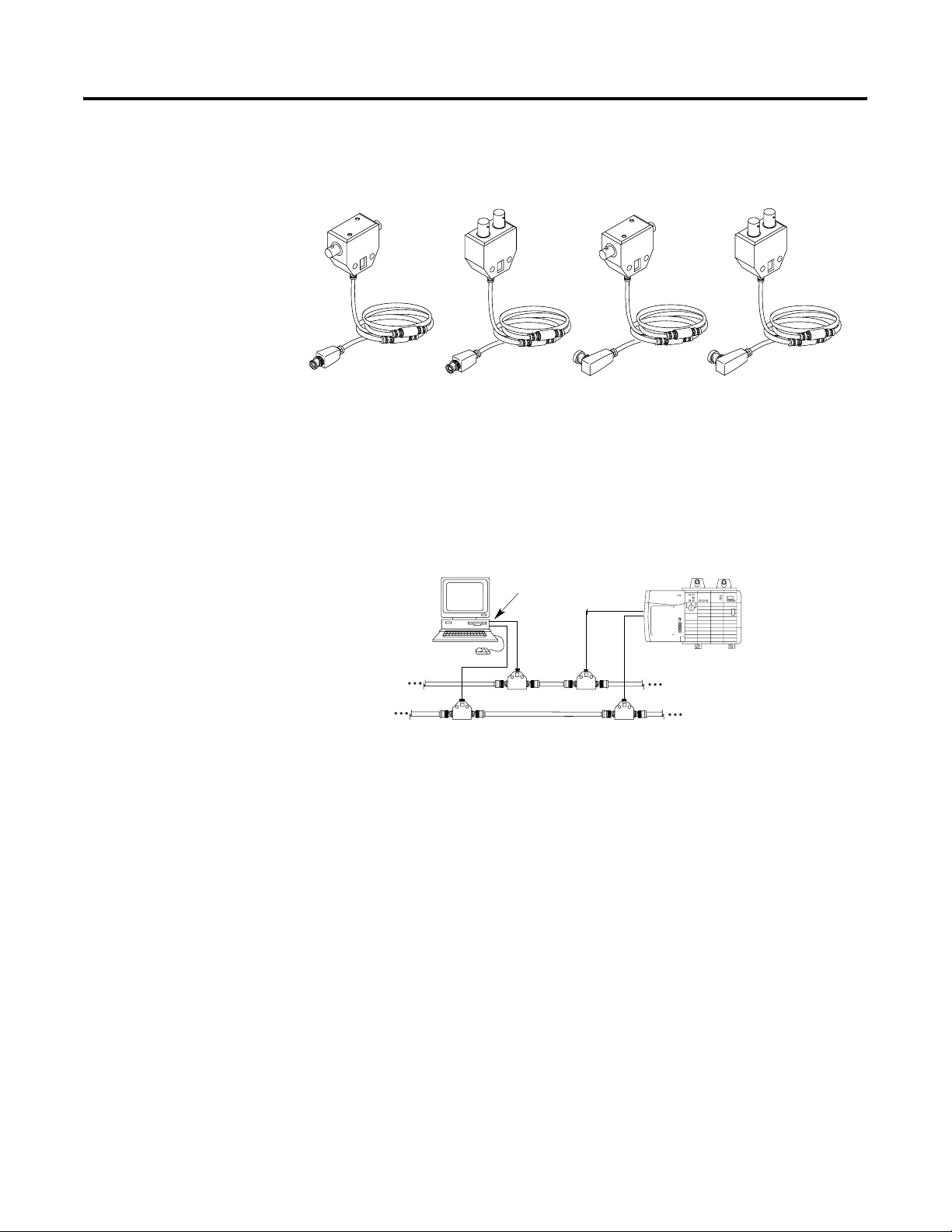
These tap kits are available (dust caps not shown):
Connect Programming Devices in Safe Areas
Straight T-Tap Straight Y-Tap Right-Angle T-tap
1797-TPS
1797-TPYS
Connect programming devices in safe areas to the ControlNet cable
system through a 1784-KTCX15 communication card. Use a
ControlNet tap to connect the communication card to the network.
Figure 2.1 Use a 1784-KTCX15 Communication Card on Coax Media
Programming
Terminal
1784-KTCX15
Right-Angle Y-Tap
1797-TPR 1797-TPYR
Node
41330
Coax Cable Type
41331
You must use 1786-RG6, Belden 3092A, or Belden 3092A blue quadshield RG-6 coax cable as the ControlNet Ex trunk cable.
Publication CNET-IN003A-EN-P - January 2006
Page 26
2-4 Plan a ControlNet Ex Media System
Fiber Media Type
Determine Trunk Cable Section Lengths
Trunk Terminator
With
Intrinsically-safe
Insulator
Fiber media type specifications are listed below.
• Fiber type 62.5/125
µ
• Connector type ST (plastic or ceramic)
• Operating wavelength 1300 nm
• Optical power budge 13.3 dB
You should install all fiber for your ControlNet Ex cable system in
accordance with the regulations contained in applicable country
codes, state codes, and applicable municipal codes (for example,
National Electric Code). All metal connectors must be insulated
from the ground. Use blue ControlNet cable or the ControlNet Ex
Cable Marking Kit (1797-EXMK) to mark cable as intrinsically-safe.
When you use the 1797-EXMK, be certain to place one marker at
every meter of length.
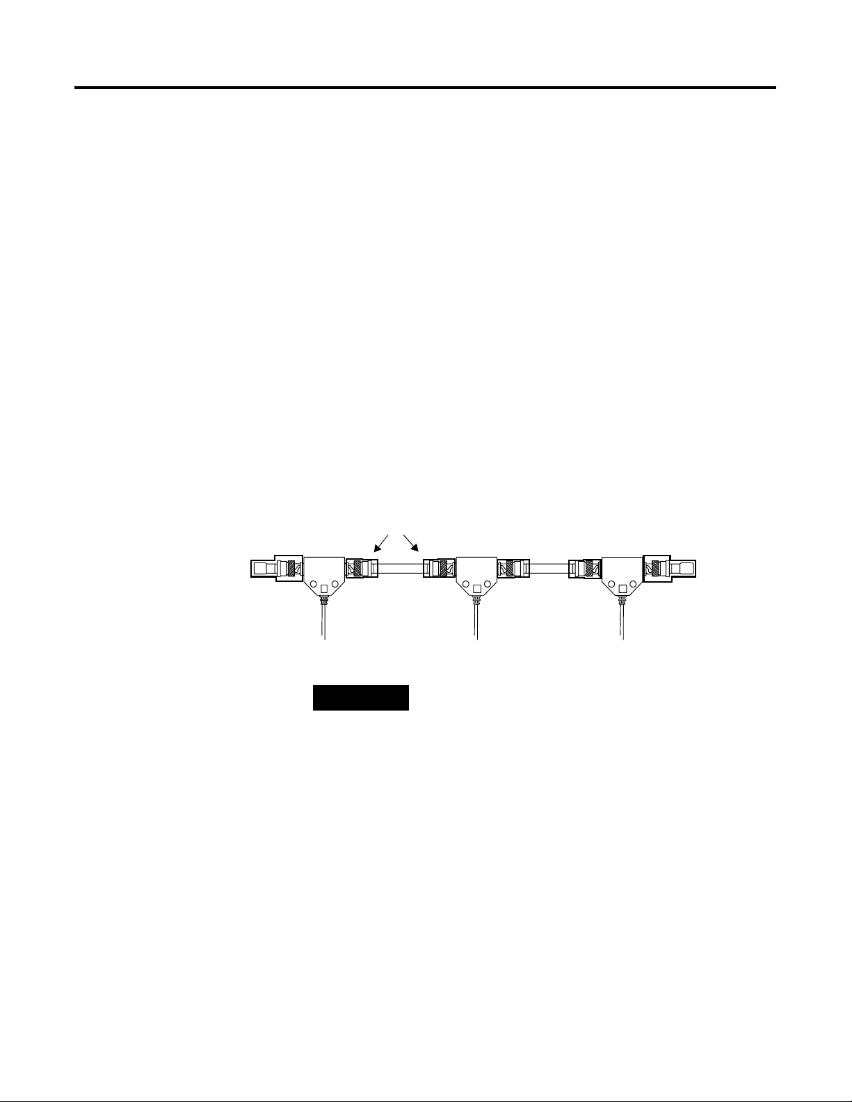
A segment is comprised of several sections of trunk cable separated
by taps. The total cable length of a segment is equal to the sum of all
of the trunk cable sections, including taps.
Tap TapTap
IS Insulators
Trunk Cable Section
Trunk Cable Section
Trunk Terminator
With
Intrinsically-safe
Insulator
30094-m
TIP
When determining the length of trunk cable sections,
measure the actual cable path as it is routed in your
network. Consider vertical dimensions as well as
horizontal dimensions. You should always calculate
the three-dimensional routing path distance when
determining cable lengths.
Cover all exposed metal on connectors with either
the intrinsically-safe insulators or other forms of
insulation.
Select the shortest path for routing the cable to
minimize the amount of cable you need. The specific
details of planning such a cable route depends upon
the needs of your network.
The total allowable length of a segment containing standard RG-6
quad-shield cable depends upon the number of taps in your
segment. There is no minimum trunk cable section length
Publication CNET-IN003A-EN-P - January 2006
Page 27
Plan a ControlNet Ex Media System 2-5
requirement. The maximum allowable total length of a segment is
1,000 m (3,280 ft) with two taps connected. Each additional tap
decreases the maximum length of the segment by 16.3 m (53.4 ft). The
maximum number of taps allowed on a segment is 48 with a
maximum length of 250 m (820 ft).
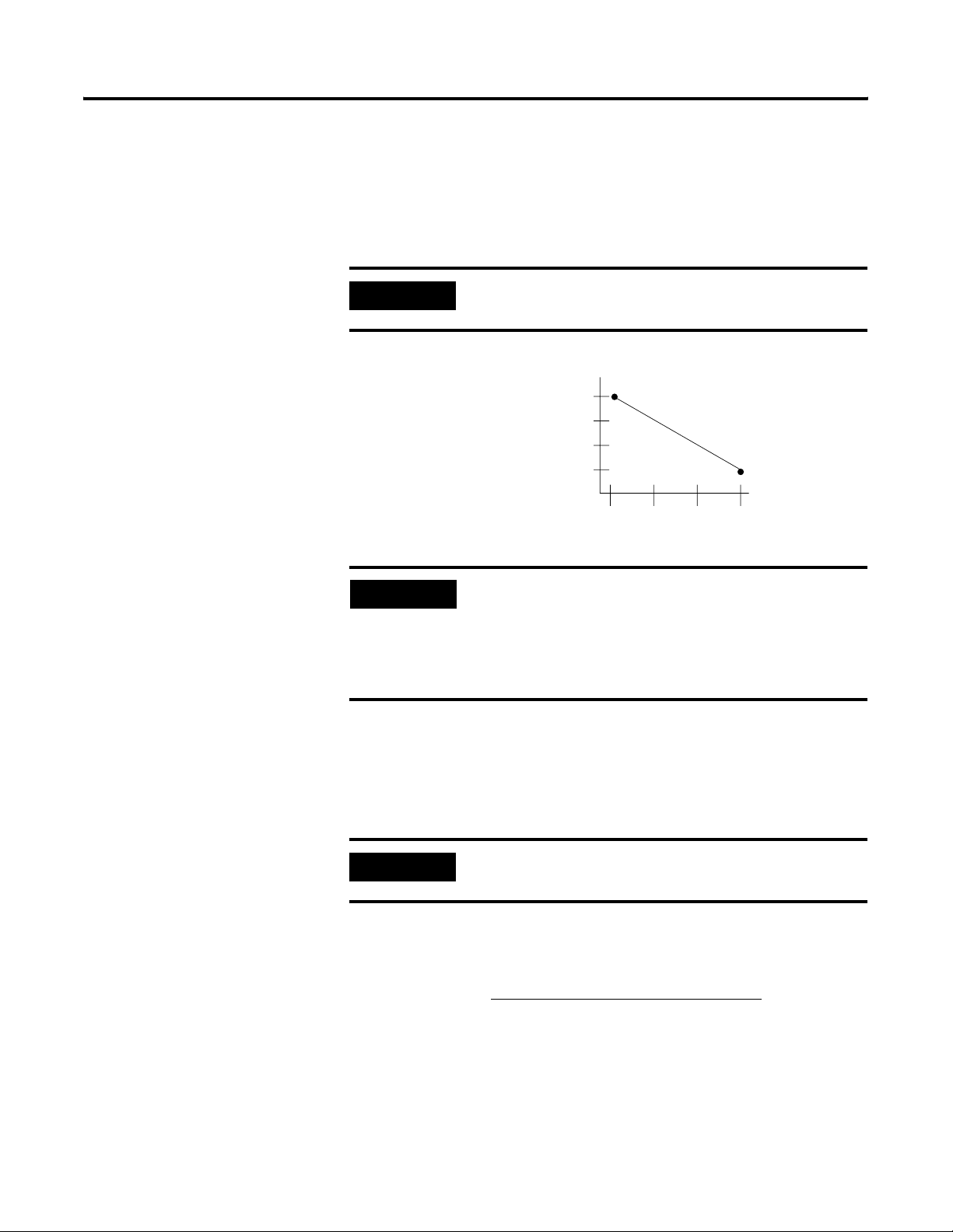
IMPORTANT
Figure 2.2 ControlNet Single Media Derating Curve
Maximum Allowable Segment Length
for FLEX Ex on ControlNet =
1000 m (3280 ft) - 16.3 m (53.4 ft) X
[Number of Taps - 2]
EXAMPLE
An allowable total length of RG-6 cable segment in your application
can be determined by using the equation below. Each additional tap
decreases the maximum length of the segment. The maximum
number of taps allowed on a segment is 48. Each additional tap
decreases the maximum length of the segment.
The derating curve is applicable only when the cable
meets ControlNet attenuation specifications.
)
t
1000 (3280)
(f
m
h
750 (2460)
t
g
n
e
500 (1640)
L
t
n
e
250 (820)
m
g
e
S
32 48
16
2
Number of Taps
30014-m
If your segment requires 10 taps, the maximum
segment length is:
1000m (3280 ft) - 16.3 m (53.4 ft) x [10 - 2]
1000m (3280 ft) - 130.4 m (427.7 ft)= 869.6 m
(2852.3 ft)
IMPORTANT
This equation applies when the cable does not meet
ControlNet attenuation specifications.
Maximum Allowable Segment Length of Cable =
(20.29 db - Number Of Taps in Segment *.32 db)
Cable Attenuation @ 10 MHz per 304 m (1000 ft)
Note: Cable attenuation is defined as the signal loss measured at 10 MHz per
304 m (1000 ft) of cable. Cable attenuation for ControlNet Ex cables is listed
in the ControlNet Ex Media Component List, publication AG-PA002.
X 304 m (1000 ft)
Publication CNET-IN003A-EN-P - January 2006
Page 28

2-6 Plan a ControlNet Ex Media System
EXAMPLE
IMPORTANT
For redundant media, decrease the number of taps by half, as shown
in the derating curve.
Figure 2.3 ControlNet Redundant Media Derating Curve
Maximum Allowable Segment Length
for FLEX Ex on ControlNet =
1000 m (3280 ft) - 16.3 m (53.4 ft) X
[Number of Taps - 2]
If your segment requires 3 taps using 1786-RG6
cable, the maximum segment length is:
([20.29 db - 3*.32 db] / 5.99 db] * 304)
(19.33 db / 5.99 db) * 304 = 982 m (3227 ft)
The total trunk cable length or number of taps can
be increased by installing a repeater hub on the
segment. This creates another segment.
)
t
1000 (3280)
(f
m
h
750 (2460)
t
g
n
e
500 (1640)
L
t
n
e
250 (820)
m
g
e
S
816 24
2
Number of Taps
30014-m
Publication CNET-IN003A-EN-P - January 2006
Determine Trunk Cable Section Length When You Use a FLEX Ex Redundant ControlNet Barrier Module
When you use a FLEX Ex Redundant ControlNet Barrier Module
(catalog no. 1797-BCNR), the total allowable length of a segment
containing standard RG-6 quad-shield cable depends upon the
number of taps in your segment. There is no minimum trunk cable
section length requirement. The maximum allowable length of a
segment that contains a 1797-BCNR module is 500 m. (1640 ft) with
two taps connected. Each additional tap decreases the maximum
length of the segment according to the derating curve. The maximum
number of taps allowed on a segment is 20 with a maximum length of
250 m (820 ft).
Page 29

500 m
(1640 ft)
250 m
(820 ft)
Plan a ControlNet Ex Media System 2-7
Segment Length m (ft)
Estimate Fiber Media Lengths
2
Number of Taps With One FLEX Ex Redundant ControlNet Barrier Module
20
The maximum length of a fiber media section for the 1797-RPFM
module is dependent on the quality of the fiber, number of splices,
and the number of connectors. The total attenuation for a cable
section must be less than 13.3 dB.
Typically, cable attenuation for a wavelength of 1300 nm is less than
1.5 dB/km.
IMPORTANT
Avoid joining cable with connectors as much as
possible. Connectors can cause considerable
attenuation and limit the maximum length of your
system. Be sure to check the attenuation of each
cable sections after the cable is installed.
Determine How Many Trunk Terminators You Need
You must use 75 Ω trunk terminators equipped with intrinsically-safe
insulators (cat. no. 1797-XT) at the end of each segment in the
ControlNet Ex cable system.
1797-XT
Intrinsically-safe Insulator
Publication CNET-IN003A-EN-P - January 2006
Page 30

2-8 Plan a ControlNet Ex Media System
After you have determined the number of segments in your network,
multiply this number by two to determine how many terminators you
need for your network.
IMPORTANT
To comply with intrinsic safety standards, be sure to
cover the exposed metal with the intrinsically-safe
insulator provided with each terminator.
Determine What Type of
Use the foll owing table to determine what type of connectors you need.
Connectors You Need
Use This BNC Connector To Cat. No.
cable connector Attach trunk cable sections to a tap’s BNC connector 1786-BNC
Use This Optional BNC Connector To Cat. No.
Bullet (Jack-to-jack) Reserve a space in the trunk cable for future installation of a
tap or to splice a trunk cable
Barrel (Plug-to-plug) Connect two adjacent taps without a trunk cable section
between them
1786-BNCJ
1786-BNCP
Isolated-bulkhead
(Jack-to-jack)
Tap Terminator Cap off installed taps that have yet to be connected to a node 1797-TCAP
Right Angle
(Jack-to-plug)
Go through grounded panel walls while maintaining the shield
isolation of the trunk cable
Provide a 90° bend in your cable (prevent bending your cable
excessively)
See Chapter 3 for the bend radius specification
1786-BNCJI
Refer to the ControlNet
Media System
Component List,
publication AG-PA002 for
the part number
Publication CNET-IN003A-EN-P - January 2006
Page 31

In This Example, ControlNet Ex
Cable:
• Enters and exits the panel
enclosure from the side
using isolated-bulkhead
connectors
• Contains two adjacent
taps connected by a barrel
connector
• Reserves one future tap
location with a bullet
Panel Wall
Bullet Connector
Right Angle
Connectors
Plan a ControlNet Ex Media System 2-9
Cable Enters and Exits
From the Side
Isolated-bulkhead
Connectors
Barrel
Connector
Taps
20091m
ATTENTION
TIP
Do not let any metallic surfaces on the BNC
connectors, plugs, or optional accessories touch
grounded metallic surfaces. This contact could cause
noise on the network. All exposed metal must be
covered with either intrinsically-safe blue insulators
or another form of insulation, such as tape with a
500V rating.
If you install a bullet connector for future tap
installations, count the bullet as one of the tap
allotments on your segment (and decrease the
maximum allowable cable length by 16.3 m [53.5 ft]).
This helps you avoid reconfiguring your network
when you install the tap.
Publication CNET-IN003A-EN-P - January 2006
Page 32

2-10 Plan a ControlNet Ex Media System
Use Redundant Media in a Hazardous Area
Safe Area
1786 Fiber
Repeater Hub
.
B-A
B-A
Allen-Bradley
Allen-Bradley
QUALITY
QUALITY
1797 - RPA
Net Ex
Control
Comm
Module
REPEATER ADAPTER
Status
Status
.
PWR
.
.
Coax Trunk Cable A =
Chan 1
1
43
12
+V -V +V -V
Recv Xmit Recv Xmit
.
You can run a second trunk cable between your ControlNet Ex nodes
for redundant media. With redundant media, nodes send signals on
two separate segments. The receiving node compares the quality of
the two signals and accepts the better signal to permit use of the best
signal. This also provides a backup cable should one cable fail.
Trunk cables on a redundant cable network are defined by the
segment number and the redundant trunk cable letter.
Actual ControlNet Ex products are labeled with these icons
(the shaded icon represent redundant media).
In this figure, the redundant cable trunk cable is trunk cable B.
Hazardous Area
1797 Fiber
Repeater Hub
.
1797 - RPFM
Net Ex
Control
FIBER MODULE
MEDIUM RANGE
.
Chan 2
.
.
.
B-A
B-A
Allen-Bradley
Allen-Bradley
QUALITY
QUALITY
Comm
Module
Status
Status
.
.
1797 - RPFM
1797 - RPA
Net Ex
Control
Net Ex
Control
FIBER MODULE
REPEATER ADAPTER
MEDIUM RANGE
.
PWR
.
.
Chan 1
Chan 2
1
43
12
+V -V +V -V
Recv Xmit Recv Xmit
.
Trunk Cable A =
Coax Trunk Cable B =
1786 Fiber
Repeater Hub
.
B-A
B-A
Allen-Bradley
Allen-Bradley
QUALITY
QUALITY
1797 - RPA
Net Ex
Control
Comm
Module
REPEATER ADAPTER
Status
Status
.
PWR
.
.
1
43
12
+V -V +V -V
Recv Xmit Recv Xmit
.
Trunk Cable B =
1797 Fiber
Repeater Hub
.
.
Chan 1
Chan 2
.
B-A
Allen-Bradley
QUALITY
1797 - RPFM
Net Ex
Control
FIBER MODULE
Comm
Module
MEDIUM RANGE
Status
Status
.
.
.
B-A
Allen-Bradley
QUALITY
1797 - RPFM
1797 - RPA
Net Ex
Control
Net Ex
Control
FIBER MODULE
REPEATER ADAPTER
MEDIUM RANGE
.
PWR
.
.
Chan 1
Chan 2
1
43
12
+V -V +V -V
Recv Xmit Recv Xmit
.
.
Node
Observe the following guidelines when planning a redundant media
system in a hazardous area.
• Route the two trunk cables (trunk cable A and trunk cable B)
differently to reduce the chance of both cables being damaged
at the same time.
• Each node on a redundant-cable network must support
redundant coax connections and be connected to both trunk
cables at all times. Any nodes connected to only one side of a
redundant-cable network will result in media errors on the
unconnected trunk cable.
41346
Publication CNET-IN003A-EN-P - January 2006
Page 33

Plan a ControlNet Ex Media System 2-11
• Install the cable system so that the trunk cables at any physical
device location can be easily identified and labeled with the
appropriate icon or letter. Each redundant ControlNet Ex device
is labeled so you can connect it to the corresponding trunk
cable.
• Both trunk cables (trunk cable A and trunk cable B) of a
redundant-cable network must have identical configurations.
Each segment must contain the same number of taps, nodes and
fiber repeaters. Connect nodes and fiber repeaters in the same
relative sequence on both trunk cables.
• Either side of a redundant-cable network may differ in cable
length. The total difference in length between the two trunk
cables must not exceed 800 m (2640 ft).
Trunk Cable A =
Trunk Cable B =
Trunk Cable B =
Trunk Cable A =
Segment 1
1
Node
1
Node
1
Node Supporting Redundant Media
Hazardous Area
Node
1
Node
Segment 2
.
.
B-A
B-A
Allen-Bradley
Allen-Bradley
QUALITY
QUALITY
Comm
Module
Status
Status
.
.
.
B-A
B-A
Allen-Bradley
Allen-Bradley
QUALITY
QUALITY
1797 - RPA
Control
Net Ex
Control
Comm
Module
REPEATER ADAPTER
Status
Status
.
PWR
.
.
Chan 1
Chan 2
1
43
12
+V -V +V -V
Recv Xmit Recv Xmit
.
.
1
1797 - RPA
Net Ex
Control
REPEATER ADAPTER
.
PWR
.
Chan 1
Chan 2
1
43
12
+V -V +V -V
Recv Xmit Recv Xmit
.
.
1797 - RPFM
Net Ex
FIBER MODULE
MEDIUM RANGE
.
1797 Fiber
Repeater
B-A
Allen-Bradley
QUALITY
Comm
Module
Status
Status
.
1797 - RPFM
1797 Fiber
Net Ex
Control
FIBER MODULE
MEDIUM RANGE
.
Repeater Hub
.
B-A
Allen-Bradley
QUALITY
1797 - RPA
Net Ex
Control
REPEATER ADAPTER
.
PWR
.
1
43
12
+V -V +V -V
Recv Xmit Recv Xmit
.
.
.
B-A
B-A
Allen-Bradley
Allen-Bradley
QUALITY
QUALITY
Comm
Module
Status
Status
.
.
Control
FIBER MODULE
MEDIUM RANGE
Chan 1
Chan 2
.
1797 - RPFM
1797 - RPA
Net Ex
Control
Net Ex
Control
FIBER MODULE
REPEATER ADAPTER
MEDIUM RANGE
.
PWR
.
.
Chan 1
Chan 2
1
43
12
+V -V +V -V
Recv Xmit Recv Xmit
.
.
1797 - RPFM
Net Ex
.
Node
1
41683
Publication CNET-IN003A-EN-P - January 2006
Page 34

2-12 Plan a ControlNet Ex Media System
Segment 1
1786 Node
• Avoid connecting a single node’s redundant trunk cable
connections on different segments; this will cause erratic
operation.
Hazardous AreaSafe Area
1786 Fiber
Repeater Hubs
B-A
Allen-Bradley
QUALITY
Comm
Module
Status
Status
.
B-A
Allen-Bradley
QUALITY
Comm
Module
Status
Status
.
.
Control
REPEATER ADAPTER
12
+V -V +V -V
.
.
Control
REPEATER ADAPTER
12
+V -V +V -V
.
.
B-A
Allen-Bradley
QUALITY
1797 - RPA
Net Ex
.
PWR
.
Chan 1
Chan 2
1
43
Recv Xmit Recv Xmit
.
.
B-A
Allen-Bradley
QUALITY
1797 - RPA
Net Ex
.
PWR
.
Chan 1
Chan 2
1
43
Recv Xmit Recv Xmit
.
1797 Fiber
Repeater Hubs
1797 - RPFM
Net Ex
Control
FIBER MODULE
MEDIUM RANGE
.
1797 - RPFM
Net Ex
Control
FIBER MODULE
MEDIUM RANGE
.
.
.
B-A
B-A
Allen-Bradley
Allen-Bradley
QUALITY
QUALITY
1797 - RPFM
1797 - RPA
Net Ex
Control
Net Ex
Control
FIBER MODULE
Comm
Module
REPEATER ADAPTER
MEDIUM RANGE
Status
Status
.
PWR
.
.
.
Chan 1
Chan 2
1
43
12
+V -V +V -V
Recv Xmit Recv Xmit
.
.
.
.
B-A
B-A
Allen-Bradley
Allen-Bradley
QUALITY
QUALITY
1797 - RPFM
1797 - RPA
Net Ex
Control
Net Ex
Control
FIBER MODULE
Comm
Module
REPEATER ADAPTER
MEDIUM RANGE
Status
Status
.
PWR
.
.
.
Chan 1
Chan 2
1
43
12
+V -V +V -V
Recv Xmit Recv Xmit
.
.
1797 Node
Segment 2
41348
A node supporting redundant trunk cable connections will function
even if trunk cable A is connected to the B connector on the node and
vice-versa. This makes cable fault indications (on the hardware or in
software) difficult to interpret and makes locating a bad cable segment
very difficult.
ATTENTION
Never connect parts of a ControlNet cable system to
those of a ControlNet Ex cable system. The 1786
fiber repeater hub and 1797 fiber repeater hub are
used to isolate the two sections of a ControlNet
network.
ATTENTION
ControlNet Ex products cannot be used in an
intrinsically-safe environment after they have been
exposed to non-intrinsically-safe signals.
Publication CNET-IN003A-EN-P - January 2006
Page 35

Plan a ControlNet Ex Media System 2-13
Application Considerations
The following guidelines coincide with the guidelines for the
installation of electrical equipment to minimize electrical noise inputs
to controllers from external sources contained in IEEE standard
518-1982. When planning your cable system keep these installation
considerations in mind.
ATTENTION
These guidelines apply only to noise coupling.
Intrinsic safety requirements for cable mounting are
of the highest priority.
Understand Conductor Categories
Conductors can be divided into three categories.
Category Includes
1 ac power lines
High-power digital ac I/O lines
High-power digital dc I/O lines
Power connections (conductors) from motion drives to motors
2 Analog I/O lines and dc power lines for analog circuits
Low-power digital ac/dc I/O lines
Low-power digital I/O lines
ControlNet Ex communication cables
3 Low-voltage dc power lines
Communication cables to connect between system components
within the same enclosure
Publication CNET-IN003A-EN-P - January 2006
Page 36

2-14 Plan a ControlNet Ex Media System
General Wiring Guidelines
Follow these guidelines with regard to noise coupling. Following
intrinsic safety requirements should prevent most or all of these
situations from occurring. These guidelines are provided as a general
reference for wiring.
• If wiring must cross power feed lines, it should do so at right
angles.
• Route wiring at least 1.5 m (5 ft) from high-voltage enclosures,
or sources of rf/microwave radiation.
• If the conductor is in a metal wireway or conduit, each section
of that wireway or conduit must be bonded to each adjacent
section so that it has electrical continuity along its entire length,
and must be bonded to the enclosure at the entry point.
For more information on general wiring guidelines, see the
Industrial Automation Wiring and Grounding Guidelines, publication
1770-4.1.
Wire External to Enclosures
Cables that run outside protective enclosures are relatively long.
To minimize cross-talk from nearby cables, you should maintain
maximum separation between the ControlNet Ex cable and other
potential noise conductors. Route your cable following these
guidelines:
Cable in a Contiguous
Metallic Wireway or
Conduit?
Yes 0.08 m (3 in.) Category-1 conductors of less than 20A
No 0.15 m (6 in.) Category-1 conductors of less than 20A
Route Your
Cable At Least
0.15 m (6 in.) ac power lines of 20A or more, up to 100 KVA
0.3 m (12 in.) ac power lines greater than 100 KVA
0.3 m (12 in.) ac power lines of 20A or more, up to 100 KVA
0.6 m (24 in.) ac power lines greater than 100 KVA
From Noise Sources of This Strength
Wire Inside Enclosures
Cable sections that run inside protective equipment enclosures are
relatively short. As with wiring external to enclosures, you should
maintain maximum separation between your ControlNet Ex cable and
Category-1 conductors.
Publication CNET-IN003A-EN-P - January 2006
Page 37

Plan a ControlNet Ex Media System 2-15
When you run cable inside an enclosure, route conductors external to
all raceways in the same enclosure, or in a raceway separate from
Category-1 conductors.
Route Your Cable At Least From Noise Sources of This Strength
0.08 m (3 in.) Category 1 conductors of less than 20 A
0.15 m (6 in.) ac power lines of 20A or more, up to 100 KVA
0.6 m (24 in.) ac power lines greater than 100 KVA
Surge Suppression
Transient electromagnetic interference (emi) can be generated
whenever inductive loads such as relays, solenoids, motor starters, or
motors are operated by hard contacts such as push-button or selector
switches. These wiring guidelines assume you guard your system
against the effects of transient emi by using surge-suppressors to
suppress transient emi at its source.
Inductive loads switched by solid-state output devices alone do not
require surge suppression. However, inductive loads of ac output
modules that are in series or parallel with hard contacts require
surge-suppression to protect the module output circuits as well as to
suppress transient emi.
Ferrite Beads
Ferrite beads provide additional suppression of transient emi.
Fair-Rite Products Corporation manufactures a ferrite bead
(part number 2643626502) that can be slipped over Category-2 and
Category-3 (RG-6 type trunk cable) conductors. You can secure them
with heat-shrink tubing or tie-wraps. A cable transient emi induced
onto the cable can be suppressed by a ferrite bead located near the
end of the cable. The ferrite bead will suppress the emi before it
enters the equipment connected to the end of the cable.
Required Ferrite Beads
Five ferrites come with each ControlNet Ex adapter. Four are identical
and are for use on the ControlNet Ex trunk cable (two for Segment 1
and two for Segment 2). The fifth ferrite is longer. You use this ferrite
on the adapter power cable.
Publication CNET-IN003A-EN-P - January 2006
Page 38

2-16 Plan a ControlNet Ex Media System
Add Ferrite Beads
Wrap the IS power input cable
two turns around the ferrite bead
before connecting the terminal
block to the adapter.
Five ferrite beads come with the
adapter. Four are short and
identical. Use these on the
ControlNet Ex trunk cable. The
fifth, longer ferrite bead is for the
adapter power cable.
42206
Add ferrite beads on the
ControlNet Ex trunk cable inside the
cabinet wherever the trunk cable
goes into or out of the cabinet.
Ferrite Beads
30890-M
Publication CNET-IN003A-EN-P - January 2006
Page 39

Plan a ControlNet Ex Media System 2-17
Order Components
Now that you are ready to begin ordering components, use these
guidelines to help you select components.
General Planning
The ControlNet Ex cable system is isolated from earth and must be
protected from inadvertent ground connections.
Plan a Segment
Refer to this list when you plan a segment.
• All connections to the trunk cable require a tap
• Taps may be installed at any location on the trunk cable
• Tap drop-cable length must not be changed
• Maximum number of taps = 48, with 250 m (820 ft) of standard
RG-6 trunk cable
• Maximum trunk cable length of RG-6 trunk cable = 1000 m
(3280 ft), with 2 taps
• 75 Ω trunk terminators are required on both ends
• One tap with an unconnected drop cable may be installed for
maintenance purposes
• Use BNC bullet connectors at future tap locations
• Do not mix redundant and non-redundant nodes
• Use ControlNet Ex tap terminators (1797-TCAP) for all other
unconnected drop cables
• Avoid high noise environments when routing cables
• A supplied ferrite toroid should be used on the ControlNet Ex
trunk as it enters and leaves control cabinets
Publication CNET-IN003A-EN-P - January 2006
Page 40

2-18 Plan a ControlNet Ex Media System
Plan Your Network
Refer to this list when you plan your network.
• Maximum of 99 nodes (excluding fiber repeater hubs)
• Fiber repeater hubs require a tap but are not counted as nodes
(they are included in the number of devices allowed per
segment [48])
• Fiber repeater hubs may be installed at any tap location along a
segment
• There can be only one path between any two points on a
network
• The configuration of both sides of a redundant segment must be
the same
• The total cable difference between the two sides of a redundant
network cannot exceed 800 m (2640 ft)
Order Parts
The following table contains a list of ControlNet Ex Components.
Refer to the ControlNet and ControlNet Ex Media System Components
List, publication AG-PA002, for a list of other ControlNet parts.
Item Cat. No. Guidelines
Taps
Straight T-tap
Straight Y-tap
Right-angle T-tap
Right-angle Y-tap
Trunk Terminators 1797-XT
Trunk Cable Use the ControlNet Ex Media System
Tap Terminator 1797-TCAP
1797-TPS
1797-TPYS
1797-TPR
1797-TPYR
(quantity of 50)
(quantity of 5)
You need a tap for each connection to the
trunk cable (nodes and repeaters).
Each tap kit contains: two BNC connector
kits, one dust cap, one universal mounting
bracket, ControlNet Ex cable labels and
two screws
You need a terminator for each end
of each segment.
Component List, publication AG-PA002,
to order your required length of cable.
Use the dummy load to plug into drop
cables that are not attached to a node.
Required Quantity
Number of repeaters x 2
Number of nodes
Number of segments x 2
Follow guidelines on page 2-4
of this document to determine
cable length
One for every drop cable that is
not attached to a node
1
+
Publication CNET-IN003A-EN-P - January 2006
Page 41

Plan a ControlNet Ex Media System 2-19
Item Cat. No. Guidelines
Coax Tool Kit 1786-CTK Use the tool kit to create your trunk cable
Required Quantity
One
to your specifications.
1
You will need to double your quantities when ordering components for a redundant cable system.
2
The connector kit may be shipped with two ferrules. The smaller diameter ferrule should not be used with ControlNet Ex applications.
1
Publication CNET-IN003A-EN-P - January 2006
Page 42

2-20 Plan a ControlNet Ex Media System
What Is Next?
After you gather all of the parts for your ControlNet Ex media system,
you are ready to go to Chapter 3 to begin the installation of your
network.
Publication CNET-IN003A-EN-P - January 2006
Page 43

Install a ControlNet Ex Media System
Chapter
3
What This Chapter Contains
Install the Trunk Cable
Follow the instructions in this chapter to install your ControlNet Ex
media system.
For See Page
Install the Trunk Cable 3-1
Mount the Taps 3-2
Specifications 3-6
Install Fiber Hubs 3-6
Install Cable Connectors 3-13
Connect Cable Sections 3-25
Terminate Segments 3-25
Connect Devices 3-27
Install the 1797-BCNR Module 3-28
TIP
When installing your trunk cable, observe your cable supplier’s
installation instructions and these guidelines.
You should read Chapter 2, Plan a ControlNet Ex
Network, before you install your network.
Wire External to Enclosures
When the RG-6 type coax cable is being pulled through multiple
conduit bends, follow these specifications.
For This Coax
Cable
PVC 42.75 kg (95 lbs) 76.2 mm (3.0 in.)
1 Publication CNET-IN003A-EN-P - January 2006
The Pull Strength Should Not
Exceed
The Bend Radius Should Not
Exceed
Page 44

3-2 Install a ControlNet Ex Media System
Wire Inside Enclosures
When the RG-6 type coax cable is not being pulled through conduit,
follow these specifications.
For This Coax Cable The Bend Radius Should Not Exceed
PVC 38.1 mm (1.5 in.)
Tap drop-cable 25.4 mm (1.0 in.)
The 1797-EXMK Cable Marking kit is available for clearly marking
drop cables and trunk cables as intrinsically-safe.
Mount the Taps
First select where you want to mount the taps, then use this mounting
procedure.
Select Where to Mount the Taps
There is no spacing requirement between taps; you can install two
adjacent taps if necessary by using a barrel connector (1786-BNCP).
IMPORTANT
Be certain that:
• you choose a convenient location to mount and route the cable.
• the location does not cause any cable bend-radii to exceed the
limits listed on pages 3-1 and 3-2.
If the barrel connector (1786-BNCP) is used, use an
intrinsically-safe insulator, the light-blue dust caps
we provide, or tape having a 500V insulation rating
to cover exposed metal parts. Local agencies require
their use for intrinsically-safe certification.
Publication CNET-IN003A-EN-P - January 2006
• you route the cable in accordance with intrinsically-safe cable
routing specifications.
• you do not mount the tap in a position that routes the drop
cable over any ac power terminals on nearby modules.
Page 45

Install a ControlNet Ex Media System 3-3
ATTENTION
Do not allow any metal portions of the tap, such as
the universal mounting bracket screws or
connectors, to contact any conductive material. This
contact could cause noise on the network.
Also be certain all exposed metal is covered by
either the intrinsically-safe insulators or tape having a
500V dielectric rating.
Mount the Taps
You can mount your ControlNet Ex taps (Y-tap and T-tap):
• to a universal mounting bracket, and then mount the tap and
bracket as an assembly.
• through the body holes in the tap using screws, flat washers,
and a tie wrap.
Once you have mounted your taps, you can store or discard any
unused universal mounting brackets.
TIP
See Appendix A for universal mounting bracket and
tap mounting dimensions.
Publication CNET-IN003A-EN-P - January 2006
Page 46

3-4 Install a ControlNet Ex Media System
Mount a Tap with a Universal Mounting Bracket
1. Align the universal mounting bracket with the mounting holes
on the tap.
2. Use the screws provided with the tap to attach the tap to the
universal mounting bracket.
Universal Mounting Bracket
Y-Ta p
Universal Mounting Bracket
(Provided With Tap)
Use only the screws that are packaged with the tap. They are the proper length and head style.
20084-M
ATTENTION
ATTENTION
Dust Cap
Dust Cap
T-Ta p
Do not over-tighten the screws. Over-tightening the
screws can damage the tap. The applied torque
should be 0.2-0.4 Nm (1-2 ft-lbs).
Do not remove the intrinsically-safe dust cap unless
the tap drop is connected to a ControlNet Ex
product.
20080-M
Publication CNET-IN003A-EN-P - January 2006
Page 47

Install a ControlNet Ex Media System 3-5
3. Mount the tap and bracket assembly to a DIN rail or another
mounting surface.
DIN Mounting Rail Another Mounting Surface
Universal Mounting Bracket
Universal Mounting Bracket
Use four screws to attach the universal
mounting bracket to another mounting
surface.
DIN Rail
Suitable Fixture
20081-M
Mount the universal mounting bracket on specified Allen-Bradley mounting rails or #3 style symmetrical DIN rails (35 mm X 7.5 mm [1.38 in. x 0.30 in.])
20082-M
Type of Rail Cat. No. Type of Rail Cat. No.
A-B rail 1492-N1 DIN rail #3 199-DR1
1492-N22 1492-DR5
1492-N44 1492-DR6
1492-DR7
ATTENTION
Use an intrinsically-safe insulator, the light-blue dust
caps we provide, or tape having a 500V insulation
rating to cover exposed metal parts. Local agencies
require their use for intrinsically-safe certification.
Publication CNET-IN003A-EN-P - January 2006
Page 48

3-6 Install a ControlNet Ex Media System
Mount a Tap Through the Body Holes
TIP
A suitable fixture (mounting surface) can be
conductive or grounded because the mounting holes
are electrically isolated.
Mount the tap to a suitable fixture by using a tie wrap, or screws and
flat washers.
Tie Wrap Screws and Flat Washers
Screws and Flat Washers
41645
Body Holes
ATTENTION
Tie Wra p
You can use a variety of screw types.
Do not over-tighten the screws. Over-tightening the
Body Holes
screws can damage the tap. The applied torque
should be 0.2-0.4 Nm (1-2 ft-lbs). Do not use screws
larger than #8 in these holes.
(Not Supplied)
41646
Specifications
Install Fiber Hubs
Publication CNET-IN003A-EN-P - January 2006
The following table lists the specifications for the ControlNet Ex taps.
Operating temperature -20 to 70 °C (-4 to 158 °F)
Storage temperature -40 to 85 °C (-40 to 185 °F)
Relative humidity 5 to 95% noncondensing
Read the following sections before installing a fiber repeater hub.
To Install a Fiber Repeater Hub, You Should See Page
Apply the Installation in Zone 1 and related intrinsically-safe
warnings and standards
Select where to mount the fiber repeater hub 3-8
Mount the fiber repeater hub 3-9
3-7
Page 49

Install a ControlNet Ex Media System 3-7
Installation in Zone 1
The 1797-RPA and 1797-RPFM modules must not be exposed to the
environment. You must install these modules in a metal enclosure.
This repeater hub has a protection factor of IP20.
Attention: Avoid electrostatic charge.
ATTENTION
These modules cannot be used in a hazardous
environment after they have been exposed to
non-intrinsically-safe signals.
Electrostatic Charge
Protect the system against electrostatic charge. Post a sign near this
module. The sign should read
Attention! Avoid electrostatic charge.
For your convenience, see page C-1 for signs that you can cut out.
European Community Directive Compliance
If this product has the CE mark it is approved for installation within
the European Community or EEA regions. It has been designed and
tested to meet the following directives.
EMC Directive
This product is tested to meet the Council Directive 89/336/EC
Electromagnetic Compatibility (EMC) by applying the following
standards, in whole or in part, documented in a technical construction
file:
• EN50081-2 EMC — Generic Emission Standard, Part 2 —
Industrial Environment
• EN50082-2 EMC — Generic Immunity Standard, Part 2 —
Industrial Environment
This product is intended for use in an industrial environment.
Publication CNET-IN003A-EN-P - January 2006
Page 50

3-8 Install a ControlNet Ex Media System
Ex Directive
This product is tested to meet the Council Directive 94/9 EC (ATEX
100a) Equipment and Protective Systems Intended for Use in
Potentially Explosive Atmospheres by applying the following
standards:
• EN50014:1992, Electrical Apparatus for Potentially Explosive
Atmospheres
• EN50020:1994, Electrical Apparatus for Potentially Explosive
Atmospheres - Intrinsic Safety “i”
• EN50039:1980, Electrical Apparatus for Potentially Explosive
Atmospheres - Intrinsically-safe Electrical Systems “i”
• pr EN50284:1997, Special requirements for construction, test,
and marking of electrical apparatus of equipment group II,
category 1 G
Inputs/Outputs
Do not apply any non-intrinsically-safe signals to the fiber modules.
When you use an intrinsically-safe electrical apparatus according to
EN50020, the European directives and regulations must be followed.
Select a Fiber Repeater Hub Mounting Location
The fiber repeater hub should be mounted:
• so that air can flow in and out of the air holes on the top and
bottom of the coax repeater.
For proper ventilation, be certain that there is a minimum of 5.1
cm (2 in.) from surrounding equipment.
• in a NEMA enclosure to provide protection from dust, moisture,
or corrosive atmospheres to a grounded metal plate, if possible.
ATTENTION
Be certain that the adapter and fiber modules are
secured together with DIN-rail anchors. Failure to do
so may result in the loss of communications or cause
damage to the modules.
Publication CNET-IN003A-EN-P - January 2006
Page 51

Install a ControlNet Ex Media System 3-9
Mount the Fiber Repeater Hub
Follow this procedure to mount the fiber repeater hub.
1. Position the module on a 35 mm x 7.5 mm (1.38 in. x 0.30 in.)
DIN rail (A-B part number 199-DR1) at approximately a 30°
angle.
41167
2. Hook the lip on the rear of the adapter onto the top of the DIN
rail, and rotate the module onto the rail.
41166
3. Press the adapter down onto the DIN rail until flush.
The locking tab should snap into position and lock the module
to the DIN rail.
Publication CNET-IN003A-EN-P - January 2006
Page 52

3-10 Install a ControlNet Ex Media System
4. If the adapter does not snap into position, use a screwdriver or
similar device to move the locking tab down while pressing the
module flush onto the DIN rail. Release the locking tab to lock
the module in place. If necessary, push up on the locking tab to
lock.
41168
5. Remove the adapter backplane connector cover.
6. Follow steps 1 through 4 to attach fiber modules to the DIN rail.
7. Once attached to the DIN rail, slide fiber modules to the left to
mate with the adapter.
Publication CNET-IN003A-EN-P - January 2006
41169
IMPORTANT
A DIN-rail end anchor (A-B part number 1492-EA35)
must be used on the left side of the adapter and to
the right side of the fiber module to keep the units
from moving.
8. Be certain the last fiber module has its backplane connector
cover in place.
9. Connect the adapter wiring as shown on page 3-11.
IMPORTANT
You can attach only two media modules to the
repeater adapter. If you exceed the module limit, you
may cause damage to the adapter or fiber modules
and void the intrinsically-safe certification.
Page 53

Install a ControlNet Ex Media System 3-11
Connect the Fiber Repeater Hub to a ControlNet Ex Network
1. Connect to the ControlNet Ex coax network with the drop line
of the Ex coax tap to the adapter BNC connector.
Intrinsically-safe
Insulator
41170
2. Connect the fiber media to the fiber module by attaching the
receive and transmit fibers to either the left or right set of receive
and transmit ports.
IMPORTANT
Make note of which fiber is receive and which is
transmit. These fibers must be interchanged at the
opposite end of the cable.
3. Attach the opposite ends of the cable to the other fiber module.
.
.
B-A
Allen-Bradley
QUALITY
Comm
Module
Status
Status
.
Control
REPEATER ADAPTER
12
+V -V +V -V
.
Receive
Transmit
ATTENTION
1797 - RPA
Net Ex
PWR
43
QUALITY
.
.
1
Recv Xmit Recv Xmit
1797 - RPFM
Net Ex
Control
FIBER MODULE
MEDIUM RANGE
.
Chan 1
Chan 2
.
.
B-A
Allen-Bradley
Use the blue intrinsically-safe insulators on all coax
.
B-A
Allen-Bradley
QUALITY
Comm
Module
Status
Status
.
1797 - RPA
Net Ex
Control
REPEATER ADAPTER
PWR
43
12
+V -V +V -V
.
B-A
Allen-Bradley
QUALITY
.
.
1
Recv Xmit Recv Xmit
.
1797 - RPFM
Net Ex
Control
FIBER MODULE
MEDIUM RANGE
.
Chan 1
Chan 2
.
Tr an sm i t
Receive
4131
BNC drop connectors as they are installed.
Publication CNET-IN003A-EN-P - January 2006
Page 54

3-12 Install a ControlNet Ex Media System
V
+
7
4. Apply +V and -V power from a 1797 power supply to the
adapter through a removable terminal block.
+V -V +V -
V-V+V-V
4129
Screw term inals and sprin g terminals are provided.
5. Strip the +V and -V wires to a length so that no bare conductor
shows after inserting the wires into position.
6. If you are using the spring terminals of the plug, insert a
screwdriver into the slot and carefully pry until the spring clamp
opens to accept the wire.
.
ATTENTION
IMPORTANT
Do not use any unused terminals on this adapter.
Using these terminals as supporting terminals can
result in damage to the module or unintended
operation of your system.
Make certain that you power this adapter with an
intrinsically-safe power supply. Do not exceed the
values listed in the specifications for this adapter.
Do not remove or replace a module when power is
applied. Interruption of the bus can result in
unintended operation or machine motion.
Be certain that all fiber modules are attached and
secured before you apply intrinsically-safe power to
the adapter. Failure to do so may cause damage to
the adapter and modules.
Publication CNET-IN003A-EN-P - January 2006
Page 55

Install a ControlNet Ex Media System 3-13
Install Cable Connectors
Wire Cutters
After you have mounted the taps, you need to attach cable connectors
to the ends of your trunk cable sections.
Collect Your Tools
To install the cable connectors, we recommend that you use the tools
in the ControlNet Coax Toolkit, catalog number 1786-CTK.
ControlNet Media Component List,
Publication AG-PA002
ControlNet Coax Media Planning and Installation
Guide, Publication CNET-IN002
Cable Strip Tool With Two Blade Cassettes
(One for PVC and One For FEP)
Crimp Tool
Knife
Calibration/Flare Tool
Memory Blade Holder
ATTENTION
Terminators and Extra Connectors
Memory Blade Cartridges (Contains Two Sets of
Memory Blades)
41902
Be certain that you calibrate the cable strip tool the
first time you use the tool and every time you change
the blade for both memory cartridges. Refer to
Appendix B for the proper calibration procedure.
Due to slight differences between coax cables, you
should calibrate the tool when changing:
• part numbers
• from one cable manufacturer to another
Publication CNET-IN003A-EN-P - January 2006
Page 56

3-14 Install a ControlNet Ex Media System
Strip the Cable
When you cut cable sections, make them long enough to route from
one tap to the next with sufficient length so that the bend radius is not
less than:
• 76.2 mm (3 in.) for wiring external to enclosures
• 38.1 mm (1.5 in.) for wiring inside enclosures
ATTENTION
Be certain to perform the calibration procedure the
first time you use the tool and every time you change
the blade or both memory cartridges. Refer to
Appendix B for the proper calibration procedure.
1. Verify that you have the proper memory blade holder installed
for the type of cable you are using (PVC-CL2 or FEP-CL2P). If
you need to change the memory blade holder, see Appendix B.
Blade Holder
20165
2. Straighten out the end of the cable.
Publication CNET-IN003A-EN-P - January 2006
3. Insert the cable into the cable strip tool’s cutting chamber so that
extra cable, approximately 25.4 mm (1 in.), extends beyond the
edge of the tool.
25.4 mm (1 in.)
Extra Cable
Cable
20073
Page 57

Install a ControlNet Ex Media System 3-15
4. Lock the cable into place by moving the chamber-gauge ring
forward until it meets the cable with slight resistance.
20073
This gauge moves two rollers toward the cable and regulates the
depth of the cut.
The gauge will click as it moves from one gauge to the next.
5. Hold the cable in one hand, place the index finger of your other
hand inside the chamber-gauge ring and turn the strip tool 360°
around the cable. Turn four or five full rotations until the strip
tool glides easily around the cable.
IMPORTANT
20074
Repeat steps 4 and 5, moving the chamber-gauge ring forward one notch
for each time you repeat the steps, until you reach the last notch.
Each Time you move the chamber-gauge ring forward a notch, the strip
tool makes a deeper cut into the cable.
The last time you repeat steps 4 and 5, apply
sufficient pressure on the chamber-gauge ring to be
certain the ring has reached the last stage. The
chamber gauge reads ‘stop’ for the last repetition.
Publication CNET-IN003A-EN-P - January 2006
Page 58

3-16 Install a ControlNet Ex Media System
6. After you have moved the chamber gauge ring to the last
position and turned the strip tool the final time:
a. Move the chamber-gauge ring backward to release the strip
tool and remove it from the cable.
b. Slip the crimp ferrule onto the cable. Push it back to the
sheath area of the cable to keep it out of the way for the
moment.
Crimp Ferrule
41887a
Cable
c. Strip away the appropriate portion of the cable without using
the strip tool.
d. Clean the cable parts that remain from the strip chamber after
each use.
Be sure to strip the cable to expose these layers of the cable:
All Four Shield Layers
Braid/Tape/Braid/Tape
8.3 mm (0.33 in.)
3.7 mm (0.15 in.)
White Foam Electric
Or 1st Tape, If Tape
Is Bonded
Center
Conductor
4.0 mm (0.16 in.)
20076a
Publication CNET-IN003A-EN-P - January 2006
Page 59

Install a ControlNet Ex Media System 3-17
Be sure to strip the cable to expose these layers of the cable:
All Four Shield Layers
Braid/Tape/Braid/Tape
White Foam Electric
Or 1st Tape, If Tape
Is Bonded
Center
Conductor
4.0 mm (0.16 in.)
20076a
IMPORTANT
8.3 mm (0.33 in.)
3.7 mm (0.15 in.)
If you do not see the three distinct layers of cable or
if the outer braid has been scored or cut, snip off the
exposed end with the wire cutters and repeat the
entire cable-stripping process. It is very important
that the outer braid be intact before you crimp the
connector.
If You Are
Using
FEP cable 7
PVC cable 8
Go To Step
7. If you are using plenum FEP cable, cut off an additional 3.1mm
(approximately 1/8 in.) of the outer sheath with the knife from
the toolkit.
All Four Shield Layers
Braid/Tape/Braid/Tape
White Insulation Or
1st Tape
Center
Conductor
Sheath
11.44 mm (0.45 in.)
3.7 mm (0.15 in.)
4.0 mm (0.16 in.)
20076a
8. Be certain that the center conductor meausures 4.0 mm (0.16 in.)
in length.
Publication CNET-IN003A-EN-P - January 2006
Page 60

3-18 Install a ControlNet Ex Media System
2
Use the imprint guide on the back of the ControlNet tap or the
calibration tool to verify this.
Center Conductor
The center conductor should be exactly 4.0 mm (0.16 in.). If
the center conductor is too long, cut off the excess with the
wire cutter from the cable kit. If it is too short, repeat the
entire cable stripping process.
T-Ta p
ATTENTION
PVC Cable Only
Check for any braid stranding that may not have
been cut at the proper length. If one strand comes in
contact with the center conductor, it could short out
the cable. If you find any such strands, cut them to
the correct length.
3.7 mm
(0.15 in.)
4.0 mm
(0.16 in.)
8.3 mm
(0.33 in.)
PVC Cable
PVC/CL2
Calibration/flare Tool
PVC/CL2 FEP/CL2P
FEP/CL2P
Use this end of the calibration
tool to verify proper
measurements for FEP cable.
4195
Publication CNET-IN003A-EN-P - January 2006
ATTENTION
Check the outer braid of cable for cut or scored braid
wire after you strip the cable. If the braid is
damaged, cut off the end and strip the cable again.
You may need to adjust the appropriate striper blade
by backing the set screw out 1/8 of a turn. Do not
crimp the BNC to a damaged braid. This type of
mistake accounts for most of the connectivity
problems that can occur. Precise, clean connections
will reduce network errors.
Page 61

Install a ControlNet Ex Media System 3-19
Test for Electrical Shorts and Continuity Between the Center Conductor and the Shield
1. The NetLinx Media Checker (catalog number 1788-MCHKR) is
the preferred tool for continuity testing. Attach the connector
end of the cable to the port on top of the media checker.
Attach the connector end of the
cable to the port on top of the
media checker.
MediaChecker
1788-MCHKR
SETUP
OFF
ENTER
LENGTH
WIRE MAP
TEST
31195-M
2. As a secondary method, you can also use an ohmmeter or
continuity tester to test for a short between the connector body
and pin.
3. Use shorting clips to connect a temporary short between the pin
and connector body at one end of the cable.
Connector Body
20166
Pin
4. At the other end of the cable, use the media checker, an
ohmmeter, or continuity tester to test for electrical continuity.
If Resistance Reading Indicates Then
That a short exists Continue to next section
There is no short Use your wire cutters to cut off the
connector, install a new connector
and begin testing again
Publication CNET-IN003A-EN-P - January 2006
Page 62

3-20 Install a ControlNet Ex Media System
0
IMPORTANT
Replace the trunk cable section if problems persist
with the cable after completing these tests.
Attach the Connectors to the Cable
1. Push the calibration/flare tool onto the cable and with a slight
twisting motion (with sufficient inward pressure) to expand the
braid.
41888
Push the calibration/flare tool gently and
rotate slightly onto the connector while
you apply pressure. This will work the
base of the connector underneath
the wire braid slowly.
4189
Publication CNET-IN003A-EN-P - January 2006
Page 63

Install a ControlNet Ex Media System 3-21
c
2. Place the center pin over the center conductor.
Center Conductor
center conductor
41889
Sometimes strands of insulation are left on the
center conductor. Be certain that the center
Center Pin
enter pin
conductor is clean before you install the center pin.
IMPORTANT
Be certain that the center pin slips onto the center
conductor completely. The back shoulder of the
center pin should be up against the white insulation.
If it is not, recheck the length of the center
conductor.
Publication CNET-IN003A-EN-P - January 2006
Page 64

3-22 Install a ControlNet Ex Media System
3. With the center pin in place, use the crimp tool to crimp the pin
into place.
The smaller hexagonal crimping notch is
for crimping the center pin onto the
center connector.
41903
Check for braid strands that
could cause a short to center
conductor.
4. Slide the ControlNet connector onto the cable.
Braid and Tape Shields
Connector Base
41896
Publication CNET-IN003A-EN-P - January 2006
Page 65

Install a ControlNet Ex Media System 3-23
5. Slide the crimp ferrule over the three outer shields and
connector base until it meets the shoulder on the connector.
20077e
6. Use the crimp tool to crimp the ferrule. Position the crimp tool
on the ferrule as close as possible to where the connector base
and ferrule meet. Press the tool tightly around the ferrule until
the crimp tool releases.
The larger hexagonal crimping
notch is for crimping the
ferrule which holds the
connector to the cable.
IMPORTANT
Crimp Ferrule
Many network problems are due to improperly
installed connectors. Your connectors should fit tight
on the ends of all your cables. Pull the connector to
verify that it is attached. If it is loose or comes off,
snip off the connector and install a new one. The
connector should withstand a minimum 75lbs pull
force if properly installed.
Publication CNET-IN003A-EN-P - January 2006
Page 66

3-24 Install a ControlNet Ex Media System
Test for Electrical Shorts and Continuity Between the Connector Body and Pin
1. Use an ohmmeter or continuity tester to test for a short between
the connector body and pin.
Attach the connector end of the
cable to the port on top of the
media checker.
MediaChecker
1788-MCHKR
SETUP
OFF
ENTER
LENGTH
WIRE MAP
TEST
31195-M
If Resistance Reading Indicates Then
That a short exists Continue to next section.
There is no short Use your wire cutters to cut off the
connector, install a new connector,
and begin testing again.
2. Connect a temporary short between the pin and connector body
at the opposite end of the cable.
Connector Body
Pin
41686
Publication CNET-IN003A-EN-P - January 2006
Page 67

Install a ControlNet Ex Media System 3-25
3. At the same end of the cable tested in step 1, use an ohmmeter
or continuity tester to test for electrical continuity.
Attach the connector end of the
cable to the port on top of the
media checker.
MediaChecker
1788-MCHKR
SETUP
OFF
If Resistance Reading Indicates Then
That a short exists Continue to next section.
There is no short Use your wire cutters to cut off the
ENTER
LENGTH
WIRE MAP
TEST
31195-M
connector, install a new connector,
and begin testing again.
Connect Cable Sections
Terminate Segments
Connect the cable sections to the tap’s BNC connectors and cover all
exposed metal with intrinsically-safe insulators.
The taps on the ends of the segment have only one cable connector
attached to them. This leaves an open, or unterminated, end on the
segment. Signals transmitted along the cable will reflect off these
unterminated ends and interfere with transmission.
To eliminate signal reflections from the ends of the segment, you must
attach a 75 Ω trunk terminator (catalog number 1797-XT) to the first
and last taps on the segment. The terms first and last refer to the
physical location of the node along the trunk cable.
Publication CNET-IN003A-EN-P - January 2006
Page 68

3-26 Install a ControlNet Ex Media System
1. Connect one end of the trunk cable section to one of the tap
BNC connectors.
20078
2. Slide the intrinsically-safe blue insulator over the BNC connector
to cover any exposed metal.
3. Install a 75Ω terminator onto the tap’s other BNC connector.
Repeat steps 1 and 2 at the other end of
the segment.
1797-XT with
intrinsically-safe
insulator
ATTENTION
Be certain that the intrinsically-safe insulator covers
20079
all metal parts.
Publication CNET-IN003A-EN-P - January 2006
Page 69

Install a ControlNet Ex Media System 3-27
Connect Devices
After you terminate your segments, connect your devices.
To Connect a See
Fiber repeater hub Page 3-11
ControlNet Ex adapter Procedure below
1. Remove and save the blue dust cap (on the straight or
right-angle connector).
2. Replace the dust cap with the blue intrinsically-safe insulator
ring.
3. Connect the straight or right-angle connector to your device.
If Your Node Supports Connect the Straight or Right-angle Connector
non-redundant media To the channel A connector on the device (channel B is not
redundant media From trunk cable A to channel A on your device
1
While both channels are active, we recommend using channel A for non-redundant media.
1
used)
From trunk cable B to channel B on your device
Publication CNET-IN003A-EN-P - January 2006
Page 70

3-28 Install a ControlNet Ex Media System
.
Install the 1797-BCNR Module
You can also use the 1797-BCNR FLEX Ex Redundant ControlNet
Barrier Module to interconnect between ControlNet coax and
ControlNet Ex networks. This module provides an alternative to
installing ControlNet coax and Ex fiber repeater modules.
Use the 1797-BCNR FLEX Ex ControlNet barrier module in Class I,
Divison 2 or Zone 2 safe areas, as shown in the figure.
Figure 3.1 ControlNet Coax to Ex System With 1797-BCNR FLEX Ex ControlNet
Barrier Module
Hazardous Area
ControlNet Ex Tap
(1797-TPR)
.
.
ControlNet Ex
Adapter
ControlNet Ex
Tap (1797-TPR)
ControlNet A
ControlNet Ex TAP
(1797-TPR)
ControlNet B
ControlNet Ex Tap
(1797-TPR)
Safe Area
ControlNet Barrier
PA
WARNING
The 1797-BCNR barrier module cannot be used in an
intrinsically-safe environment after it has been
exposed to non-intrinsically-safe signals.
IMPORTANT
For complete installation instructions and
requirements, refer to the FLEX Ex Redundant
ControlNet Barrier Module Installation Instructions,
publication 1797-5.35.
To install the module:
1. Select the appropriate mounting location.
2. Mount the barrier module on Rockwell Automation part number
199-DR1 DIN rail.
Publication CNET-IN003A-EN-P - January 2006
Page 71

Install a ControlNet Ex Media System 3-29
3. Ensure the locking tabs snap into place.
IMPORTANT
Connect the ControlNet Ex side of the barrier
module to either a 1797-ACNR15 FLEX Ex I/O
module or a 1797-TCAP FLEX Ex Safe Tap Dummy
Load using only ControlNet Ex Taps (such as
1797-TPR, 1797-TPYR, 1797-TPS, or 1797-TPYS).
4. Remove the insulator boot from the terminals.
5. Connect the trunk cable as shown in the illustration.
5
In
3
In
4
ControlNet Trunk Cables
Channel A
Channel B
Out
1
Out
2
30502-mdin
a. Connect the ControlNet trunk cable to the Channel A output
connector (1).
b. Connect the redundant ControlNet trunk cable to the Channel
B output connector (2).
c. Connect the ControlNet trunk cable to the Channel A input
connector (3).
d. Connect the redundant ControlNet trunk cable to the Channel
B input connector (4).
6. Install a direct ground wire with a minimum diameter of 4 mm
between terminal 5 and the PA Ground (Equipotential System)
in the hazardous area where the ControlNet Ex coax cable is
installed.
IMPORTANT
Do not connect terminal 5 or the DIN rail to a
standard earth ground connection in the safe area.
2
Publication CNET-IN003A-EN-P - January 2006
Page 72

3-30 Install a ControlNet Ex Media System
Notes:
Publication CNET-IN003A-EN-P - January 2006
Page 73

Mounting Dimensions
Appendix
A
What This Appendix Contains
Tap Placement
33.02 mm
(1.30 in.)
Use these mounting dimensions to mount your taps, universal
mounting brackets, and repeaters.
Make copies of these templates as necessary to help you mark
placement for your taps.
T-T ap
35.66 mm
(1.40 in.)
15.24 mm
(0.60 in.)
25.44 mm
(1.00 in.)
39.37 mm
(1.55 in.)
Y-Tap
30.23 mm
(1.19 in.)
15.24 mm
(0.60 in.)
31.37 mm
(1.235 in.)
127 mm (5/16 in.)
Mounting Holes
127 mm (5/16 in.)
Mounting Holes
20168
1 Publication CNET-IN003A-EN-P - January 2006
20169
Page 74
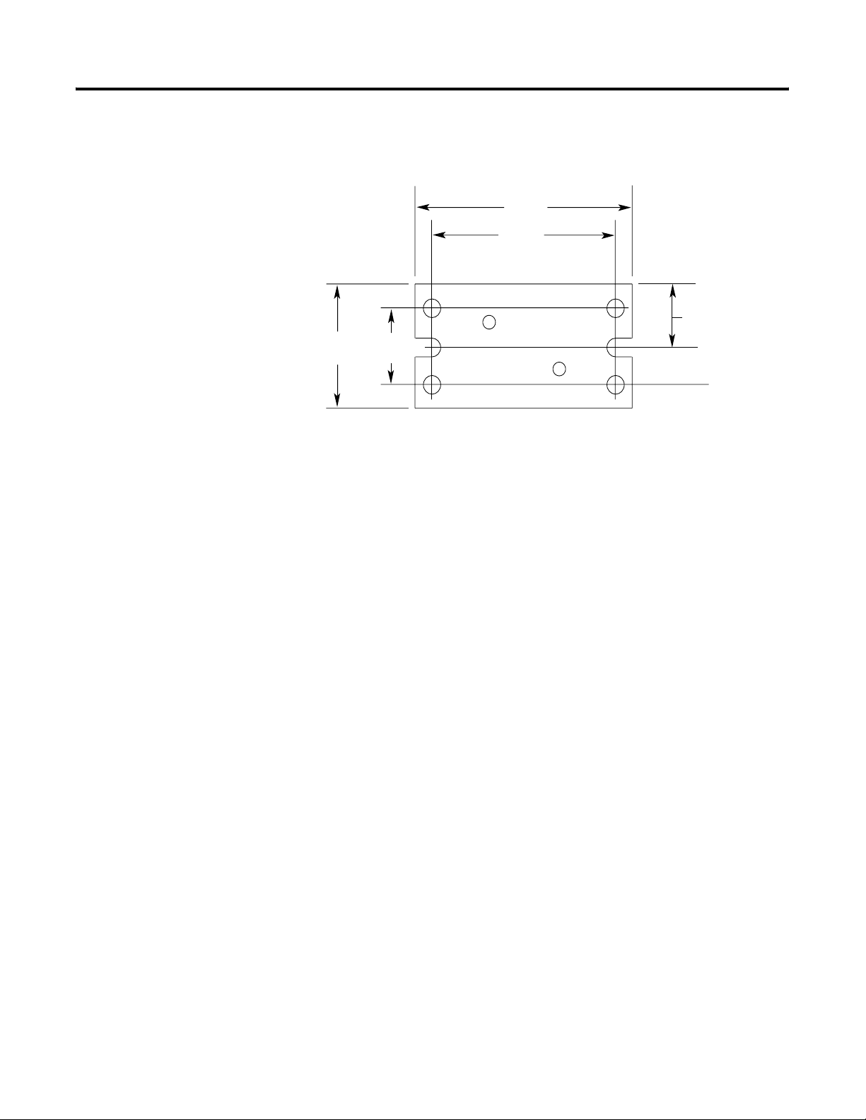
A-2 Mounting Dimensions
Universal Mounting Bracket
30.94 mm
(1.128 in.)
19.05 mm
(0.75 in.)
58.42 mm
(2.30 in.)
49.53 mm
(1.95 in.)
9.53 mm
(0.375 in.)
15.47 mm
(0.609 in.)
20170-m
Publication CNET-IN003A-EN-P - January 2006
Page 75

Adjust the Cable Strip Tool
41892
Appendix
B
What This Appendix Contains
Calibrate the Cutting Blades
Follow the instructions in this appendix to calibrate the cable strip tool
supplied with the ControlNet Coax Toolkit (1786-CTK).
Use the following procedure to calibrate your cable strip tool to cut
FEP or PVC cable.
1. Turn the three screws outward to back the blades out. This
prevents the calibration tool from bottoming out.
2. Place the calibration tool into the cable strip tool with the
narrow end installed and facing forward for FEP cable (use the
wider end for PVC).
Calibration Tool
PVC
FEP
Adjusting Screws
To Turn The Screw
Increase the cut depth Clockwise
Decrease the cut depth Counterclockwise
2088-m
3. Tighten the chamber gauge ring so that the calibration tool is
locked in place.
4. Continue tightening all the way to the chamber gauge stop.
When aligned properly, the grooves of the calibration tool
should align with the blades.
5. Adjust the screws of the memory clip so that the blades just
touch the calibration tool.
ATTENTION
1 Publication CNET-IN003A-EN-P - January 2006
Do not over-tighten the screws of the cable strip
tool. The blades should not bend, shift, or penetrate
the calibration tool.
Page 76

B-2 Adjust the Cable Strip Tool
6. Retract the handle of the cable strip tool.
7. Remove the calibration tool from the cable strip tool.
When you have finished, the blade should make a cut of the
following dimensions in your cable.
First Cut: All Four Shield
Layers-braid/tape/braid/tape
The first cut should cut the
outer sheath without cutting
the outer wire braid. If the
braid is frayed, scored, or cut
by the blade, adjust the blade
outward slightly to eliminate
the fraying.
The first and second cut adjustments need to be precise. Adjustments
as small as 1/12 to 1/8 of a turn can make the difference between a
perfect and an imperfect cut.
Second Cut: White
Insulation Or 1st Tape
The second cut should cut the
sheath, three outer shields, and
possibly the inner tape shield. The
insulation can be scored slightly,
but should not have a deep cut.
8.3 mm
(0.33 in.)
3.7 mm
4.0 mm
(0.15 in.)
(0.16 in.)
Third Cut: Center Conductor
The third cut should cut all layers
of the cable down to the center
conductor. This cut should not
score the center conductor. If the
blade leaves a mark on the
conductor, adjust the blade slightly
so to eliminate marking the
conductor.
30030-m
Publication CNET-IN003A-EN-P - January 2006
ATTENTION
Check the outer braid of cable for cut or scored braid
wire after stripping the cable. If the braid is
damaged, strip the cable again. If needed, adjust the
appropriate striper blade by backing the set screw
out 1/8 of a turn. Do not crimp the BNC to a
damaged braid. This type of mistake accounts for
most of the connectivity problems that occur.
Precise, clean connections will reduce network
errors.
Page 77

Adjust the Cable Strip Tool B-3
Reverse and Replace the Cutting Blades
To reverse or change the cutting blades:
1. Use a screwdriver to lift the memory blade holder and swing it
back.
20182-m
2. Slide the memory blade cartridge out of the strip tool.
20183-m
If You Are Go To
Reversing the memory blade cartridge
to use the second set of blades
Replacing the memory blade cartridge Step 4
The next step
3. Flip the memory blade cartridge and slide it back into the strip
tool.
Publication CNET-IN003A-EN-P - January 2006
Page 78

B-4 Adjust the Cable Strip Tool
30031-m
Go to step 5.
4. Align the memory blade cartridge (the side with the raised
notches) to the raised area on the inside of the strip tool and
slide the new memory blade cartridge in
Raised Notch
TIP
The blades should be on top as you slide the
cartridge in.
.
Raised Area
30031a-m
5. Swing the memory blade holder closed.
Publication CNET-IN003A-EN-P - January 2006
20069-m
Page 79

Adjust the Cable Strip Tool B-5
Change the Memory Blade Holder
You received two memory blade holders with your cable strip tool;
one is for PVC-CL2 cable, and the other is for plenum FEP-CL2P cable.
You need to install the appropriate memory blade holder for the type
of cable you are stripping (PVC or FEP).
1. Lift the latches on the memory blade holder and swing it back.
20182-m
2. Snap the memory blade holder off the rod and
remove it from the strip tool.
20070-m
3. Position the appropriate memory blade holder on the rod and
snap the holder into place.
4. Swing the memory blade holder closed.
20069-m
Publication CNET-IN003A-EN-P - January 2006
Page 80

B-6 Adjust the Cable Strip Tool
Notes:
Publication CNET-IN003A-EN-P - January 2006
Page 81

Appendix
C
Protect Your System Against Electrostatic
Discharge
Protect the system against electrostatic charge. Post a sign near this
module: Attention: Avoid electrostatic charge. For your convenience,
we provide some signs you can cut out below.
Post these labels or something similar beside each module to protect
the system against electrostatic charge.
Attention: Avoid electrostatic charge.
Attention: Avoid electrostatic charge.
Attention: Avoid electrostatic charge.
Attention: Avoid electrostatic charge.
1 Publication CNET-IN003A-EN-P - January 2006
Page 82

C-2 Protect Your System Against Electrostatic Discharge
Notes:
Publication CNET-IN003A-EN-P - January 2006
Page 83

Index
A
abbreviations and symbols 1-2
about this manual 1-1
application considerations 2-13
B
barrel connector 2-8
BNC cable connectors 1-6, 2-8
installing 3-13
bridge 1-2
bullet connector 2-2, 2-8
C
cable connectors 1-6, 2-8
barrel 2-8
bullet 2-8
installing 3-13
isolated bulkhead 2-8
right-angle 2-8
categories of conductors 2-13
coax cable 2-3
Collect Your Tools 3-13
continuity tester 3-19
ControlNet cable system
application considerations
cable connector
2-2
bullet
cable connectors 1-6, 2-8
optional 1-6
Coax Toolkit 3-13
component definitions 1-2
connecting cable sections 3-25
connecting devices 3-27
determine
cable needed
number of repeaters 2-8
number of taps 2-2
number of terminators needed 2-7
trunk cable section lengths 2-4
type of cable connectors needed
2-3
2-8
ferrite beads 2-15
installing
cable connectors
trunk cable 3-1
link 2-17
mounting taps 3-2
network 1-2
node 1-4
ordering components 2-17
planning guidelines 2-17
2-13
3-13
redundant media 2-10
repeater 1-2, 1-7, 2-8
segment 1-7, 2-17
stripping trunk cable 3-14
surge suppression 2-15
tap 1-2, 1-4, 2-2, 2-18
mounting dimensions A-1
terminating segments 3-25
terminator 2-18
terminators 1-3, 2-7
testing for electrical continuity 3-19,
3-24
trunk cable 1-2, 1-5, 2-18
testing 3-19, 3-24
wiring 2-14
wiring external to enclosures 2-14
wiring inside enclosures 2-14
trunk cable section 1-2, 1-5, 2-4
wiring guidelines 2-14
ControlNet Coax Toolkit
crimp tool
knife 3-17
strip gauge 3-18
strip tool 3-14
3-22
adjusting the cutting blades B-1
changing the memory blade holder
B-5
crimp tool 3-22
F
FEP cable 1-2
ferrite beads 2-15
flare tool 3-13
I
installing cable connectors
stripping the cable
stripping trunk cable 3-14
isolated bulkhead connector 2-8
3-17
L
link
planning
2-17
M
media
redundant
mounting dimensions
tap
2-10
guidelines 2-10
A-1
Publication CNET-IN003A-EN-P - January 2006
Page 84

2 Index
N
NetLinx Media Checker 3-19
node 1-4
O
ohmmeter 3-19
ordering components 2-17
P
programming terminals
ways to connect to a ControlNet link
publications
1770-4.1
AG-PA002 1-4, 2-8
CNET-IN001 1-1
CNET-IN002 1-1
PVC cable 1-2, 3-1, 3-17
2-14
R
redundant media 2-10
guidelines 2-10
repeater 1-2, 1-7, 2-8
selecting where to mount 3-8
RG-6 cable 2-3, 3-1
right-angle connector 2-8
2-3
changing the memory blade holder B-5
support
questions or comments about manual
1-2
technical product assistance 1-2
surge suppression 2-15
T
tap 1-2, 1-4, 2-18
determine number needed 2-2
mounting 3-2
to a universal mounting bracket 3-4
using the body holes 3-6
mounting dimensions A-1
selecting where to mount 3-2
techniques used in the manual 1-2
terminators 1-3, 2-7
trunk cable 1-2, 1-5
bend radius 3-1
installing 3-1
pull strength 3-1
stripping 3-14
terminating 3-25
testing for shorts and continuity 3-19,
3-24
wiring external to enclosures 2-14, 3-1
wiring inside enclosures 2-14, 3-2
trunk cable section 1-2, 1-5, 2-4, 3-25
S
segment 1-7
planning 2-17
terminating 3-25
strip tool
adjusting the cutting blades
B-1
W
wiring
external to enclosures
inside enclosures 2-14, 3-2
wiring guidelines 2-14
2-14, 3-1
Publication CNET-IN003A-EN-P - January 2006
Page 85

How Are We Doing?
Your comments on our technical publications will help us serve you better in the future.
Thank you for taking the time to provide us feedback.
You can complete this form and mail (or fax) it back to us or email us at
RADocumentComments@ra.rockwell.com
Pub. Title/Type ControlNet Ex Media Planning and Installation Manual
Cat. No.
1797-series Pub. No. CNET-IN003A-EN-P Pub. Date January 2006 Part No. 957208-04
Please complete the sections below. Where applicable, rank the feature (1=needs improvement, 2=satisfactory, and 3=outstanding).
Overall Usefulness 1 2 3 How can we make this publication more useful for you?
Completeness
(all necessary information
is provided)
Technical Accuracy
(all provided information
is correct)
1 2 3 Can we add more information to help you?
procedure/step illustration feature
example guideline other
explanation definition
1 2 3 Can we be more accurate?
t ex t i ll u st r at i o n
Clarity
(all provided information is
easy to understand)
Other Comments You can add additional comments on the back of this form.
Your Name
Your Title/Function Would you like us to contact you regarding your comments?
Location/Phone
Return this form to: Rockwell Automation Technical Communications, 1 Allen-Bradley Dr., Mayfield Hts., OH 44124-9705
Publication CIG-CO521C-EN-P- May 2003 PN957208-04957782-91
1 2 3 How can we make things clearer?
___No, there is no need to contact me
___Yes, please call me
___Yes, please email me at _______________________
___Yes, please contact me via _____________________
Fax: 440-646-3525 Email: RADocumentComments@ra.rockwell.com
Page 86

Other Comments
PLEASE FASTEN HERE (DO NOT STAPLE)
PLEASE FOLD HERE
BUSINESS REPLY MAIL
FIRST-CLASS MAIL PERMIT NO. 18235 CLEVELAND OH
POSTAGE WILL BE PAID BY THE ADDRESSEE
NO POSTAGE
NECESSARY
IF MAILED
IN THE
UNITED STATES
PLEASE REMOVE
1 ALLEN-BRADLEY DR
MAYFIELD HEIGHTS OH 44124-9705
Page 87

Page 88

Rockwell Automation
Support
Rockwell Automation provides technical information on the web to assist you
in using our products. At http://support.rockwellautomation.com, you can
find technical manuals, a knowledge base of FAQs, technical and application
notes, sample code and links to software service packs, and a MySupport
feature that you can customize to make the best use of these tools.
For an additional level of technical phone support for installation,
configuration and troubleshooting, we offer TechConnect Support programs.
For more information, contact your local distributor or Rockwell Automation
representative, or visit http://support.rockwellautomation.com.
Installation Assistance
If you experience a problem with a hardware module within the first 24
hours of installation, please review the information that's contained in this
manual. You can also contact a special Customer Support number for initial
help in getting your module up and running:
United States 1.440.646.3223
Monday – Friday, 8am – 5pm EST
Outside United
States
Please contact your local Rockwell Automation representative for any
technical support issues.
New Product Satisfaction Return
Rockwell tests all of our products to ensure that they are fully operational
when shipped from the manufacturing facility. However, if your product is
not functioning and needs to be returned:
United States Contact your distributor. You must provide a Customer Support case
number (see phone number above to obtain one) to your distributor in
order to complete the return process.
Outside United
States
Please contact your local Rockwell Automation representative for
return procedure.
Publication CNET-IN003A-EN-P - January 2006 5 PN 957208-04
Copyright © 2006 Rockwell Automation, Inc . All rights reserved. Printed in the U.S.A.
 Loading...