

Page 1

User Manual
1794 FLEX I/O Very High Speed Counter Module
Catalog Numbers
1794-VHSC
Page 2
Important User Information
IMPORTANT
Solid-state equipment has operational characteristics differing from those of electromechanical equipment. Safety
Guidelines for the Application, Installation and Maintenance of Solid State Controls (publication SGI-1.1
your local Rockwell Automation sales office or online at http://www.rockwellautomation.com/literature/
important differences between solid-state equipment and hard-wired electromechanical devices. Because of this difference,
and also because of the wide variety of uses for solid-state equipment, all persons responsible for applying this equipment
must satisfy themselves that each intended application of this equipment is acceptable.
In no event will Rockwell Automation, Inc. be responsible or liable for indirect or consequential damages resulting from
the use or application of this equipment.
The examples and diagrams in this manual are included solely for illustrative purposes. Because of the many variables and
requirements associated with any particular installation, Rockwell Automation, Inc. cannot assume responsibility or
liability for actual use based on the examples and diagrams.
No patent liability is assumed by Rockwell Automation, Inc. with respect to use of information, circuits, equipment, or
software described in this manual.
Reproduction of the contents of this manual, in whole or in part, without written permission of Rockwell Automation,
Inc., is prohibited.
Throughout this manual, when necessary, we use notes to make you aware of safety considerations.
WARNING: Identifies information about practices or circumstances that can cause an explosion in a hazardous
environment, which may lead to personal injury or death, property damage, or economic loss.
available from
) describes some
ATTENTION: Identifies information about practices or circumstances that can lead to personal injury or death,
property damage, or economic loss. Attentions help you identify a hazard, avoid a hazard, and recognize the
consequence
SHOCK HAZARD: Labels may be on or inside the equipment, for example, a drive or motor, to alert people that
dangerous voltage may be present.
BURN HAZARD: Labels may be on or inside the equipment, for example, a drive or motor, to alert people that
surfaces may reach dangerous temperatures.
Identifies information that is critical for successful application and understanding of the product.
Allen-Bradley, Rockwell Automation, FLEX I/O, ControlLogix, RSlogix, R SLinx, and TechConnect are trademarks of Rockwell Automation, Inc.
Trademarks not belonging to Rockwell Automation are property of their respective companies.
Page 3

Summary of Changes
This manual contains new and updated information. Changes throughout this
revision are marked by change bars, as shown to the right of this paragraph.
New and Updated Information
This table contains the major changes and additions made to this revision.
Topic Page
Updated Frequency Resolution/Enhancement section. 33
Updated Word 8 Bit/Word Definitions. 39, 40
Rockwell Automation Publication 1794-UM010D-EN-E - July 2013 iii
Page 4

Summary of Changes
Notes:
iv Rockwell Automation Publication 1794-UM010D-EN-E - July 2013
Page 5
Preface
Read this preface to familiarize yourself with the rest of the manual. It provides
information concerning:
• who should use this manual
• the purpose of this manual
• related documentation
Who Should Use this Manual
Purpose of this Manual
You must be able to program and operate an Allen-Bradley programmable
controller (PLC) to make efficient use of this module.
We assume that you know how to do this in this manual. If you do not, refer to
the appropriate programming and operations manual for the associated
programmable controller before you attempt to use this module.
This manual shows you how to use the FLEX I/O Very High Speed Counter
module with an Allen-Bradley programmable controller. It helps you install,
program, and troubleshoot your module.
For Information About See Page
Overview of the Very High Speed Counter Module 1
Install Your FLEX I/O VHSC Module 17
Programming Your Very High Speed Counter Module 55
Communicate With Your Module 29
Interpret Status Indicators for your FLEX I/O Module 47
Specifications 49
Additional Resources
These documents contain additional information concerning related Rockwell
Automation products.
Resource Description
FLEX I/O Selection Guide, publication 1794-SG002
Very High Speed Counter Module Installation Instructions,
publication 1794-IN067
ControlLogix System User Manual, publiation 1756-UM001
EtherNet/IP Modules Installation Instructions,
publication ENET-IN002
FLEX I/O DC Power Supply Installation Instructions,
publication 1794-IN069
EtherNet/IP Modules in Logix5000 Control Systems User Manual,
publication ENET-UM001
Rockwell Automation Publication 1794-UM010D-EN-E - July 2013 v
A description and overview of the 1794 series FLEX I/O, FLEX I/O XT and FLEX Ex
modules and compatible control platforms.
Information on installing the FLEX I/O Very High Speed Counter Module.
Detailed information on how to install, configure and troubleshoot the ControlLogix
module in your ControlLogix application.
Information on installing EtherNet/IP bridge modules.
Information on how to install the FLEX I/O DC Power Supply Catalog No. 1794-PS13,
1794-PS3.
Detailed information on how to use EtherNet/IP modules with Logix5000 controllers
and communicate with various devices on the Ethernet network.
Page 6

Preface
Resource Description
Industrial Automation Wiring and Grounding Guidelines,
publication 1770-IN041
Product Certifications website, http://ab.com Provides declarations of conformity, certificates, and other certification details.
Application Considerations for Solid-State Controls,
publication SGI-1.1
Allen-Bradley Industrial Automation Glossary, publication AG-7.1
Provides general guidelines for installing a Rockwell Automation industrial system.
A description of important differences between solid-state programmable controller
products and hard-wired electromechanical devices.
A glossary of industrial automation terms and abbreviations.
You can view or download publications at
http://www.rockwellautomation.com/literature/
. To order paper copies of
technical documentation, contact your local Rockwell Automation distributor or
sales representative.
Common Techniques Used in this Manual
The following conventions are used throughout this manual:
• Bulleted lists such as this one provide information, not procedural steps.
• Numbered lists provide sequential steps or hierarchical information.
• Italic type is used for emphasis.
vi Rockwell Automation Publication 1794-UM010D-EN-E - July 2013
Page 7

Table of Contents
Summary of Changes
Preface
Overview of the Very High
Speed Counter Module
New and Updated Information. . . . . . . . . . . . . . . . . . . . . . . . . . . . . . . . . . . . . iii
Who Should Use this Manual . . . . . . . . . . . . . . . . . . . . . . . . . . . . . . . . . . . . . . . v
Purpose of this Manual . . . . . . . . . . . . . . . . . . . . . . . . . . . . . . . . . . . . . . . . . . . . . v
Additional Resources . . . . . . . . . . . . . . . . . . . . . . . . . . . . . . . . . . . . . . . . . . . . . . . v
Common Techniques Used in this Manual . . . . . . . . . . . . . . . . . . . . . . . . . . vi
Chapter 1
Overview . . . . . . . . . . . . . . . . . . . . . . . . . . . . . . . . . . . . . . . . . . . . . . . . . . . . . . . . . 1
Module Description . . . . . . . . . . . . . . . . . . . . . . . . . . . . . . . . . . . . . . . . . . . . . . . 1
Module Features. . . . . . . . . . . . . . . . . . . . . . . . . . . . . . . . . . . . . . . . . . . . . . . 1
Encoder or Counter Mode . . . . . . . . . . . . . . . . . . . . . . . . . . . . . . . . . . . . . . . . . 2
Counter Mode . . . . . . . . . . . . . . . . . . . . . . . . . . . . . . . . . . . . . . . . . . . . . . . . 3
Encoder Mode . . . . . . . . . . . . . . . . . . . . . . . . . . . . . . . . . . . . . . . . . . . . . . . . 4
Direction of Count . . . . . . . . . . . . . . . . . . . . . . . . . . . . . . . . . . . . . . . . . . . . 5
Preset Value . . . . . . . . . . . . . . . . . . . . . . . . . . . . . . . . . . . . . . . . . . . . . . . . . . . 6
Rollover Value. . . . . . . . . . . . . . . . . . . . . . . . . . . . . . . . . . . . . . . . . . . . . . . . . 6
Software Reset. . . . . . . . . . . . . . . . . . . . . . . . . . . . . . . . . . . . . . . . . . . . . . . . . 6
Gate/Reset Input . . . . . . . . . . . . . . . . . . . . . . . . . . . . . . . . . . . . . . . . . . . . . . 6
Period/Rate Mode. . . . . . . . . . . . . . . . . . . . . . . . . . . . . . . . . . . . . . . . . . . . . . . . . 8
Operation of Scaler . . . . . . . . . . . . . . . . . . . . . . . . . . . . . . . . . . . . . . .10
Connection to Counter Inputs. . . . . . . . . . . . . . . . . . . . . . . . . . . . .10
Continuous/Rate Mode . . . . . . . . . . . . . . . . . . . . . . . . . . . . . . . . . . . . . . . . . . 10
Rate Measurement Mode . . . . . . . . . . . . . . . . . . . . . . . . . . . . . . . . . . . . . . . . . 11
Sample Period . . . . . . . . . . . . . . . . . . . . . . . . . . . . . . . . . . . . . . . . . . . .12
Connection to Counter Inputs. . . . . . . . . . . . . . . . . . . . . . . . . . . . .12
Pulse Width Modulation. . . . . . . . . . . . . . . . . . . . . . . . . . . . . . . . . . . . . . . . . . 12
Outputs . . . . . . . . . . . . . . . . . . . . . . . . . . . . . . . . . . . . . . . . . . . . . . . . . . . . . . . . . 13
Enabling and Forcing Outputs. . . . . . . . . . . . . . . . . . . . . . . . . . . . . . . . . 13
Assigning Outputs to Counter Windows . . . . . . . . . . . . . . . . . . . . . . . 13
Operation of Outputs . . . . . . . . . . . . . . . . . . . . . . . . . . . . . . . . . . . . .13
Isolation of Outputs . . . . . . . . . . . . . . . . . . . . . . . . . . . . . . . . . . . . . .14
Connecting Outputs to Counters . . . . . . . . . . . . . . . . . . . . . . . . . .14
What the Module Does . . . . . . . . . . . . . . . . . . . . . . . . . . . . . . . . . . . . . . . . . . . 14
Chapter Summary. . . . . . . . . . . . . . . . . . . . . . . . . . . . . . . . . . . . . . . . . . . . . . . . 15
Chapter 2
Install Your FLEX I/O VHSC
Module
Rockwell Automation Publication 1794-UM010D-EN-E - July 2013 vii
Overview . . . . . . . . . . . . . . . . . . . . . . . . . . . . . . . . . . . . . . . . . . . . . . . . . . . . . . . . 17
Before You Install Your Module . . . . . . . . . . . . . . . . . . . . . . . . . . . . . . . . . . . 17
Power Requirements . . . . . . . . . . . . . . . . . . . . . . . . . . . . . . . . . . . . . . . . . . 17
Install the Module. . . . . . . . . . . . . . . . . . . . . . . . . . . . . . . . . . . . . . . . . . . . . . . . 17
Mount on a DIN Rail . . . . . . . . . . . . . . . . . . . . . . . . . . . . . . . . . . . . . . . . . 18
Install the Terminal Base Unit . . . . . . . . . . . . . . . . . . . . . . . . . . . . .18
Mount on a Panel or Wall . . . . . . . . . . . . . . . . . . . . . . . . . . . . . . . . . . . . . 20
Page 8

Mount the 1794-VHSC Module on the Terminal Base Unit . . . . . 21
Wiring Information . . . . . . . . . . . . . . . . . . . . . . . . . . . . . . . . . . . . . . . . . . . . . . 23
Connect Wiring to the FLEX I/O VHSC Input Module . . . . . . . . 24
Connect Wiring Using a 1794-TB3G, 1794-TB3GK or 1794-TB3GS
Terminal Base Unit . . . . . . . . . . . . . . . . . . . . . . . . . . . . . . . . . . . . . . . . . . . 24
Chapter Summary. . . . . . . . . . . . . . . . . . . . . . . . . . . . . . . . . . . . . . . . . . . . . . . . 28
Chapter 3
Communicate With Your
Module
Interpret Status Indicators for
your FLEX I/O Module
Overview . . . . . . . . . . . . . . . . . . . . . . . . . . . . . . . . . . . . . . . . . . . . . . . . . . . . . . . . 29
Communication Over the
I/O Backplane . . . . . . . . . . . . . . . . . . . . . . . . . . . . . . . . . . . . . . . . . . . . . . . . . . . 29
Scheduled Data-Transfer . . . . . . . . . . . . . . . . . . . . . . . . . . . . . . . . . . . . . . 30
Unscheduled Data-Transfer . . . . . . . . . . . . . . . . . . . . . . . . . . . . . . . . . . . 30
Module I/O Mapping. . . . . . . . . . . . . . . . . . . . . . . . . . . . . . . . . . . . . . . . . 30
Application of New Configurations . . . . . . . . . . . . . . . . . . . . . . . . . . . . 30
I/O Structure . . . . . . . . . . . . . . . . . . . . . . . . . . . . . . . . . . . . . . . . . . . . . . . . . . . . 31
Adapter Input Status Word . . . . . . . . . . . . . . . . . . . . . . . . . . . . . . . . . . . 31
Safe State Data . . . . . . . . . . . . . . . . . . . . . . . . . . . . . . . . . . . . . . . . . . . . . . . . . . . 32
Device Actions . . . . . . . . . . . . . . . . . . . . . . . . . . . . . . . . . . . . . . . . . . . . . . . . . . . 32
Communication Fault Behavior . . . . . . . . . . . . . . . . . . . . . . . . . . . . . . . 33
Idle State Behavior. . . . . . . . . . . . . . . . . . . . . . . . . . . . . . . . . . . . . . . . . . . . 33
Input Data Behavior upon Module Removal . . . . . . . . . . . . . . . . . . . . 33
Frequency/Resolution Enhancement. . . . . . . . . . . . . . . . . . . . . . . . . . . 33
Chapter Summary. . . . . . . . . . . . . . . . . . . . . . . . . . . . . . . . . . . . . . . . . . . . . . . . 45
Chapter 4
Overview . . . . . . . . . . . . . . . . . . . . . . . . . . . . . . . . . . . . . . . . . . . . . . . . . . . . . . . . 47
Status Indicators . . . . . . . . . . . . . . . . . . . . . . . . . . . . . . . . . . . . . . . . . . . . . . . . . 47
Diagnostic Codes Returned by the Module . . . . . . . . . . . . . . . . . . . . . . . . . 48
Chapter Summary. . . . . . . . . . . . . . . . . . . . . . . . . . . . . . . . . . . . . . . . . . . . . . . . 49
Appendix A
Specifications
Programming Your Very High
Speed Counter Module
Index
viii Rockwell Automation Publication 1794-UM010D-EN-E - July 2013
Overview . . . . . . . . . . . . . . . . . . . . . . . . . . . . . . . . . . . . . . . . . . . . . . . . . . . . . . . . 51
Appendix B
. . . . . . . . . . . . . . . . . . . . . . . . . . . . . . . . . . . . . . . . . . . . . . . . . . . . . . . . . . . . . . . . . 55
. . . . . . . . . . . . . . . . . . . . . . . . . . . . . . . . . . . . . . . . . . . . . . . . . . . . . . . . . . . . . . . . . 57
Page 9

Overview of the Very High Speed
IMPORTANT
Counter Module
Chapter
1
Overview
Module Description
This chapter gives you information on features of the modules, how the module
communicates with controllers and how the module operates.
Topic Page
Module Description
Encoder or Counter Mode 2
Period/Rate Mode 8
Continuous/Rate Mode 10
Rate Measurement Mode 11
Pulse Width Modulation 12
Outputs 13
What the Module Does 14
The 1794-VHSC module performs high speed counting for industrial
applications. The module is an intelligent I/O module that interfaces signals with
any Allen-Bradley programmable controller that has Ethernet capability.
The 1794-VHSC module, once configured for its intended purpose, can
continue to operate without FlexBus power.
1
Customer power is required for the module, inputs and outputs.
After scanning the inputs and updating the outputs, the input data is converted to
a specified data type in a digital format to be transferred to the processor’s data
table on request. Command and configuration data is sent from the
programmable controller data tables to the module via Ethernet.
Module Features
The 1794-VHSC module counts pulses from encoders (such as Allen-Bradley
Bulletin 845), pulse generators or mechanical limit switches, or proximity
switches, and returns either a count or frequency in binary format.
Rockwell Automation Publication 1794-UM010D-EN-E - July 2013 1
Page 10

Overview of the Very High Speed Counter Module
The module features include:
• 2 counters configurable for 3 encoder modes, counter mode, period/rate
mode, continuous/rate mode, rate measurement and pulse width
modulation (PWM)
• 4 outputs, isolated in pairs
• outputs are current-sourcing at 5 or 12…24V DC (0.5 mA max @ 5V; 1 A
max @ 12…24V)
• single-ended or differential inputs
• 2-phase encoder inputs up to a frequency of 250 KHz (X 4 mode)
• single-phase counter inputs up to a frequency of 1 MHz
• input voltage range of 5 or 24V DC
• returns input as count or frequency in binary format
• input counts as high as 16,777,215
• up to 1 MHz in period/rate or rate measurement frequency modes
• outputs can be tied to any or all counter windows
• each output has a user-selectable on-off value
• outputs can be tied back to an input for cascading
• each counter has a user-selectable preset and rollover value
• totalization is provided in period/rate, continuous/rate and rate
measurement modes
• module can continue counting without flexbus power (after configuration)
• outputs have safe state values which can be applied when there is a network
failure or the PLC is switched to PROGRAM mode
• pulse width modulation (PWM) mode is available
The 1794-VHSC module operates in the following modes:
• counter mode
• encoder X1 mode
• encoder X2 mode
• encoder X4 mode
• period/rate mode
• continuous/rate mode
• rate measurement frequency mode
• pulse width modulation (PWM)
Encoder or Counter Mode
2 Rockwell Automation Publication 1794-UM010D-EN-E - July 2013
The operation of encoder and counter modes is virtually identical. The only
difference between the two modes is in the type of feedback used.
Use the counter mode if you need the module to read incoming pulses from a
maximum of 2 encoders (single-ended or differential), counters, pulse generators,
mechanical limit switches, etc. and return them to the programmable controller
as a binary number (0…16,777,215).
Page 11

Overview of the Very High Speed Counter Module
Use the encoder modes if you need the module to read incoming quadrature
pulses and return them to the programmable controller as a binary number
(0…16,777,215). In these modes, the module accepts two-phase quadrature
feedback and counts up or down depending upon the condition of the phase B
input for each counter.
The operation of the module in the encoder/counter modes is as follows:
• counter mode – channel B is direction control (up or down). Channel A
input is used for pulse. The count is bidirectional with the direction
determined by channel B.
• encoder X1 – This is a bidirectional count mode; counting up or down,
using quadrature input signals.
• encoder X2 – This is a bidirectional count mode, using quadrature input
signals, with 2 times the resolution of X1.
• encoder X4 – This is a bidirectional count mode, using quadrature input
signals, with 4 times the resolution of X1.
Each of the counters in encoder/counter mode has values associated with it.
These are:
• preset value
• rollover value
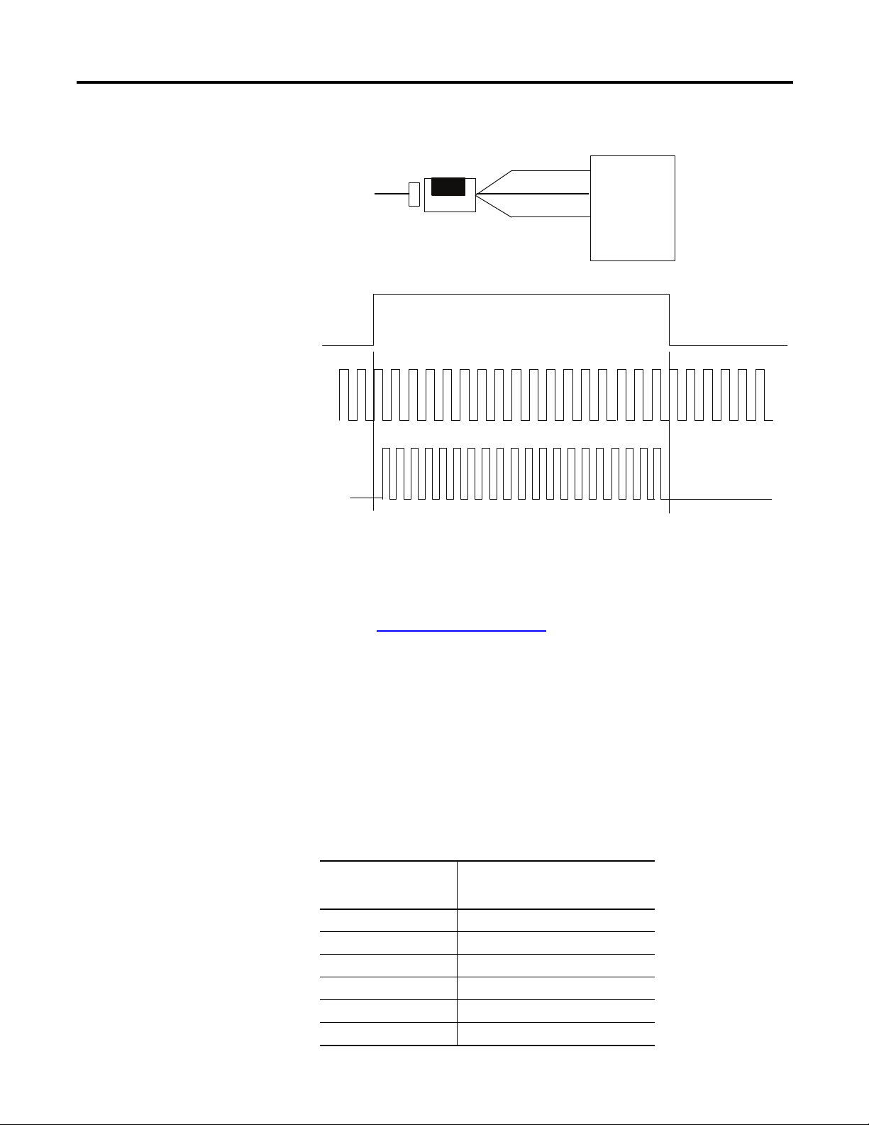
Counter Mode
The counter mode allows the module to read incoming pulses and return them to
the programmable controller processor as a binary number (0…16,777,215).
In the counter mode, direction (up counting or down counting ) is determined by
the phase B input, which can be a random signal. If Phase B is high, the counter
will count down. If phase B is low or floating, (that is, not connected), the
counter counts up.
Counter Mode Direction
Phase B Input Count direction
High Down
Low or floating (not included) Up
The module reads incoming pulses from a maximum of 2 encoders (single-ended
or differential), counters, pulse generators, mechanical limit switches, and so
forth and returns a count to the programmable controller processor in a binary
number (0-16,777,215).
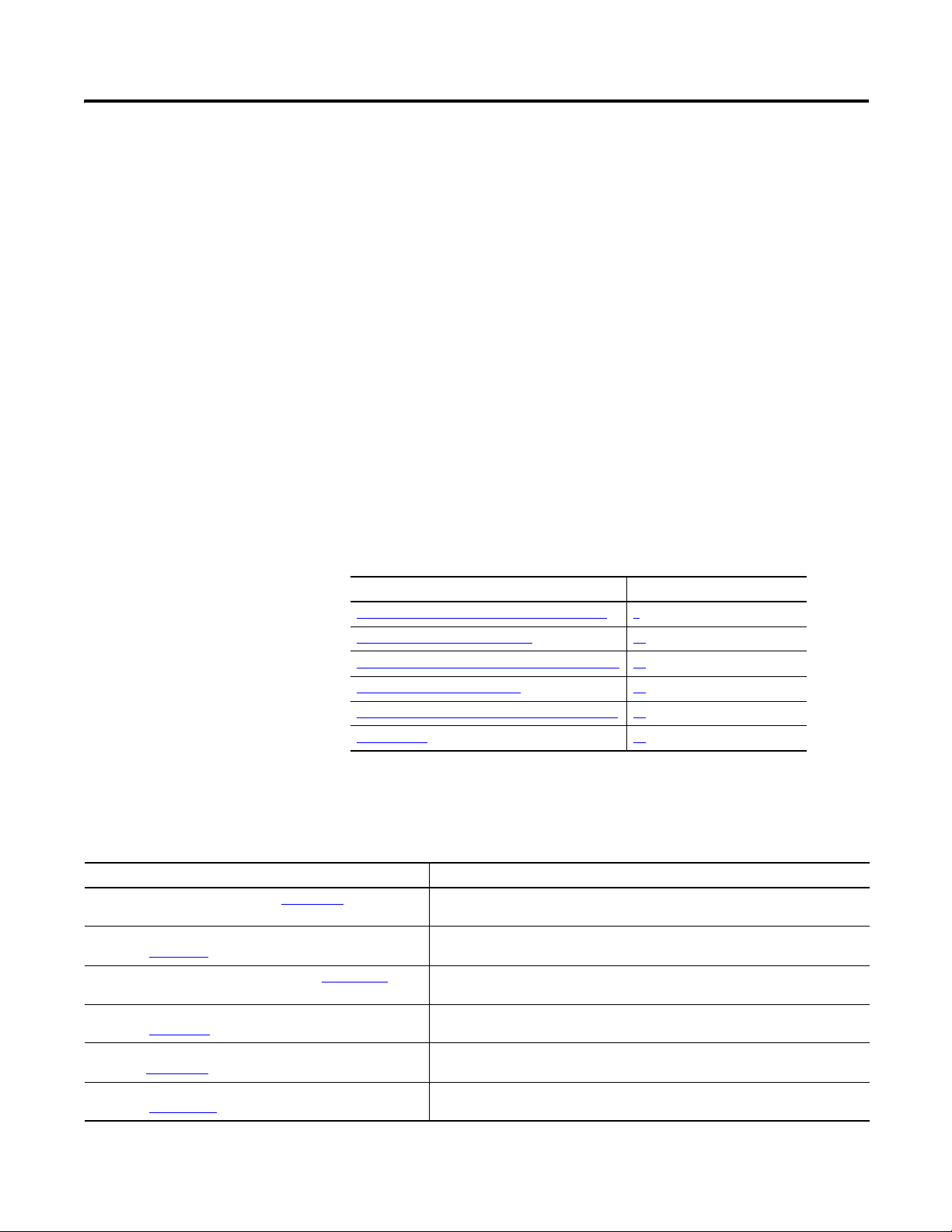
The counter mode accepts only one phase feedback. This relationship is shown in
Figure Block Diagram of Counter Mode
on page 4.
Rockwell Automation Publication 1794-UM010D-EN-E - July 2013 3
Page 12
Overview of the Very High Speed Counter Module
A
B
01 2 3 2 1 0
Input A
Input B
Z(Store count)
Single phase pulse generator
1794-VHSC
Input Z
(Gate/Reset)
Count down
A input
B input
Count
Count up
+
-
Outputs updated continuously
45891
Block Diagram of Counter Mode
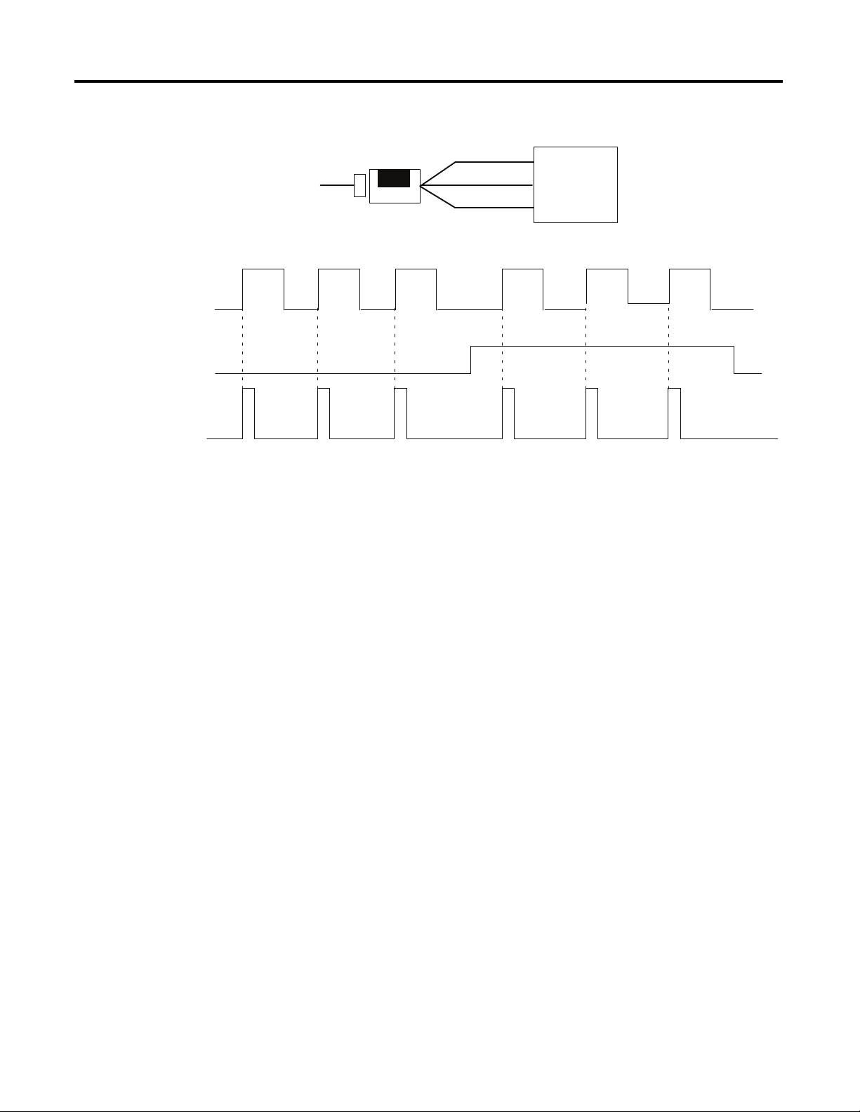
Encoder Mode
The encoder mode allows the module to read incoming pulses and return them to
the programmable controller processor as a binary number (0-16,777,215).
In this mode, the module will accept two phase quadrature feedback. The module
senses the relationship between the 2 phases and counts up or down accordingly.
Encoder X1 mode – quadrature input signals count on the leading edge or the
trailing edge of channel A for a bidirectional count. The phase relationship
between Channel A and Channel B determines direction — channel A leading,
and channel B floating, the count direction is up; Channel A lagging, and
Channel B high, the count direction is down.
Encoder X2 mode – quadrature input signals count on the leading edge and the
trailing edge of channel A for a bidirectional count. Channel B determines
direction —B low (floating), the count direction is up; B high, the count
direction is down.
Encoder X4 mode – quadrature input signals count on the leading edge and the
trailing edge of channel A and channel B for a bidirectional count. Channel B
determines direction — B low (floating), the count direction is up; B high, the
count direction is down.
4 Rockwell Automation Publication 1794-UM010D-EN-E - July 2013
Page 13
Overview of the Very High Speed Counter Module
A input
B input
X1
count
A
B
Input A
Input B
Reverse rotation
CW encoder rotation
Forward rotation
CCW encoder rotation
120
312
1 2 3 4 5 6 7 8 9 10 11 1 2
1234567
8
9101112
0
1 2 3 4 5 6 7 8 9 10 11 1 2
1234567
8
9101112
0
Z(Store count)
Quadrature encoder
1794-VHSC
Input Z
(Gate/Reset)
45892
Direction of Count
The module can count either up or down, depending upon the condition of the B
input for each counter. In encoder applications, the counter will increment on the
leading edge of input A, while input B determines the direction of the count.
You also have the option of X1, X2 and X4 multiplying of the input pulses. See
Figure Phase Relationship for Forward or Reverse Directions
relationships between inputs A and B for forward and reverse directions in
encoder applications.
Phase Relationship for Forward or Reverse Directions
on page 5 for the
The following paragraphs apply to both encoders and counters.
Rockwell Automation Publication 1794-UM010D-EN-E - July 2013 5
Page 14

Overview of the Very High Speed Counter Module
Preset Value
Each of the 2 counters has one preset value associated with it. In the encoder or
counter modes, the preset value represents a reference point (or count) from
which the module begins counting. The module can count either up or down
from the preset value. Preset values are loaded into the count registers through the
preset count bits. Preset values can range from 0 to 16,777,215 binary.
Rollover Value
Each of the 2 counters has one rollover value associated with it. When the
rollover value is reached by the encoder/counter, it resets to 0 and begins
counting again. The rollover values range from 1 to 16,777,216 binary. The
rollover value is circular. For example: if you program 360, the count will be from
358, 359, 0, 1, and so on, in a positive direction and from 1, 0, 359, 358, and so
on, in a negative direction.
Software Reset
The counters can also be reset by the Reset Count bits found in Word 0, bits 0
and 4 of the Counter Control word. When one of these bits is set to 1, the
associated counter is reset to zero and begins counting. The module can also be
reset with the gate/reset as explained below. For more details, .
Gate/Reset Input
There is one gate/reset input for each of the 2 counters. The gate/reset input,
when active, will function in one of the 4 store count modes outlined below.
Scaling Input Count at the Gate/Reset Terminal
You can scale the incoming count at the gate/reset terminal. Scaling allows the
incoming pulses at gate/reset to be divided by a number in the range of 1, 2, 4, 8,
16, 32, 64 and 128.
Store Count
The store count feature allows the module to store the current count value of the
associated counter. The store count feature is triggered by the state of the gate/
reset terminal on the module. The stored count of each counter is placed in a
separate word in the Read Data file. The stored count value will remain in the
Read Data file until a new trigger pulse is received at the Gate/Reset terminal.
When a new trigger pulse is received, the old count value will be overwritten by
the new value.
In mode 1, store/continue (see Figure Store/Continue
edge of a pulse input on input Z (gate/reset) terminal causes the current value in
6 Rockwell Automation Publication 1794-UM010D-EN-E - July 2013
on page 7), the leading
Page 15

Overview of the Very High Speed Counter Module
Read, Store Count and
continue counting.
Store Count
Stop counting
Resume counting
Stop count, store
and reset to zero
Counter has stopped counting
Start counting
from zero
the counter to be read and stored. The counter will continue counting. The
stored count will be available in the Read Data file. The stored count information
will remain in the block transfer read file until it is overwritten by new data.
Store/Continue
In mode 2, store/wait/resume (see Figure Store/Wait/Resume on page 7), a rising
edge of a pulse input on the Z input (gate/reset) terminal reads and stores the
current counter value in the Read Data file, and inhibits counting while the gate/
reset input is high. Counting resumes when the input goes low.
Mode 2 does not reset the counter, although it does store the count value. The
stored count is available in the Read Data file. The stored count remains in the
Read Data file until it is overwritten with new data.
Store/Wait/Resume
In mode 3, store-reset/wait/start (see Figure Store-Reset/Wait/Start on page 7),
the rising edge of the pulse on input Z (gate/reset) terminal causes the counter to
stop counting, store the current count value in the Read Data file and reset the
count to zero. The counter does not count while the Z input on the gate/reset
terminal remains high. Counting resumes from zero on the falling edge of the
pulse at the Z (gate/reset) terminal. The stored count is available in the Read
Data file. The stored count remains in the Read Data file until it is overwritten
with new data.
Store-Reset/Wait/Start
In mode 4, store-reset/start (see Figure Store-Reset/Start on page 8), on the rising
edge of a pulse input at the Z (gate/reset) terminal causes the counter to store the
accumulated count value in the Read Data file, and reset the counter to zero. The
counter continues counting while the Z gate/reset input is high. The stored count
Rockwell Automation Publication 1794-UM010D-EN-E - July 2013 7
Page 16

Overview of the Very High Speed Counter Module
Store Count,
reset to zero,
start counting
Rising edge
Store Count,
reset to zero,
start counting
Falling edge
is available in the Read Data file. The stored count remains in the Read Data file
until it is overwritten with new data.
Store-Reset/Start
The figures show the store count feature operating on the rising edge of the gate/
reset pulse. The user has the option of electing these same features using the
falling edge of the gate/reset pulse. The gate invert bit is active in the store count,
continuous/rate and period/rate modes.
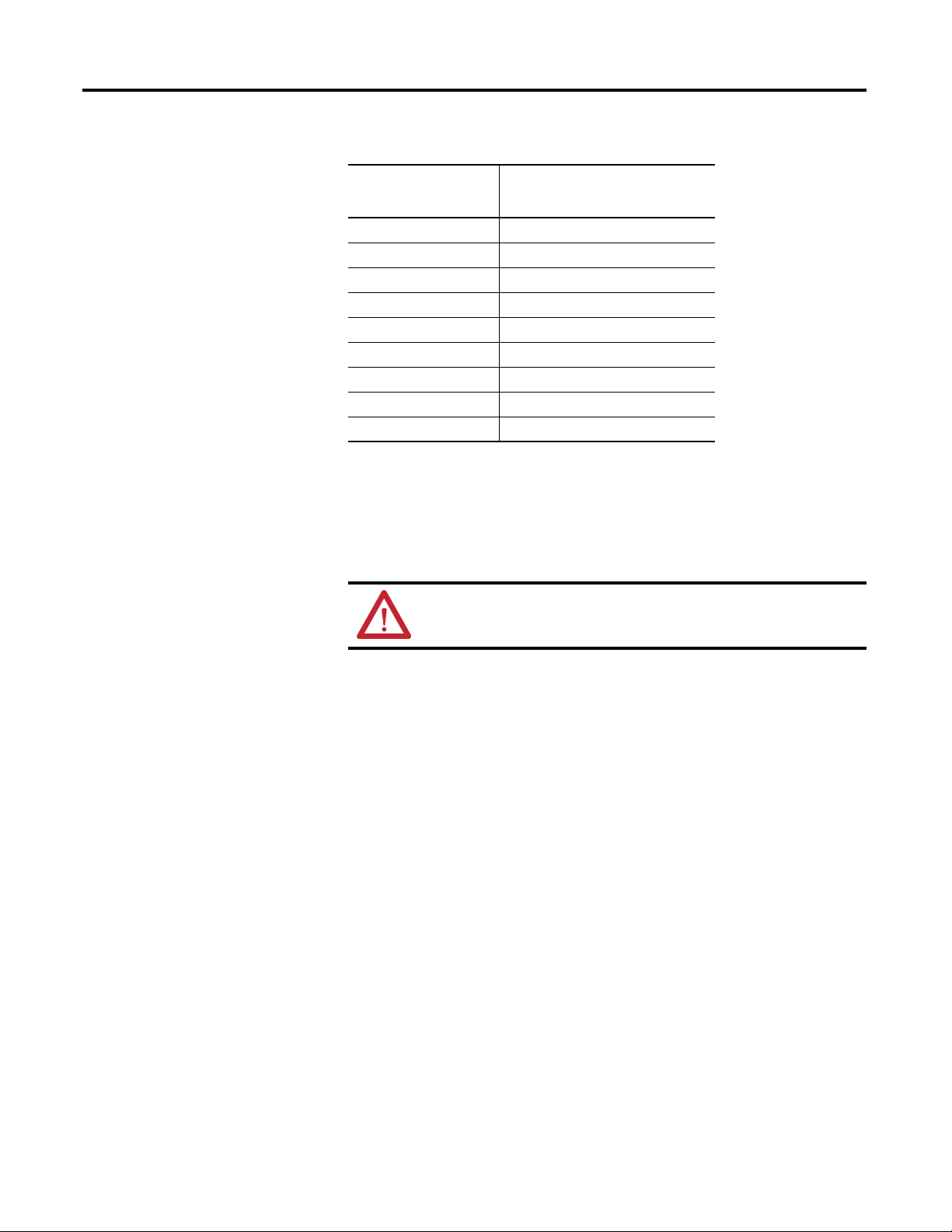
Period/Rate Mode
Use the period/rate mode to determine the frequency of input pulses by counting
the number of internal 5MHz clock pulses over a user-specified number of input
signal pulses. At the end of the specified number of pulses, the module returns the
frequency and the total number of pulses received.
A channel configured for period/rate mode acts as a period rate counter. An
internal 5MHz clock is used as a frequency reference. This clock is gated by the
incoming pulse train at the gate/reset input. The results of this gating action are
the number of pulses or a frequency. The frequency is returned in input file words
0 (LSW) and 1 (MSW) for channel 0 and word 2 (LSW) and 3 (MSW) for
channel 1. The total pulses received is stored in input file words 4 (LSW) and 5
(MSW) for channel 0 and words 6 (LSW) and 7 (MSW) for channel 1. Select
the period/rate mode by setting the appropriate bits in word 0 of the
configuration block.
1794-VHSC modules count the total number of pulses occurring at the Z (gate/
reset) pin. This function is frequency-limited to 200Hz X the scaler value. You
can reset this count by setting the VR bit.
Figure Period/Rate Mode
on page 9 shows a diagram of the module used in the
period/rate mode.
8 Rockwell Automation Publication 1794-UM010D-EN-E - July 2013
Page 17
Period/Rate Mode
Assumes symmetrical pulse, 50% duty cycle, so period = sample time on X 2 (on and off)
Frequency = 1/period
If count = 25, scaler = 1, and clock period = (1/5 MHz)
Frequency = 1 / [(25/1) X (1/5 MHz) X 2] = 100 KHz
45893
Overview of the Very High Speed Counter Module
Incoming pulse train at Z
(gate/reset terminal)
5 MHz internal clock
Accumulated count
Single phase pulse generator
1
A (not used)
B (not used)
Z (gate/reset)
10 20
Input A
Input B
Input Z
scaler
5 MHz clock
1794-VHSC
Frequency and outputs
updated here
In Figure Period/Rate Mode on page 9, the incoming pulse train from the gate/
reset terminal is used to sample pulses from the 5 MHz internal clock. As the
frequency of the incoming pulse train at the gate/reset terminal increases, the
number of sampled pulses from the 5 MHz clock decreases. This relationship is
shown in NO TAG. Since accuracy is related to the number of pulses received
over the sample period, the accuracy will decrease with increasing input
frequencies at the Gate/Reset terminal.
To some extent, the decrease in accuracy can be lessened by scaling the input
frequency through the use of a scaler. A scaler value of 1 will only return an
accurate input frequency if incoming pulses have a 50% duty cycle.
Relationship Between Sampled Pulses and Input Frequency
Input Frequency at Z
(Gate/Reset)
Terminal in Hz
21.25M
5500K
10 250K
20 125K
50 50K
100 25K
Rockwell Automation Publication 1794-UM010D-EN-E - July 2013 9
Sampled Pulses for 1/2 Cycle of Z
(Gate/Reset) Pulse
Page 18
Overview of the Very High Speed Counter Module
Relationship Between Sampled Pulses and Input Frequency
Input Frequency at Z
(Gate/Reset)
Terminal in Hz
200 12.5K
500 5K
1 KHz 2.5K
2 KHz 1.25k
5 KHz 500
10 KHz 250
20 KHz 125
50 KHz 50
100 KHz 25
Sampled Pulses for 1/2 Cycle of Z
(Gate/Reset) Pulse
Operation of Scaler
In period/rate mode, the scaler lets the incoming pulse train at the Z (gate/reset)
terminal be divided by a user defined number. Acceptable values for the scaler are
1, 2, 4, 8, 16, 32, 64 and 128. There is one scaler value for each counter.
ATTENTION: Sample period times scaler must be less than 6.71 s in
order to avoid a zero frequency detect indication.
Continuous/Rate Mode
Connection to Counter Inputs
The only input to the module in the period/rate mode is made to the Z (gate/
reset) terminal. The counter inputs (channel A and B) are not used in the period/
rate mode.
The continuous/rate mode is similar to the period/rate mode previously
described except the outputs in this mode are dynamic outputs. Use this mode to
determine the frequency of input pulses by counting the number of internal
5 MHz clock pulses over a user-specified number of input signal pulses. Each
output is turned on as soon as the turn-on count is reached, and turned off as
soon as the turn-off count is reached. As the internal 5 MHz clock is counted, the
outputs dynamically track the 5 MHz count. This allows you to turn an output
on a certain number of 5 MHz counts after the gate/reset pin goes active, and
turn it off a certain number of 5 MHz counts later.
1794-VHSC module counts the total number of pulses occurring at the Z (gate/
reset) terminal. This function is frequency-limited to 200 Hz X the scaler value.
This total count is returned in input file words 4 (LSW) and 5 (MSW) for
channel 0 and 6 (LSW) and 7 (MSW) for channel 1. You can reset this count by
setting the VR bit.
10 Rockwell Automation Publication 1794-UM010D-EN-E - July 2013
Page 19
Overview of the Very High Speed Counter Module
Incoming pulse train at Z
(gate/reset terminal)
5 MHz internal clock
A (not used)
B (not used)
Input A
Input B
Z
Encoder/Pulse generator
1794-VHSC
Input Z
(Gate/Reset)
scaler
5 MHz clock
1
Accumulated count
Outputs updated continuously
Frequency
updated here
10 20
Assumes symmetrical pulse, 50% duty cycle, so period = sample time on X 2 (on and off)
Frequency = 1/period
If count = 25, scaler = 1, and clock period = (1/5 MHz)
Frequency = 1 / [(25/1) X (1/5 MHz) X 2] = 100 KHz
45894
Period/Rate and Continuous/Rate Output Operation with Scaler of 1
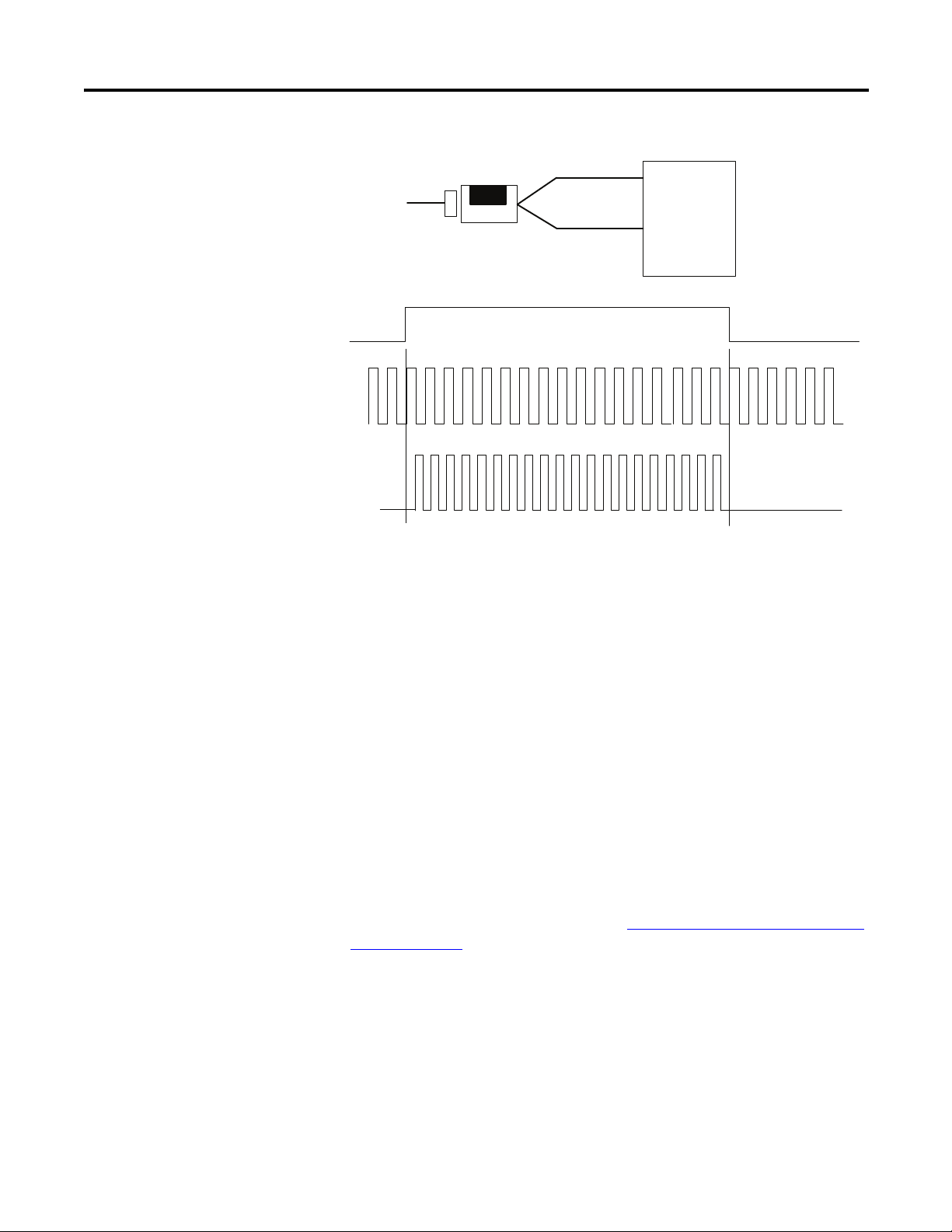
Rate Measurement Mode
Rockwell Automation Publication 1794-UM010D-EN-E - July 2013 11
Use the rate measurement mode to count incoming pulses for a user-specified
time interval. At the end of the interval, the module returns a value representing
the sampled number of pulses and a value indicating the incoming frequency.
When the count and frequency are updated, any associated outputs are checked
against their associated presets.
The value representing the total number of pulses is returned in input file words 4
(LSW) and 5 (MSW) for channel 0 and 6 (LSW) and 7 (MSW) for channel 1,
and the value indicating the incoming frequency is returned in words 0 (LSW)
and 1 (MSW) and 2 (LSW) and 3 (MSW). The total count equals the running
sum of the number of pulses received during the sample period. The operation of
rate measurement mode is shown in Figure Operation of the Rate Measurement
Mode on page 12.
Page 20
Overview of the Very High Speed Counter Module
If sample period is 50 ms, and count = 3, then frequency = 3/50 ms = 60 Hz
45895
EXAMPLE
A Input (pulse)
Internal sampling gate
Accumulated count
Operation of the Rate Measurement Mode
Encoder/Pulse generator
123
A Input
B (not used)
Z (not used)
(Gate/Reset)
Input A
Input B
Input Z
Time base
1794-VHSC
Frequency calculated,
outputs updated here
In , three counts have been accumulated during the user-selected time
period. If you had selected 50 ms as the sample period, the frequency
returned to the programmable controller processor would be:
Frequency = Counts/Sample period = 3 counts/50 ms = 60 Hz
Sample Period
You can set the sample period used in the frequency calculation in the rate
measurement mode. Allowable values are 10 ms to 3 s in 10 ms increments. The
default value is 1 s.
Connection to Counter Inputs
The only user connections used in the rate measurement mode are to phase A of
the module. The Z (gate/reset) and channel B terminals are not used in
this mode.
Pulse Width Modulation
The module can generate a pulse width modulation signal that may be tied to any
output. By specifying a period (configuration word 2) and gate interval
(configuration word 2 or 3) together with the PWM configuration word 2 or 3, a
counter and its first ON/OFF window comparator is assigned and the signal
generated. The actual duty cycle is specified by output words 2 and 3.
12 Rockwell Automation Publication 1794-UM010D-EN-E - July 2013
Page 21

Overview of the Very High Speed Counter Module
Output turns on at
count value of 2000
Output remains energized for
3000 additional counts
Output turns off at
count value of 5000
Outputs
The 1794-VHSC module has 4 outputs, isolated in groups of 2. Each of the
outputs is capable of sourcing current and will operate between 5 and 24V DC.
You must connect an external power supply to each of the outputs. The outputs
can source 1 A DC alone or in combination. The outputs are hardware-driven
and will turn on in about 25 s when the appropriate count value has been reached.
Enabling and Forcing Outputs
Outputs may be forced on or off independent of count or frequency value. To
force the outputs, they must first be enabled. Enabling the outputs is done
through a data table word 1, bits 1, 5, 9 and 13 (see Figure 1794-VHSC — High
Speed Counter Module Image Table Mapping on page 35). Once the outputs
have been enabled, they may be forced on by setting bits 0, 4, 8 or 12 in word 1.
The outputs can be forced off by setting the enable bit to 0.
Assigning Outputs to Counter Windows
By setting bits in the configuration block, you can assign the outputs on the
module to any of the various counter windows. You can assign any output to any
count window with no restrictions.
Operation of Outputs
When the outputs for the 1794-VHSC module are enabled and assigned to a
counter window they operate in an ON-OFF fashion. For example, assume that
the module were programmed to turn ON an output when a count value of 2000
was reached. Further, assume that the user desired to have the output remain
energized for a period of 3000 counts and then turn OFF. The end result would
be that the outputs would turn ON at count of 2000, would remain energized for
3000 additional counts, and would turn OFF at 5000 counts. The ON and OFF
values are circular around zero (see Figure On-Off Operation of Output
page 13).
On-Off Operation of Output
Using output 0 as an example, when the value in Counter ON Value is less than
the value in Counter OFF Value, the output turns on at 2000 and off at 5000. If
the value in Counter ON Value is greater than the value in Counter OFF Value,
the output turns off at 2000 and on at 5000 (see Figure Effect of Values in On/
Off Operation on page 14).
on
Rockwell Automation Publication 1794-UM010D-EN-E - July 2013 13
Page 22

Overview of the Very High Speed Counter Module
Output turns on at
count value of 2000
Output remains energized for
3000 additional counts
Output turns off at
count value of 5000
Output turns off at
count value of 2000
Output turns on at
count value of 5000
When values in Counter On Value are less than
values in Counter Off Value.
When values in Counter On Value are greater
than values in Counter Off Value.
Effect of Values in On/Off Operation
Isolation of Outputs
The module provides 850V DC isolation between each of the outputs and
the FlexBus.
Connecting Outputs to Counters
You can connect any of the outputs to any of the counter inputs. In this way, it is
possible to use the outputs to reset a counter or to cascade counters. If using the
outputs this way, make certain that the output voltage is compatible with the
chosen input.
What the Module Does
The very high speed counter module performs high-speed scaling calculation
operations for various industrial applications. The module interfaces with a
FLEX I/O family EtherNet/IP adapter which then communicates with a
programmable controller processor.
The adapter/power supply transfers data to and from the module over the
FlexBus. Instructions in the programmable controller facilitate this
communication and let you write output values and configure the module’s mode
of operation. Figure FLEX I/O Communication Process on page 15 describes the
communication process.
14 Rockwell Automation Publication 1794-UM010D-EN-E - July 2013
Page 23

FLEX I/O Communication Process
The adapter transfers your configuration
data to the module.
The adapter transfers the
data over the FlexBus.
The adapter and module determine
that the transfer was made without
error and input values are within a
specified range.
EtherNet/IP transfers the data to the
programmable controller data table.
The module converts
frequency signals into
binary format and stores
these values until the
adapter requests their
transfer.
External devices transmit
frequency signals to the module.
FlexBus
45896
Overview of the Very High Speed Counter Module
1
Allen-Bradley
4
VERY HIGH SPEED COUNTER MODULE
1794-VHSC
1
ok
5
2
3
6
1. The adapter transfers your configuration data and commands to the
module.
2. External devices generate input signals that are transmitted to the module.
3. The module converts these signals into binary format, and stores these
values and controls their output until the adapter requests their transfer.
4. The adapter transfers the data over the FlexBus.
5. The adapter and module determine that the transfer was made without
error and inputs values are within a specified range.
6. EtherNet/IP transfers the data to the programmable controller data table.
Chapter Summary
Rockwell Automation Publication 1794-UM010D-EN-E - July 2013 15
In this chapter you learned how your module operates, and how your module
communicates with the programmable controller.
Page 24

Overview of the Very High Speed Counter Module
Notes:
16 Rockwell Automation Publication 1794-UM010D-EN-E - July 2013
Page 25

Install Your FLEX I/O VHSC Module
Chapter
2
Overview
Before You Install Your Module
This chapter describes how to physically install the 1794-VHSC adapter on the
DIN rail and connect it to the EtherNet/IP network.
Topic Page
Before You Install Your Module
Power Requirements 17
Install the Module 18
Mount on a DIN Rail 18
Mount on a Panel or Wall 20
Mount the 1794-VHSC Module on the Terminal Base
Unit
Wiring Information 23
Connect Wiring to the FLEX I/O VHSC Input Module 24
Connect Wiring Using a 1794-TB3G, 1794-TB3GK or
1794-TB3GS Terminal Base Unit
Before installing your 1794-VHSC very high speed counter module, you need to:
• Calculate the power requirements of all modules in the FLEX I/O system,
and,
• Position the keyswitch on the terminal base.
17
21
24
Power Requirements
The wiring of the terminal base unit is determined by the current draw through
the terminal base. Make certain that the current draw does not exceed 10 A.
ATTENTION: Total current draw through the terminal base unit is
limited to 10 A. Separate power connections may be necessary.
Methods of wiring the terminal base units are shown in Wiring Inform
page 23.
Rockwell Automation Publication 1794-UM010D-EN-E - July 2013 17
ation on
Page 26

Install Your FLEX I/O VHSC Module
1
2
3
4
6
7
7
8
9
0
2
+
2
+
45319
Install the Module
Installation of the module consists of:
• mount the terminal base unit
• install the 1794-VHSC module into the terminal base unit
• install the connecting wiring into the terminal base unit
If you are installing your module into a terminal base unit that is already installed,
proceed to See Mount on a DIN Rail
on page 18.
Mount on a DIN Rail
ATTENTION: Do not remove or replace a terminal base unit when
power is applied. Interruption of the FlexBus can result in unintended
operation or machine motion.
Install the Terminal Base Unit
1. Remove the cover plug in the male connector of the unit to which you are
connecting this terminal base unit.
2. Check to make sure that the 16 pins in the male connector on the adjacent
device are straight and in line so that the mating female connector on this
terminal base unit will mate correctly.
Make certain that the female FlexBus connector is fully retracted into the
base unit.
18 Rockwell Automation Publication 1794-UM010D-EN-E - July 2013
Page 27

Install Your FLEX I/O VHSC Module
2
+
2
+
45320
2
+2+
45321
2
+
2
+
45322
3. Position the terminal base at a slight angle and hooked over the top of the
35 x 7.5 mm DIN rail A (Allen Bradley part number 199-DR1; 46277-3).
4. Slide the terminal base over tight against the adapter, or proceeding
terminal base. Make sure the hook on the terminal base slides under the
edge of the adapter, or proceeding terminal base, and the FlexBus
connector is fully retracted.
5. Pivot the terminal base onto the DIN rail with the top of the rail hooked
under the lip on the rear of the terminal base.
Use caution to make sure that the female FlexBus connector does not strike
any of the pins in the mating male connector.
6. Press down on the terminal base unit to lock the terminal base on the DIN
rail. If the terminal base does not lock into place, use a screwdriver or
similar device to open the locking tab, press down on the terminal base
until flush with the DIN rail and release the locking tab to lock the base in
place.
Gently push the FlexBus connector into the side of the adapter, or
proceeding terminal base to complete the backplane connection.
Rockwell Automation Publication 1794-UM010D-EN-E - July 2013 19
Page 28

Install Your FLEX I/O VHSC Module
(1.4)
35.5
0
1
7
2
3
4
6
7
8
9
2
+
2
+
1
2
3
4
45323
Millimeters
(inches)
For specific wiring information, refer to the installation instructions for the
module you are installing in this terminal base unit.
7. Repeat the above steps to install the next terminal base unit.
Ensure that the cover of the FlexBus connector on the last terminal base
unit is in place.
Mount on a Panel or Wall
Installation of a FLEX I/O system on a wall or panel consists of:
• laying out the drilling points on the wall or panel.
• drilling the pilot holes for the mounting screws.
• mounting the adapter mounting plate.
• installing the terminal base units and securing them to the wall or panel.
Use the mounting kit Cat. No. 1794-NM1 for panel or wall mounting.
1794-NM1 Mounting Kit
Description Description
1 Mounting plate for adapter 3 Terminal base unit (not included)
2 #6 Self-tapping screws 4 Adapter module (not included)
To install the mounting plate on a wall or panel:
Lay out the required points on the wall or panel as shown in the Figure Drilling
Dimensions for Panel or Wall Mounting on page 21.
20 Rockwell Automation Publication 1794-UM010D-EN-E - July 2013
Page 29

Drilling Dimensions for Panel or Wall Mounting
45327
IMPORTANT
Install Your FLEX I/O VHSC Module
Millimeters
(Inches)
21 (0.83)
35.5
(1.4)
58.5
(2.3)
35.5
(1.4)
58.5
(2.3)
35.5
(1.4)
8. Drill the necessary holes for the #6 self-tapping mounting screws.
9. Mount the mounting plate for the adapter module using two #6 self-
tapping screws – 18 screws are included for mounting up to 8 modules and
the adapter.
Make certain that the mounting plate is properly grounded to the
panel. Refer to Industrial Automation Wiring and Grounding
Guidelines, publication 1770-IN041
.
10. Hold the adapter at a slight angle and engage the top of the mounting plate
in the indention on the rear of the adapter module.
11. Press the adapter down flush with the panel until the locking lever locks.
12. Position the terminal base unit up against the adapter and push the female
bus connector into the adapter.
13. Secure to the wall with two #6 self-tapping screws.
14. Repeat for each remaining terminal base unit.
Mount the 1794-VHSC Module on the Terminal Base Unit
The 1794-VHSC module mounts on a 1794-TB3G or 1794-TB3GS terminal
base unit.
1. Rotate keyswitch (3) on terminal base unit (4) clockwise to position 1 as
required for the module.
Do not change the position of the keyswitch after wiring the terminal base
unit.
Rockwell Automation Publication 1794-UM010D-EN-E - July 2013 21
Page 30

Install Your FLEX I/O VHSC Module
1
2
3
4
5
6
7
8
Label here or under here
40231
FLEX I/O Terminal Base and Very High Speed Counter Parts
Description Description
1 FlexBus connector 5 Base unit
2 Latching mechanism 6 Alignment groove
3 Keyswitch 7 Alignment bar
4 Cap plug 8 Module
2. Make certain the FlexBus connector (1) is pushed all the way to the left to
connect with the neighboring terminal base or adapter.
You cannot install the module unless the connector is fully extended.
3. Make sure the pins on the bottom of the module are straight so they will
align properly with the connector in the terminal base unit.
ATTENTION: If you remove or insert the module while the
backplane power is on, an electrical arc can occur. This could
cause an explosion in hazardous location installations. Be sure that
power is removed or the area is nonhazardous before proceeding.
4. Position the module (8) with its alignment bar (7) aligned with the groove
(6) on the terminal base.
5. Press firmly and evenly to seat the module in the terminal base unit.
The module is seated when the latching mechanism is locked into the
module.
6. Remove cap plug and attach another terminal base unit to the right of this
terminal base unit if required.
Make sure the last terminal base has the cap plug in place.
22 Rockwell Automation Publication 1794-UM010D-EN-E - July 2013
Page 31

Install Your FLEX I/O VHSC Module
IMPORTANT
Digital input
module
Digital input
module
Digital output
module
VHSC
module
VHSC
module
Frequency input
module
VHSC
module
VHSC
module
Daisy-chaining
Individual
24V DC
24V DC
24V DC
24V DC
Wiring when total current draw is less than 10 A
Wiring when total current draw is greater than 10 A
Note: Do not use any digital modules in this configurations.
Note: Use this configuration if using any digital output
modules that could couple transients to the 24V supply.
1794-VHSC module wiring separate from digital wiring.
45897
The adapter is capable of addressing eight modules. Do not exceed a
maximum of eight terminal base units in your system.
Wiring Information
This section provides essential wiring information for the 1794-TB3G, 1794TB3GK, and 1794-TB3GS terminal base units. It also includes instructions for
connecting wiring to the FLEX I/O module.
Wire the Terminal Base Units (1794-TB3G shown)
ATTENTION: Take note of the following considerations when wiring
your terminal base units:
· AIl modules must be frequency or analog modules for the daisychain
configuration.
· Use the individual type of configuration for any "noisy" DC digital I/O
Rockwell Automation Publication 1794-UM010D-EN-E - July 2013 23
Wiring the FLEX I/O VHSC Input module is done using the 1794-TB3G,
1794-TB3GK or the 1794-TB3GS terminal base unit.
modules in your system.
· All modules powered by the same power supply must be frequency or
analog modules for the combination type of configuration.
Page 32

Install Your FLEX I/O VHSC Module
0123456789101112131415
16 17 18 19 20 21 22 23 24 25 26 27 28 29 30 31 32 33
34 35 36 37 38 39 40 41 42 43 44 45 46 47 48 49 50 51
A
B
C
A
B
C
1794-TB3G or 1794-TB3GK
1794-TB3GS
0...15
34...51
16...33
0 1 2 3 4 5 6 7 8 9 10 11 12 13 14 15
18 19 20 21 22 23 3324 25 26 27 28 29 30 31 3217
35 36 37 38 47 48 49 5034 51
16
39 40 41 42 43 44 45 46
Label placed at top of wiring area
34 and 50 = 24V DC
35 and 51 = common
16 and 33 = chassis
40…45 = chassis ground
35 and 51 = common
34 and 50 = 24V DC
16 and 33 = chassis ground
40…45 = chassis ground
45328
1794-TB3G, 1794-TB3GK and 1794-TB3GS Wiring Connections
Connect Wiring to the FLEX I/O VHSC Input Module
24 Rockwell Automation Publication 1794-UM010D-EN-E - July 2013
Wiring to the 1794-VHSC Input module is made through the terminal base unit
on which the module mounts.
The module is compatible with the 1794-TB3G, 1794-TB3GK and 1794TB3GS terminal base units.
Connect Wiring Using a 1794-TB3G, 1794-TB3GK or 1794-TB3GS Terminal Base Unit
1. Connect the individual signal wiring to numbered terminals on the 0…15
row (A) for 24V inputs (terminals 0…5 and 8…13) and 17…32 row (B) for
5V inputs (terminals 17…22 and 25…30) on the terminal base unit.
Connect the input devices as shown in Ta b l e
1794-VHSC High Speed Counter Module on page 26.
ATTENTION: Do not connect 24V signals to the 5V input terminals.
Permanent damage to the module will result.
2. Connect individual output wiring to terminals 6, 7 and 14, 15 on the
0…15 row (A) and terminals 23, 24 and 31, 32 on the 16…32 row (B) on
the terminal base unit. Connect output return wiring for channels 0, 1, 2,
and 3 to terminals 23, 24 31 and 32 respectively. Connect the output
devices as shown in Ta b l e
Speed Counter Module on page 26
3. Terminate shields to terminals 16 or 33 on row B, or 40…45 on row C.
Wiring connections for the 1794-VHSC High
Wiring connections for the
Page 33

Install Your FLEX I/O VHSC Module
4. Connect 24V DC to terminal 34 on the 34…51 row (C), and 24V
common to terminal 35 on the 34…51 row (C).
ATTENTION: To reduce susceptibility to noise, power frequency
modules and digital modules from separate power supplies. Do not
exceed a length of 10 m (33 ft) for DC power cabling.
5. If daisychaining the 24V DC power to the next 1794-TB3G, 1794-
TB3GK or 1794-TB3GS base unit, connect a jumper from terminal 50
(24V) on this base unit to terminal 34 and from terminal 51 (24V DC
common) to terminal 35 on the next 1794-TB3G, 1794-TB3GK or
1794-TB3GS base unit.
6. Connect output power wiring to terminals 37 (+) and 39 (-) for outputs
0 and 1, and terminals 46 (+) and 48 (-) for outputs 2 and 3.
ATTENTION: Use extreme care when connecting wiring to an
adjacent terminal base unit. Wiring for the 1794-TB3G and
1794-TB3GS terminal base units is different from other 1794 terminal
base units.
ATTENTION: Do not daisychain power or ground from the 1794TB3G, 1794-TB3GK or 1794-TB3GS terminal base unit to any AC or DC
digital module terminal base unit.
ATTENTION: 24V DC power must be applied to your module before
operation. If power is not applied, the module position will appear to
the adapter as an empty slot in your chassis. If the adapter does not
recognize your module after installation is completed, cycle power to
the adapter.
Rockwell Automation Publication 1794-UM010D-EN-E - July 2013 25
Page 34

Install Your FLEX I/O VHSC Module
17 18 19 20 21 22 23 24 25 26 27 28 29 30 31 32
0 1 2 3 4 5 6 7 8 9 10 11 12 13 14 15
16
35 36 37 38 39 40 41 42 43 44 45 46 47 48 49 50 51
34
COM
6 Chassis ground
for shields
Chassis GND
Chassis GND
AAB
BZ
O1O0 O3O2
O1O0
O3
O2
Z
A
AB
BZ
ZAAB
BZ
Z
AAB
BZ
Z
24V inputs
24V inputs
5V inputs
5V inputs
-V+V-V+V
+24V
COM
+24V
24V DC
base power
24V DC
base power
A, A - incremental encoder input A (+5 or +24V DC)
B B
- incremental encoder input B (+5 or +24V DC)
Z, Z - incremental encoder input Z (+5 or +24V DC)
O = sourcing outputs
R = returns for sourcing outputs
+V = +5 or +24V DC isolated power externally supplied for outputs (1 A max)
-V = negative isolated power connection (1 A max)
+24V DC = 24V DC terminal base power for module
COM = return for +24V DC terminal base power for module
Chassis Gnd = chassis ground for input or output cable shields
45898
Where:
Connections for Terminal Base 1794-TB3G or 1794-TB3GK shown
Wiring connections for the 1794-VHSC High Speed Counter Module
Incremental
Encoder Input
Input A 0 8
26 Rockwell Automation Publication 1794-UM010D-EN-E - July 2013
Input A
Input B 2 10
Input B
Input Z 4 12
Input Z
Input A 17 25
Input A
Input B 19 27
Terminal Base Units 1794-TB3G, 1794-TB3GK,
1794-TB3GS
Channel 0 Channel 1
+24V Inputs
19
311
513
+5V Inputs
Channel 0 Channel 1
18 26
Page 35

Install Your FLEX I/O VHSC Module
Wiring connections for the 1794-VHSC High Speed Counter Module
Input B
Input Z 21 29
Input Z 22 30
Output Sourcing Out Return Output Sourcing Out Return
O0 6 23 O1 7 24
O2 14 31 O3 15 32
+24V DC
Base power
+24V DC COM Terminals 35 and 51
+5V or +24V
Output power
-V Output power Terminals 39 and 48
Chassis GND Terminals 16, 33, and 40…45
20 28
Outputs
Terminals 34 and 50
Terminals 37 and 46
ATTENTION: Total current draw through the terminal base unit is
limited to 10 A. Separate power connections to the terminal base unit
may be necessary.
Rockwell Automation Publication 1794-UM010D-EN-E - July 2013 27
Page 36

Install Your FLEX I/O VHSC Module
45899
Example of Quadrature Encoder Differential Wiring to a 1794-TB3G or 1794-TB3GK
Terminal Base Unit
A
B
Z(Store count)
(Gate/reset)
1 2 3 4 5 6 7 8 9 10 11 12 13 14 15
0
0 1 2 3 4 5 6 7 8 9 10 11 12 13 14 15
16 17 18 19 20 21 22 23 24 25 26 27 28 29 30 31 32 33
34 35 36 37 38 39 40 41 42 43 44 45 46 47 48 49 50 51
1794-TB3G
Quadrature encoder
(for example: 845H-SJ__24DRY__ )
Mechanical switch
0…15
16…33
34…51
A
B
C
24V Base power
Chapter Summary
12V
+-
Solenoid
ATT ENTI ON: Keep exposed area of inner conductor as short
as possible.
This chapter provided you with instructions on how to install the module in an
existing programmable controller system and how to wire to a terminal
base unit.
28 Rockwell Automation Publication 1794-UM010D-EN-E - July 2013
Page 37

Communicate With Your Module
45900
Chapter
3
Overview
Communication Over the I/O Backplane
Read this chapter to familiarize yourself with configurable features on the
1794-VHSC Very High Speed Counter module
For Information About See Page
Communication Over the I/O Backplane
I/O Structure 31
Safe State Data 32
Device Actions 32
1794-VHSC — High Speed Counter Module Image
Table Mapping
Input Status Word Bits 32
Bit/Word Definitions 37
Configuration Word Definition 42
29
35
One 1794-AENT or 1794-AENTR EtherNet/IP adapter can interface up to
eight terminal base units with installed FLEX I/O modules, forming a FLEX I/O
system of up to eight slots. The adapter communicates to other network system
components (typically one or more controllers or scanners, and/or programming
terminals) over the EtherNet/IP network. The adapter communicates with its
I/O modules over the backplane.
0
EtherNet/IP
Adapter
Read
Write
Inputs
Status
Outputs
Configuration
Read
Words
Write
Words
15
Inputs
Status
Outputs
Configuration
Inputs
Status
Outputs
Configuration
Data is exchanged scheduled when mapped, or unscheduled using EtherNet/
IP instructions.
Rockwell Automation Publication 1794-UM010D-EN-E - July 2013 29
Page 38

Communicate With Your Module
Scheduled Data-Transfer
Scheduled data transfer:
•is continuous
• is asynchronous to the ladder-logic program scan
• occurs at the actual rate displayed in the Actual Packet Interval field on the
programming software I/O mapping (monitor) screen
Unscheduled Data-Transfer
Unscheduled operations include:
• unscheduled non-discrete I/O data transfers — through I/O transfer
instructions
• peer-to-peer messaging — through Message (MSG) instructions
• messaging from programming devices
Unscheduled messaging on an EtherNet/IP network is non-deterministic. Your
application and your configuration — number of nodes, application program,
NUT, amount of scheduled bandwidth used, and so on — determine how much
time there is for unscheduled messaging.
Module I/O Mapping
The I/O map for the 1794-VHSC module is divided into read words and write
words. Read words consist of input and status words, and write words consist of
output and configuration words. The number of read words or write words can
be 0 or more. The length of each I/O modules read words and write words vary in
size depending on module complexity. Each I/O module will support at least 1
input word or 1 output word. Status and configuration are optional, depending
on the module. The 1794-VHSC module has 9 input words, no status words, 4
output words and 56 configuration words.
Application of New Configurations
When a configuration is sent to the 1794-VHSC module, it is checked for
consistency before being applied. If an error is found in the configuration, the PE
bit (input word 8, bit 15) is asserted and the module locally retains its previous
configuration. To isolate any problems an improperly configured module may
have, the user application program (ladder program, for instance) should monitor
this error.
30 Rockwell Automation Publication 1794-UM010D-EN-E - July 2013
Page 39

Communicate With Your Module
45901
I/O Module Fault Bits
Not used
Node Address Changed Bit
Bit: 15 01413121110987654321
Slot 0
Slot 1
Slot 2
Slot 3
Slot 4
Slot 5
Slot 6
Slot 7
Node Address Changed Bit
Created by controller
{
45902
If the configuration is considered acceptable, the counter application specific
integrated circuit (ASIC) is disabled — counting is suspended and outputs are
shut off — while the ASIC is loaded with the new operational parameters.
I/O Structure
Output data is received by the adapter in the order of the installed I/O modules.
The Output data for Slot 0 is received first, followed by the Output data for Slot
1, and so on up to slot 7.
The first word of input data sent by the adapter is the Adapter Status Word. This
is followed by the input data from each slot, in the order of the installed I/O
modules. The Input data from Slot 0 is first after the status word, followed by
Input data from Slot 2, and so on up to slot 7.
EtherNet/IP adapter
Adapter Status
Slot 0 Input Data
Slot 1 Input Data
Slot 7 Input Data
Adapter Status
Slot 0 Output Data
Slot 1 Output Data
Read
Write
Slot 0 Slot 1 Slot 7
Rockwell Automation Publication 1794-UM010D-EN-E - July 2013 31
Adapter Input Status Word
The input status word consists of:
• I/O module fault bits — 1 status bit for each slot
• node address changed — 1 bit
•I/O status — 1 bit
Slot 7 Output Data
Page 40

Communicate With Your Module
The adapter input status word bit descriptions are show in Table Input Status
Wor d Bi ts on page 32.
Input Status Word Bits
Bit Description Bit Explanation
I/O Module Fault 0 This bit is set (1) when an error is detected in slot position 0.
1 This bit is set (1) when an error is detected in slot position 1.
2 This bit is set (1) when an error is detected in slot position 2.
3 This bit is set (1) when an error is detected in slot position 3.
4 This bit is set (1) when an error is detected in slot position 4.
5 This bit is set (1) when an error is detected in slot position 5.
6 This bit is set (1) when an error is detected in slot position 6.
7 This bit is set (1) when an error is detected in slot position 7.
Node address
changed
I/O state 9 Bit = 0 – idle
8 This bit is set (1) when the node address switch setting is changed
since power up.
Bit = 1 – run
10…15 Not used – set to 0.
Safe State Data
Device Actions
Possible causes for an I/O module fault are:
• transmission errors on the FLEX I/O backplane
•a failed module
• a module removed from its terminal base
• an incorrect module inserted in a slot position
• an empty slot
• a non-discrete module in the slot
The EtherNet/IP adapter does not provide storage for alternate module output
data during communication faults or processor idle state. This safe state data is
stored in the 1794-VHSC module and may be defined using configuration
software. Safe state data assures that a known output will be applied to the output
devices to maintain a previously designated safe operating condition during the
previously mentioned failure modes. This data is sent in the configuration block.
For more information, Table 1794-VHSC — High Speed Counter Module
Image Table Mapping on page 35.
Device actions include:
• communication fault behavior
• idle state behavior
• input data behavior upon module removal
32 Rockwell Automation Publication 1794-UM010D-EN-E - July 2013
Page 41

Communicate With Your Module
Communication Fault Behavior
You can configure the 1794-VHSC response to a communication fault. Upon
detection of a communication fault, the module can:
• leave the module output data in its last state (hold last state)
• reset the module output data to zero (reset)
• apply safe state data to the module output
Idle State Behavior
The 1794-VHSC module responds to idle state according to the
Communication Fault Behavior described above. The module can:
• leave the module output data in its last state (hold last state)
• reset the module output data to zero (reset)
• apply safe state data to the module output
Input Data Behavior upon Module Removal
I/O module input data sent by the adapter upon module removal is configurable.
The adapter can:
• reset the module output data to zero (reset)
• leave the module output data in the last state before module removal (hold
last state)
Frequency/Resolution Enhancement
This mode is only for use in modules with firmware revision D or later.
Frequency/Resolution Enhancement is a precise configuration which handles the
decimal position adjustment to frequency count. Using this mode allows the
module to read the frequency up to two positions to the right or left of the
decimal place. For example, a rounded frequency of 13 Hz can be displayed as
1257 or 12.57. The mode is only valid when the module is configured for Period
Rate or Continuous Rate.
Frequency Resolution/Enhancement reports the frequency back as a floating
point value in a single word and allows configuration of decimal places of
resolution.
The upper byte of the counter control word (output word 0) is reserved for
special mode, Enhancing Frequency/Resolution. In this mode, you can change
significant digits of frequency display based on output word 2 for channel 0 and
output word 3 for channel 1. Decimal point placement is absolute positioning. -2
Rockwell Automation Publication 1794-UM010D-EN-E - July 2013 33
Page 42

Communicate With Your Module
moves decimal point left 2 places dividing the frequency value by 100; +1 moves
the decimal point 1 place, multiplying by 10, and so on. This allows frequency
values to fit in a single word.
Applying the Frequency/Resolution Enhancement
To use this mode, proceed as follows.
ATTENTION: Use this enhancement mode with caution since no
checks are performed to verify data. Unintended operation can occur.
1. Power up the FLEX chassis, or put the controller into RUN mode, or
both. Let the 1794-VHSC module initialize as normal. Wait for the OK
indicator on the module to go solid green.
2. You must place ladder logic in your PLC that performs the following:
a. Set a value between -4 and +2 into output word 2 and/or 3.
b. Then set (1) the M11 bit in the upper byte of control word 0.
When the upper byte of the output word is not zero, the status
indicator flashes red, and the TF bit (bit 12, input word 8) is asserted.
c. Next, reset (0) the M11 bit in the upper byte of output control word 0.
Clearing the upper byte of output word 0 restores the module to an
operational state, clears the TF bit in input word 8 and returns the
indicator to green. The module is now in enhanced mode.
3. To tu rn th is f ea t ur e o f f :
a. Set output word 2 or 3 to zero (no value)
b. Set (1) the M11 bit
c. Then reset (0) the M11 bit
34 Rockwell Automation Publication 1794-UM010D-EN-E - July 2013
Page 43

Communicate With Your Module
45903
1794-VHSC — High Speed Counter Module Image Table Mapping
I/O Image
Input Size
1…9Words
Output Size
0…4Words
Configuration Size
56 Words
0
1
2
3
4
5
6
7
PE FP NR TF OS OS OS OS C1 C0 ZF ZS C1 C0 ZF ZS
8
0
1
Reserved
0 LC OE FO 0 LC OE FO 0 LC OE FO 0 LC OE FO
2
3
0
1
2
3
4
Channel 0 Current Count (least significant word)
Channel 0 Current Count (most significant word)
Channel 1 Current Count (least significant word)
Channel 1 Current Count (most significant word)
Channel 0 Stored/Accumulated Count (least significant word)
Channel 0 Stored/Accumulated Count (most significant word)
Channel 1 Stored/Accumulated Count (least significant word)
Channel 1 Stored/Accumulated Count (most significant word)
M11
Reserved
VRCPCR0 VRCP CR
0
Channel 0 PWM Output Value (0…95.00%)
Channel 1 PWM Output Value (0…95.00%)
Counter Configuration
Filter Selection
Time Base Value/PWM Period
Channel 0 Gate Interval
Channel 1 Gate Interval
5
6
7
8
9
10
11
12
13
Channel 0 Rollover Value (least significant word)
Channel 0 Rollover Value (most significant word)
Channel 1 Rollover Value (least significant word)
Channel 1 Rollover Value (most significant word)
Channel 0 Preset Value (least significant word)
Channel 0 Preset Value (most significant word)
Channel 1 Preset Value (least significant word)
Channel 1 Preset Value (most significant word)
14
15
16
00000000 S3S4S2 S1F4F3F2F1
Reserved
Channel 0 Scaler
Channel 1 Scaler
Rockwell Automation Publication 1794-UM010D-EN-E - July 2013 35
Page 44

Communicate With Your Module
45904
Configuration Size
(continued)
56 Words
17
00000000 S3S4S2 S1F4F3F2F1
18
00000000 S3S4S2 S1F4F3F2F1
19
00000000 S3S4S2 S1F4F3F2F1
20
21
22
23
24
25
26
27
28
29
30
31
32
First Counter 1st On Value (least significant word)
First Counter 1st On Value (most significant word)
First Counter 1st Off Value (least significant word)
First Counter 1st Off Value (most significant word)
First Counter 2nd On Value (least significant word)
First Counter 2nd On Value (most significant word)
First Counter 2nd Off Value (least significant word)
First Counter 2nd Off Value (most significant word)
First Counter 3rd On Value (least significant word)
First Counter 3rd On Value (most significant word)
First Counter 3rd Off Value (least significant word)
First Counter 3rd Off Value (most significant word)
First Counter 4th On Value (least significant word)
33
34
35
36
37
38
39
40
41
42
43
44
46
47
48
First Counter 4th On Value (most significant word)
First Counter 4th Off Value (least significant word)
First Counter 4th Off Value (most significant word)
Second Counter 1st On Value (least significant word)
Second Counter 1st On Value (most significant word)
Second Counter 1st Off Value (least significant word)
Second Counter 1st Off Value (most significant word)
Second Counter 2nd On Value (least significant word)
Second Counter 2nd On Value (most significant word)
Second Counter 2nd Off Value (least significant word)
Second Counter 2nd Off Value (most significant word)
Second Counter 3rd On Value (least significant word)
45
Second Counter 3rd On Value (most significant word)
Second Counter 3rd Off Value (least significant word)
Second Counter 3rd Off Value (most significant word)
Second Counter 4th On Value (least significant word)
49
econd Counter 4th On Value (most significant word)
S
36 Rockwell Automation Publication 1794-UM010D-EN-E - July 2013
Page 45

Bit/Word Definitions
Input Word Bit Definition
Word 0 00…15
(00…17)
Word 1 00…15
(00…17)
Word 2 00…15
(00…17)
Word 3 00…15
(00…17)
Word 4 00…15
(00…17)
Word 5 00…15
(00…17)
Word 6 00…15
(00…17)
Word 7 00…15
(00…17)
Channel 0 current count – The current count consists of 2 words (32
bits) representing the current count of the 24-bit counter (in encoder, X2
encoder, X4 encoder, PWM) or the frequency (in periodrate,
continuousrate, rate measurement.). The range of values is
(0 < value < 16,777,215).
Channel 1 current count – The current count consists of 2 words (32
bits) representing the current count of the 24-bit counter (in encoder, X2
encoder, X4 encoder, PWM) or the frequency (in period/rate,
continuous/rate, rate measurement.). The range of values is
(0 < value < 16,777,215).
Channel 0 stored/accumulated count – These are 32-bit long word
values representing the stored count of the counter at the time of some
specified event.
These words are not updated in counter modes (counter, X1 encoder, X2
encoder, X4 encoder) without store modes selected. With store modes
selected, it is the counter value at the time of the specified Z input
event.
In PWM configuration, it is the counter value at the end of the period
specified by the product of the time base times gate interval.
In period/rate and continuous/rate, it is the total accumulation of
unscaled Z pulses (if scaling is set to 128, the accumulator will increase
by 128 counts). The maximum frequency that accumulation can follow is
(200Hz X Scaler value).
In rate measurement, it is the total number of pulses seen at the A input
accumulated over each period as specified by the product of time base
times gate interval. The range of values occupy the entire 32-bit size
from 0 < value < 4,294,967,295. These words are not cleared by
changing the configuration.
Channel 1 stored/accumulated count – These are 32-bit long word
values representing the stored count of the counter at the time of some
specified event.
These words are not updated in counter modes (counter, X1 encoder, X2
encoder, X4 encoder) without store modes selected.With store modes
selected, it is the counter value at the time of the specified Z input
event.
In PWM configuration, it is the counter value at the end of the period
specified by the product of the time base times gate interval.
In period/rate and continuous/rate, it is the total accumulation of
unscaled Z pulses (if scaling is set to 128, the accumulator will increase
by 128 counts). The maximum frequency that accumulation can follow is
(200Hz X Scaler value).
In rate measurement, it is the total number of pulses seen at the A input
accumulated over each period as specified by the product of time base
times gate interval. The range of values occupy the entire 32-bit size
from 0 < value < 4,294,967,295. These words are not cleared by
changing the configuration.
Communicate With Your Module
Rockwell Automation Publication 1794-UM010D-EN-E - July 2013 37
Page 46

Communicate With Your Module
Bit/Word Definitions
Input Word Bit Definition
Word 8 Module Channel Status Word
00 Zero input status bit (ZS) for Channel 0 – This bit represents
01 Zero frequency detected bit (ZF) for Channel 0 – Only used during
02, 03 Stored/data count bit (C0, C1) for Channel 0 – This count cycles thru
04 Zero input status bit (ZS) for Channel 1 – This bit represents
05 Zero frequency detected bit (ZF) for Channel 1 – Only used during
06, 07 Stored/data count bit (C0, C1) for Channel 1 – This count cycles
08…11
(10…13)
the present status of the Z input.
0 = Off
1 = Input on
This bit is uneffected by Z invert, ZI, in the counter configuration word.
frequency configurations (period/rate, continuous/rate, and rate
measurement). In period/rate and continuous/rate, counts are acquired
during on state of the Z input. At very low frequencies, the counter
saturates, indicating a zero frequency detect. The time it takes to
determine a zero frequency in these 2 configurations can be as long as
6.7 s (16,777,215 counts X 1/5 MHz X 2 half cycles of Z). In rate
measurement, pulses on Z are counted over a sample interval specified
by the product of time base X gate interval.
The time to detect a zero frequency is determined by the sample
interval
example: time base = 0.100s, gate interval = 3 is 300 ms to
determine ZF.
00, 01, 10, 11, 00... Each time the stored/accumulated count words are
updated, C(0,1) is incremented. The PLC sample rate, including network
delay and program scan, must be as fast or faster than the frequency of
the event which updates.
the present status of the Z input.
0 = Off
1 = Input on
frequency configurations (period/rate, continuous/rate, and rate
measurement). In period/rate and continuous/rate, counts are acquired
during on state of the Z input. At very low frequencies, the counter
saturates, indicating a zero frequency detect. The time it takes to
determine a zero frequency in these 2 configurations can be as long as
6.7 s (16,777,215 counts X 1/5 MHz X 2 half cycles of Z). In rate
measurement, pulses on Z are counted over a sample interval specified
by the product of time base X gate interval.
The time to detect a zero frequency is determined by the
sample interval
example: time base = 0.100 s, gate interval = 3 is 300 ms to
determine ZF.
through 00, 01, 10, 11, 00... Each time the stored/accumulated count
words are updated, C(0,1) is incremented. The PLC sample rate,
including network delay and program scan, must be as fast or faster
than the frequency of the event which updates.
Output status indicators (OS) – Bit 08 corresponds to output 0, bit 09
to output 1, bit 10 to output 2, and bit 11 to output 3.
0 = output Off
1 = output On
38 Rockwell Automation Publication 1794-UM010D-EN-E - July 2013
Page 47

Communicate With Your Module
Bit/Word Definitions
Input Word Bit Definition
Word 8 12 (14) Test/fail bit (TF) – If the flexbus power or terminal base power is
13 (15) Not ready status bit (NR) – Whenever 24V DC power is applied to the
14 (16) Field power fault bit (FP) – If the 24V DC module power drops, the FP
15 (17) Programming error bit (PE) – This bit is asserted if incomplete,
applied and the module fails during hardware tests, a fatal error occurs.
The TF bit is asserted and the red module indicator turns on. An error
code will be set in the module/channel status word which can be read
using an instruction. The TF bit is also asserted if the upper byte of the
counter control word is not zero.
The upper byte of the counter control word (output word 0) is reserved
for special mode, Enhancing Frequency/Resolution. To use this mode,
set bit 11, and set a value in output word 2 and/or word 3. When the
upper byte of word 0 is not zero, the red module status indicator will
flash and the TF bit is asserted to indicate the module has entered a
test-mode state. Clearing the upper byte of output word 0 restores the
module to an operation state, clears the TF bit and returns the indicator
to green.
Change significant digits of frequency display based on word 14 for
channel 0 and word 15 for channel 1 (-2 moves decimal point left 2
places dividing the frequency value by 100; +1 moves the decimal point
1 place, multiplying by 10, and so on).
This allows frequency values to fit in a single word.
Note: To use Frequency/Resolution Enhancement feature provides
appropriate configuration for each frequency mode (Mode 5,6,7).
Firmware revision D changed decimal point placement to absolute
positioning. Revision D firmware also checks for placement to be in the
range of -4…+2. A value outside the range moves the decimal point to
the zero position. Moving the decimal point to the left allows high
frequencies, (commonly present in rate measurement) to fit within a
single word. Moving the decimal point to the right allows low
frequencies (commonly present in period and continuous rate modes) to
have resolution displayed to 0.1 Hz and 0.01 Hz. Do not use scalars of Z/
128, Z/64, Z/32 and Z/16 when using this test mode.
module, the hardware must be initialized. The NR bit will be asserted
and the red module indicator will flash. If the red indicator continues
flashing, and the green indicator momentarily turns on, the 24V DC
power is below the module minimum.
bit is asserted, the green module indicator flashes, the module outputs
turn off, and the module enters an idle state reporting status as it waits
for power to be restored.
Note: this bit does not indicate status of either output customer
power supply.
incorrect or conflicting set of configuration parameters are sent to the
module. The green module status indicator will flash and an error code
will be placed in bits 11:0 of the module/channel status word. The
module will not enter a normal operating state. Bit definitions are
shown in Table Input Status Word Bits
on page 32.
Rockwell Automation Publication 1794-UM010D-EN-E - July 2013 39
Page 48

Communicate With Your Module
Bit/Word Definitions
Output
Word
Word 0 00…15
Word 1 00…15
Bit Definition
(00…17)
00 Channel 0 Counter reset bit (CR) – A 0 to 1 transition of this bit
01 Channel 0 Counter preset bit (CP) – A 0 to 1 transition of this bit sets
02 Channel 0 Value reset bit (VR) – A 0 to 1 transition of this bit clears
03 This bit is always 0.
04 Channel 1 Counter reset bit (CR) – A 0 to 1 transition of this bit
05 Channel 1 Counter preset bit (CP) – A 0 to 1 transition of this bit sets
06 Channel 1 Value reset bit (VR) – A 0 to 1 transition of this bit clears
07 This bit is always 0.
08…10
(10…12)
11 (13) Frequency/Resolution enhancement bit (M11) Set this bit to 1 for
12…15
(14…17)
(00…17)
00 Output 0 Force output bit (FO) – When set to 1, output is turned on if
01 Output 0 Output enable bit (OE) – When set to 1, output can be
Counter Control Word
clears the counter. Outputs are adjusted according to the window
compare values.
the counter to the value specified by the preset words. Outputs are
adjusted according to the window compare values.
the stored/accumulated count words.
clears the counter. Outputs are adjusted according to the window
compare values.
the counter to the value specified by the preset words. Outputs are
adjusted according to the window compare values.
the stored/accumulated count words.
Reserved for factory use.
frequency precision configuration (Refer to Word 8 Bit/Word Definitions
on page 39 for details on frequency precision configuration).
Note: You must place a value between -4 and +2 in output word 2 and/
or 3 to shift the decimal position accordingly.
Reserved for factory use.
Output Control Word
OE is 1. When FO = 0, output can be controlled by a compare match or
as directed by the PWM settings.
turned on from a force on, compare match or as directed by the PWM
settings. When OE = 0, the associated output is turned off.
40 Rockwell Automation Publication 1794-UM010D-EN-E - July 2013
Page 49

Bit/Word Definitions
Communicate With Your Module
02 Output 0 Local control bit (LC) – When set to 1, output is controlled
03 Not used – set to 0.
04 Output 1 Force output bit (FO) – When set to 1, output is turned on if
05 Output 1 Output enable bit (OE) – When set to 1, output can be
06 Output 1 Local control bit (LC) – When set to 1, output is controlled
07 Not used – set to 0.
08 (10) Output 2 Force output bit (FO) – When set to 1, output is turned on if
09 (11) Output 2 Output enable bit (OE) – When set to 1, output can be
10 (12) Output 2 Local control bit (LC) – When set to 1, output is controlled
11 (13) Not used – set to 0.
12 (14) Output 3 Force output bit (FO) – When set to 1, output is turned on if
13 (15) Output 3 Output enable bit (OE) – When set to 1, output can be
14 (16) Output 3 Local control bit (LC) – When set to 1, output is controlled
15 (17) Not used – set to 0.
the counter if the FlexBus power is lost (for instance, the module
detects a FlexBus reset signal).
Note: When FlexBus power is lost, communication to the PC is lost.
When LC = 0, the module clears its OE bit at a loss of FlexBus power.
Set this bit as appropriate in the safe state word, since a
communication fault occurs after adapter power is lost.
OE is 1. When FO = 0, output can be controlled by a compare match or
as directed by the PWM settings.
turned on from a force on, compare match or as directed by the PWM
settings. When OE = 0, the associated output is turned off.
the counter if the FlexBus power is lost (for instance, the module
detects a flexbus reset signal).
Note: When flexbus power is lost, communication to the PC is lost.
When LC = 0, the module clears its OE bit at a loss of FlexBus power.
Set this bit as appropriate in the safe state word, since a
communication fault occurs after adapter power is lost.
OE is 1. When FO = 0, output can be controlled by a compare match or
as directed by the PWM settings.
turned on from a force on, compare match or as directed by the PWM
settings. When OE = 0, the associated output is turned off.
the counter if the FlexBus power is lost (for instance, the module
detects a FlexBus reset signal).
Note: When FlexBus power is lost, communication to the PC is lost.
When LC = 0, the module clears its OE bit at a loss of flexbus power. Set
this bit as appropriate in the safe state word, since a communication
fault occurs after adapter power is lost.
OE is 1. When FO = 0, output can be controlled by a compare match or
as directed by the PWM settings.
turned on from a force on, compare match or as directed by the PWM
settings. When OE = 0, the associated output is turned off.
the counter if the FlexBus power is lost (for instance, the module
detects a FlexBus reset signal).
Note: When FlexBus power is lost, communication to the PC is lost.
When LC = 0, the module clears its OE bit at a loss of FlexBus power.
Set this bit as appropriate in the safe state word, since a
communication fault occurs after adapter power is lost.
Rockwell Automation Publication 1794-UM010D-EN-E - July 2013 41
Page 50

Communicate With Your Module
Bit/Word Definitions
Configuration Word Definition
Configuration
Word
Configuration
Word 0
Bit Definition
Bits 00…03 03 02 01 00 Counter 0
Bits 08…11
(10…13)
Bits 04…07 06 05 04 Counter 0
Bits 12…14
(14…16)
Bit 15 (17) Invert the Z signal – 0 = Z not inverted; 1 = Z inverted
Word 2 00…15
Word 3 00…15
Counter Configuration – The upper byte of this word configures counter 1, the lower byte configures counter 0.
11
(13)10(12)09(11)08(10)
0 0 0 0 Counter
000 1Encoder
001 0Encoder X2
001 1PWM
010 0Encoder X4
0 1 0 1 Period/Rate
0 1 1 0 Continuous/Rate
0 1 1 1 Rate Measurement
Mode Selection
14
(16)13(15)12(14)
0 0 0 Store count disabled
0 0 1 Mode 1 – store/continue
0 1 0 Mode 2 – store/wait/resume
0 1 1 Mode 3 – store;reset/wait/start
1 0 0 Mdoe 4 – store;reset/start
(00…17)
(00…17)
Counter 1
Counter 1
Channel 0 PWM Output value – When the module is configured for
PWM, the time base is enabled, the counter for the respective channel,
its gate interval, rollover and 1st on and 1st off value are used. Ties can
be used to direct the PWM signal to any or all outputs.
The range of the PWM values is 0 ≤ value ≤ 9500 decimal (for instance,
0.00% ≤ value ≤ 95.00%). The actual duty cycle at the output depends
on the turn on and turn off times of the MOSFET, energy storage
capability of the cable/load and the resistance from output to return.
Channel 1 PWM Output value – When the module is configured for
PWM, the time base is enabled, the counter for the respective channel,
its gate interval, rollover and 1st on and 1st off value are used. Ties can
be used to direct the PWM signal to any or all outputs.
The range of the PWM values is 0 ≤ value ≤ 9500 decimal (for instance,
0.00% ≤ value ≤ 95.00%). The actual duty cycle at the output depends
on the turn on and turn off times of the MOSFET, energy storage
capability of the cable/load and the resistance from output to return.
42 Rockwell Automation Publication 1794-UM010D-EN-E - July 2013
Page 51

Configuration Word Definition
Communicate With Your Module
Configuration
Word
Word 1 Filter Selection – Only 1 filter selection can be chosen at a time. Frequency = 50% duty cycle.
Word 2 Bits 00…15
Word 3 Bits 00…15
Word 4 Bits 00…15
Word 5 Bits 00…15
Word 6 and 7 Bits 00…15
Word 8 and 9 Bits 00…15
Word 10 and 11 Bits 00…15
Word 12 and 13 Bits 00…15
Bit Definition
Bits 00…03 03 02 01 00 Counter 0
Bits 08…11
(10…13)
Bit 12 (14) Input A filter bit (AF) – 0 = not filtered; 1 = apply filter to input
Bit 13 (15) Input B filter bit (BF) – 0 = not filtered; 1 = apply filter to input
Bit 14 (16) Input Z filter bit (ZF) – 0 = not filtered; 1 = apply filter to input
Bit 15 (17) Set to 0.
(00…17)
(00…17)
(00…17)
(00…17)
(00…17)
(00…17)
(00…17)
(00…17)
11
(13)10(12)09(11)08(10)
000 0No filter
0 0 0 1 50 kHz (10 μs + 0 μs/-1.6 μs)
0 0 1 0 5 kHz (100 μs + 0 μs/-13.2 μs)
0 1 0 0 500 Hz (1.0 ms + 0 ms/-1.25 μs)
1 0 0 0 50 Hz (10.0 ms + 0 ms/-1.25 ms)
Time base – Sets the fundamental time base for both counters. Resolution in ms, with a minimum of 10 ms intervals
(10 ms = 10; 1 s = 1000).
Time base must be entered when PWM and rate measurement are configured. The maximum programmed
value is 3000.
Channel 0 Gate interval – Sets the individual counter gate interval using the time base setting as its time unit.
Actual gate interval is time base X gate interval (for instance, time base of 10 X gate interval of 5 = 50 ms). Maximum
value is 3 s.
Gate interval must be entered when PWM and rate measurement are configured.
Channel 1 Gate interval – Sets the individual counter gate interval using the time base setting as its time unit.
Actual gate interval is time base X gate interval (for instance, time base of 10 X gate interval of 5 = 50 ms). Maximum
value is 3 s.
Gate interval must be entered when PWM and rate measurement are configured.
Do not use – reserved.
Channel 0 Rollover – Sets the number of counts the counter accumulates before rolling over. For example, a setting
of 1000 produces a count sequence of 998, 999, 0, 1, 2... while incrementing; and 2, 1, 0, 999, 998... while
decrementing. Rollover is a 32-bit number with a usable range of 16,777,216. In PWM, this value is zero; in count, X1
encoder, X2 encoder and X4 encoder configurations, it must be some specified nonzero number. The value doesn.t
matter in period/rate, continuous/rate and rate measurement configurations.
Channel 1 Rollover – Sets the number of counts the counter accumulates before rolling over. For example, a setting
of 1000 produces a count sequence of 998, 999, 0, 1, 2... while incrementing; and 2, 1, 0, 999, 998... while
decrementing. Rollover is a 32-bit number with a usable range of 16,777,216. In PWM, this value is zero; in count, X1
encoder, X2 encoder and X4 encoder configurations, it must be some specified nonzero number. The value doesn.t
matter in period/rate, continuous/rate and rate measurement configurations.
Channel 0 Preset – This word sets the preset value the counter is loaded with when CP is asserted. This number has
a range of 0 ≤ value ≤ 16,777,216.
Channel 1 Preset – This word sets the preset value the counter is loaded with when CP is asserted. This number has
a range of 0 ≤
value ≤ 16,777,216.
Counter 1
Rockwell Automation Publication 1794-UM010D-EN-E - July 2013 43
Page 52

Communicate With Your Module
Configuration Word Definition
Configuration
Word
Word 14 Bits 00…15
Word 15 Bits 00…15
Bit Definition
(00…17)
00 Z Fmins (frequency at which the 24-bit counter overflows) = 0.149 Hz
01 Z/2 Fmins (frequency at which the 24-bit counter overflows) = 0.298 Hz
02 Z/4 Fmins (frequency at which the 24-bit counter overflows) = 0.596 Hz
03 Z/8 Fmins (frequency at which the 24-bit counter overflows) = 1.192 Hz
04 Z/16 Fmins (frequency at which the 24-bit counter overflows) = 2.384 Hz
05 Z/32 Fmins (frequency at which the 24-bit counter overflows) = 4.768 Hz
06 Z/64 Fmins (frequency at which the 24-bit counter overflows) = 9.537 Hz
07 Z/128 Fmins (frequency at which the 24-bit counter overflows) = 19.073 Hz
Channel 0 Scaler – This word scales the Z signal in period/rate and continuous/rate modes. If the filter is
applied, the filtered Z signal is scaled. Set only 1 bit of the Scaler.
Selecting a Scaler causes accumulated counts to be adjusted accordingly (for instance, selecting a Scaler of 128
increases the accumulated count by 128 after 128 Z pulses have been received).
We recommend using the filter to reduce erroneous frequency readings any time you use the Scaler on the
Z input.
Channel 1 Scaler – This word scales the Z signal in period/rate and continuous/rate modes. If the filter is
applied, the filtered Z signal is scaled. Set only 1 bit of the Scaler.
Selecting a Scaler causes accumulated counts to be adjusted accordingly (for instance, selecting a Scaler of 128
increases the accumulated count by 128 after 128 Z pulses have been received).
We recommend using the filter to reduce erroneous frequency readings any time you use the Scaler on the
Z input.
44 Rockwell Automation Publication 1794-UM010D-EN-E - July 2013
Page 53

Configuration Word Definition
Communicate With Your Module
Configuration
Word
Words 16…19 Bits 00
Words 20…51 Bits 00…15
Words 52…55 Bits 00…15
Bit Definition
01
02
03
04
05
06
07
Bits 08…15
(10…17)
(00…17)
(00…17)
Output Ties – These bits connect the specified output to the appropriate compare window. There are 8 windows, 4 per
counter. Each output can be connected to any number of windows, from 1 to 8.
F1 = Tie output to first counter 1st window
F2 = Tie output to first counter 2nd window
F3 = Tie output to first counter 3rd window
F4 = Tie output to first counter 4th window
S1 = Tie output to second counter 1st window
S2 = Tie output to second counter 2nd window
S3 = Tie output to second counter 3rd window
S4 = Tie ouput to second counter 4th window
Set to 0.
Counter On and Off – These words program each of the 4 counter.s (first and second counter) on and off values. The
first compare window for each counter is used in PWM, and when programmed for PWM, the associated compare
window should remain at 0. The range of each entry is 0 ≤ value ≤ 16,777,215. When a tie is connected to a window
comparator, that window must be specified. These windows are always interpreted as counts, regardless of the
configuration setting, and can be computed as follows:
counts = (Scaler X 2.5E6)/desired frequency (for period/rate and continuous/rate)
counts = time base X desired frequency (for rate measurement)
Safe State Values – When the PLC transitions to PROG mode or a communication fault occurs, the module copies the
safe state words into its real time working buffer. The definitions are identical to the those in the counter control word,
except entering a PWM safe state value outside the range 0…9500 results in a Hold Last State.
Word 52 is Counter Control Safe State;
word 53 is Output Control Safe State;
word 54 is Channel 0 PWM Safe State
word 55 is Channel 1 PWM Safe State.
Chapter Summary
In this chapter you learned how to communicate with your module. Read the
next chapter to learn how to interpret the module LED status indicators.
Rockwell Automation Publication 1794-UM010D-EN-E - July 2013 45
Page 54

Communicate With Your Module
46 Rockwell Automation Publication 1794-UM010D-EN-E - July 2013
Page 55

Chapter
VERY
HIGH SPEED COUNTER MODULE
1794-VHSC
ZBAZBA
Allen-Bradley
1OUT
3210
OUT0
A
B
45906
C
Interpret Status Indicators for your
FLEX I/O Module
4
Overview
Status Indicators
Use this chapter to troubleshoot the very high speed counter module by
interpreting the indicators.
The module contains indicators for each of the following:
1794-VHSC Module
A = Status Indicators –
A — Status of input A
B — Status of input B
Z — Status of gate input Z
The indicators are multiplexed in 2 groups (A0, B0, Z0, O0/O1; and A1, B1, Z1,
O2/O3) at a frequency of 488Hz. If inputs or outputs change at or near that
frequency, the associated indicator will vary in brightness.
B = Insertable label for writing individual I/O assignments.
Rockwell Automation Publication 1794-UM010D-EN-E - July 2013 47
C = Power/status indicator - indicates power applied to module and status
of module.
Page 56

Interpret Status Indicators for your FLEX I/O Module
Use the following table to determine the indicator conditions and status.
Status Indicator Identification
Indicator State Status
A (status of input A) Yellow Input A active.
Off Input A not active.
B (status of input B) Yellow Input B active.
Off Input B not active.
Z (status of input Z) Yellow Input Z active.
Off Input Z not active.
Out O, 1, 2, 3 Yellow Output is on.
Off Individual output is off.
When an active indicator (yellow) is lighted, a valid signal (active high or active
low) is present at the input terminals.
The module power/status indicator (OK) shows power applied to the module,
and the status of the module.
Power/Status Indicator Interpretation
Indicator State Status
OK Solid red • Hardware diagnostic error, TF set to 1 and
module/channel status contains error code.
• Hardware runtime failure (that is, watchdog timeout),
module communication ceases.
Flashing red • Module is configuring hardware, NR is set to 1.
• Module is in test mode (bits 8…15 of counter control
word are nonzero), TF set to 1.
Flashing red
(with occasional
flashing green)
Solid green Module is active and acting normally.
Flashing green • Module is not configured.
Module 24V power is below minimum rating.
• Programming error, PE is set to 1 and error code is
supplied in bits 0…11 of module/channel status word.
• Field power fault, FP set to 1.
• Adapter powered down, and module local power
still active.
• ControlNet cable disconnected.
• PLC in PROG mode.
48 Rockwell Automation Publication 1794-UM010D-EN-E - July 2013
Page 57

Interpret Status Indicators for your FLEX I/O Module
Diagnostic Codes Returned by the Module
If an incomplete, incorrect or conflicting set of configuration parameters are sent
to the module, the PE bit is asserted, the green module status indicator flashes,
and an error code is displayed in bits 0…11 of the module/channel status word.
These codes are identified below.
Diagnostics Reported by Input Data Word 8
Read Word Bit Indication
Word 8 00 A reserved configuration or mode was programmed.
01 ZF/BF/AF were selected and no filter was programmed, or multiple
filters were selected.
02 A timebase was entered that was not a multiple of 10, or the timebase is
out of range (>3000, that is 3 s).
03 A configuration requiring a timebase was selected and no gate interval
was set, or the gate interval is out of range (>3 s) or the product of
timebase and gate interval is greater than 3 s.
04 A rollover of zero was programmed through PWM was not selected; a
rollover was programmed and PWM was selected; or the rollover is out
of range (1 ≤ rollover ≤ 16,777,216).
Word 05 The preset (1 ≤ preset ≤ 16,777,216) is out of range.
06 A configuration was selected that requires a scalar, and no scalar was
programmed or multiple scalars were selected.
07 A tie has been connected to an unprogrammed window.
08 Counter 0 window ON and OFF values are equal and not zero or counter
0 window ON and OFF value greater than 16,777,215.
09 Counter 1 window ON and OFF values are equal and not zero or counter
1 window ON and OFF value greater than 16,777,215.
10 Reserved
11
Chapter Summary
During hardware self-tests, when either FlexBus power or terminal base power is
first applied and a fatal error occurs, the TF bit is asserted and the red module
status indicator turns on. An error code is placed in the lower byte of the
module/channel status word to indicate the failed resource.
Error Code Definitions
Read Word Bit 02 01
Word 8 00…07 0
0
0
1
00 Dec. Definition
011RAM test failed.
102ROM checksum test failed.
1 1 3 EEPROM test failed.
004Programmable Gate Array
loading failed
All other combinations not used.
This chapter described how to troubleshoot your adapter module by interpreting
the status indicators and module/channel status word error codes.
Rockwell Automation Publication 1794-UM010D-EN-E - July 2013 49
Page 58

Interpret Status Indicators for your FLEX I/O Module
Notes:
50 Rockwell Automation Publication 1794-UM010D-EN-E - July 2013
Page 59

Specifications
Appendix
A
Overview
This appendix contains general and environmental specifications and
certifications for the FLEX I/O Very High Speed Counter Module
Input Specifications
Attribute Value
Number of input
channels
Number of inputs per
counter
Input voltage 5V DC or 15…24V DC (Determined by terminal base terminations)
Input current 5V DC terminations:
Voltage, input, off-state 5V DC terminations: <
Current, input, off-state <
Voltage, input, on-state 5V DC terminations: >2.6V DC
Current, input, on-state >5mA
Voltage, on-state, max 5V DC terminations: ±6V
Input frequency, max 1.0 MHz counter and encoder X1 (no filters)
Input filter selections Off, 10μs, 100μs, 1.0ms, 10.0ms per A/B/Z group
2
2 groups of A/A, B/B, and Z/Z pairs with 5V DC or
15…24V DC terminations
19.1 mA @ 5V DC
25.7 mA @ 6V DC
15…24V DC terminations:
6.1 mA @ 15V DC
10.2 mA @ 24V DC
1.25V DC
15…24V DC terminations: <1.8V DC
0.25 mA
15…24V DC terminations: >12.5V DC
15…24V DC terminations (Refer to Derating Curve)
500 kHz encoder X2 (no filters)
250 kHz endocer X4 (no filters)
.
Output Specifications
Attribute Value
Number of outputs 2 isolated groups of 2:
Output control Outputs can be tied to 8 compare windows
Voltage range, output
supply
Leakage current,
off-state
Voltage drop, on-state 5V DC terminations: 0.9V DC @ 0.5 A
Rockwell Automation Publication 1794-UM010D-EN-E - July 2013 49
(0.5A @ 5V DC, max; 1.0A @ 12…24V DC, max)
5…7V DC; 10…31V DC
Less than 300 μA
12…24V DC terminations: 0.9V DC @ 1.0 A
Page 60

Specifications
Output Specifications
Attribute Value
Current, on-state, max 5V DC terminations: 0.5 A
12…24V DC terminations: 1.0 A
Current per
output pair, max
5V DC terminations: 0.5 A
12…24V DC terminations: 1.0 A
Short circuit current 5V DC terminations: 0.9A
12…24V DC terminations: 4.0A
Outputs are short-circuit protected and turned off until power is cycled.
Surge current 2A for 50 ms, repeatable every 2 s
Delay Time
Off to On
On to Off
25 μs (load dependent)
150 μs (load dependent)
General Specifications
Attribute Value
Module location 1794-TB3G and 1794-TB3GS
External DC power supply
voltage range, nom
Supply voltage 19.2…31.2V DC (includes 5% AC ripple)
Supply current 100 mA @ 24V DC
Dimensions, HxWxD
(with module installed on
terminal base)
Isolation voltage 50V (continuous), Basic Insulation Type, between six isolated areas
FlexBus current 75 mA @ 5V DC (with terminal base power off)
Power dissipation, max 5.0 W @ 31.2V DC
Thermal dissipation, max 17.1 BTU/hr @ 31.2V DC
Indicators
(field side driven, logic
side indication)
Keyswitch position 1
24V DC
94 x 94 x 69 mm
(3.7 x 3.7 x 2.7 in.)
including:
FlexBus
Module 24V DC power
A0/B0/Z0 inputs
A1/B1/Z1 inputs
00/01 and output power supply 1
02/03 and output power supply 2
Tested @ 850V DC for 1 s
1 green/red power/status indicator
6 yellow input status indicators – logic side
4 yellow output tatus indicators – logic side
50 Rockwell Automation Publication 1794-UM010D-EN-E - July 2013
Page 61

Specifications
Environmental Specifications
Attribute Value
Temperature, operating IEC 60068-2-1 (Test Ad, Operating Cold),
Temperature,
nonoperating
Relative humidity IEC 60068-2-30 (Test Db, Unpackaged Damp Heat):
Vibration IEC60068-2-6 (Test Fc, Operating): 5g @ 10…500 Hz
Shock, operating IEC60068-2-27 (Test Ea, Unpackaged shock): 30 g
Shock, nonoperating EC60068-2-27 (Test Ea, Unpackaged shock): 50 g
Emissions CISPR 11: Group 1, Class A (with appropriate enclosure)
ESD Immunity IEC 61000-4-2:
Radiated RF immunity IEC 61000-4-3:
EFT/B immunity IEC 61000-4-4:
Surge transient immunity IEC 61000-4-5:
Conducted RF immunity IEC 61000-4-6:
Enclosure type rating None (open-style)
Wire size Determined by installed terminal base
Wiring category
(1)
Terminal base screw
torque
(1)
Use this Conductor Category information for planning conductor routing. Refer to Industrial Automation Wiring
and Grounding Guidelines, publication 1770-4.1
IEC 60068-2-2 (Test Bd, Operating Dry Heat),
IEC 60068-2-14 (Test Nb, Operating Thermal Shock):
0…55 °C (32…131 °F)
IEC 60068-2-1 (Test Ab, Un-packaged Non-operating Cold),
IEC 60068-2-2 (Test Bb, Un-packaged Non-operating Dry Heat),
IEC 60068-2-14 (Test Na, Un-packaged Non-operating Thermal Shock):
-40…85 °C (-40…185 °F)
5…95% non-condensing
6 kV contact discharges
8 kV air discharges
10V/m with 1 kHz sine-wave 80% AM from 80…2000 MHz
10V/m with 200 Hz 50% Pulse 100% AM at 900 MHz
10V/m with 200 Hz 50% Pulse 100% AM at 1890 MHz
10V/m with 1 kHz sine-wave 80% AM from 2000…2700 MHz
±2 kV @ 5 kHz on power ports
±2 kV @ 5 kHz on signal ports
±1 kV line-line(DM) and ±2 kV line-earth(CM) on power ports
±1 kV line-line(DM) and ±2 kV line-earth(CM) on signal ports
±2 kV line-earth(CM) on shielded ports
10V rms with 1 kHz sine-wave 80%AM from 150 kHz…80 MHz
2 – on signal ports
2 – on power ports
Determined by installed terminal base
.
Rockwell Automation Publication 1794-UM010D-EN-E - July 2013 51
Page 62

Specifications
0
10
0
20
30
10 20 30 40 50 55 60
25
24
29
The area within the curve represents the safe operating range for the module
under various conditions of user supplied 24V DC supply voltages and ambient
temperatures.
This includes all possible mounting positions, including inverted horizontal.
Ambient Temperature °C
Input
Voltage
(V)
45907
Certifications
Certification (when
product is marked)
Description
(1)
CE European Union 2004/108/EC EMC Directive, compliant with:
EN 61326-1; Meas./Control/Lab., Industrial Requirements
EN 61000-6-2; Industrial Immunity
EN 61000-6-4; Industrial Emissions
EN 61131-2; Programmable Controllers (Clause 8, Zone A & B)
C-Tick Australian Radiocommunications Act, compliant with:
AS/NZS CISPR 11; Industrial Emissions
KC Korean Registration of Broadcasting and Communications Equipment,
compliant with:
Article 58-2 of Radio Waves Act, Clause 3
(1)
See the Product Certification link at www.ab.com for Declarations of Conformity, Certificates, and other
certification details.
Derating Curve
52 Rockwell Automation Publication 1794-UM010D-EN-E - July 2013
Page 63

Appendix
B
Programming Your Very High Speed
Counter Module
To initiate communication between the 1794-VHSC very high speed counter
module and your PLC processor, you must use RSLogix 5000 software.
Refer to the RSLogix software manuals for information on communicating with
this 1794-VHSC very high speed counter module.
Rockwell Automation Publication 1794-UM010D-EN-E - July 2013 53
Page 64

Programming Your Very High Speed Counter Module
Notes:
54 Rockwell Automation Publication 1794-UM010D-EN-E - July 2013
Page 65

Index
Numerics
1794-TB3G 25, 27, 28, 29
1794-TB3GK 27, 28, 29
1794-TB3GS 25, 27, 28, 29
1794-VHSC 34, 49
description 5
features 5
interpret status indicator 49
A
adapter 21, 23, 24, 25, 29
1794-VHSC 21
capabilities 27
install 21
maximum capacity 27
additional resources 3
B
backplane 23, 26
behavior
communication fault
idle state 36
input data 36
36
C
cabling
29
length
power 29
chassis 28, 29
codes
diagnostic
error 51
compatible
terminal base
configuration
error
connect 28
connector 26
female 22
FlexBus 23
male 22
count
scale
store 10
counter mode
continuous
counters
reset
51
28
34
10
8
10
current draw 21
D
daisychain 29
data transfer
scheduled
unscheduled 34
definitions
bit/word
dimensions
drilling
DIN rail 21, 23
drilling
illustration
34
41
25
25
E
encoder mode
8
X1
X2 8
X4 8
F
female connector 22
FLEX I/O
27
VHSC
FlexBus 18, 22, 23, 24, 26
connector 23, 26
interruption 22
I
I/O data transfer
non-discrete
I/O map 34
I/O module
fault
36
fault bits 35
I/O status 35
indicator
state
status 50
indicators
interpret
input
data behavior
gate/reset 10
install
physically
installation 23
drilling 24
34
50
49
36
21
Rockwell Automation Publication 1794-UM010D-EN-E - July 2013 55
Page 66

Index
hazardous location 26
install connecting wiring 22
install module 21
mount terminal base 21
mounting kit 24
terminal base mounting 25
wall or panel mounting 24
K
keyswitch 25
position 25
L
location
hazardous
26
M
male connector 22
messaging
from programming devices
peer-to-peer 34
mode
continuous/rate
period/rate 14
rate measurement 15
module
installation
position 29
specifications 53
mounting kit 24
14
21
34
P
panel
mounting
power
backplane
cabling 29
module 29
supply 29
24
26
S
specification
DIN rail
specifications
certifications
derating curve 56
environmental 55
general 53
status indicator 49, 54
23
56
T
terminal base 22, 24, 26, 27, 28, 29, 36
grounding 29
replace 22
wiring 28
terminal base unit 28
U
unscheduled
messaging
operations 34
34
N
network
EtherNet/IP
21
O
operation
unintended
output
values
outputs
connecting to counters
enabling 17
force 17
isolation 18
56 Rockwell Automation Publication 1794-UM010D-EN-E - July 2013
22
18
18
value
VHSC module
wiring 24, 28, 29
V
10
rollover
scaler 12, 14
wiring
28
W
1794-TB3G, 1794-TB3GS, 1794-TB3GK 27
connect 29
connecting 22
frequency module 28
Page 67

Page 68

Rockwell Otomasyon Ticaret A.Ş., Kar Plaza İş Merkezi E Blok Kat:6 34752 İçerenköy, İstanbul, Tel: +90 (216) 5698400
Rockwell Automation Support
Rockwell Automation provides technical information on the Web to assist you in using its products.
http://www.rockwellautomation.com/support/, you can find technical manuals, a knowledge base of FAQs, technical and
At
application notes, sample code and links to software service packs, and a MySupport feature that you can customize to make
the best use of these tools.
For an additional level of technical phone support for installation, configuration, and troubleshooting, we offer
TechConnect support programs. For more information, contact your local distributor or Rockwell Automation
representative, or visit
Installation Assistance
If you experience a problem within the first 24 hours of installation, review the information that is contained in this
manual.
You can contact Customer Support for initial help in getting your product up and running.
United States or Canada 1.440.646.3434
Outside United States or
Canada
http://www.rockwellautomation.com/support/.
Use the Worldwide Locator at http://www.rockwellautomation.com/support/americas/phone_en.html, or contact
your local Rockwell Automation representative.
New Product Satisfaction Return
Rockwell Automation tests all of its products to ensure that they are fully operational when shipped from the
manufacturing facility. However, if your product is not functioning and needs to be returned, follow these procedures.
United States Contact your distributor. You must provide a Customer Support case number (call the phone number above to obtain
Outside United States Please contact your local Rockwell Automation representative for the return procedure.
one) to your distributor to complete the return process.
Documentation Feedback
Your comments will help us serve your documentation needs better. If you have any suggestions on how to improve this
document, complete this form, publication
RA-DU002, available at http://www.rockwellautomation.com/literature/.
Rockwell Automation Publication 1794-UM010D-EN-E - July 2013
Copyright © 2013 Rockwell Automation, Inc. All rights reserved.
 Loading...