

Page 1

Bulletin 1494V Variable Depth Disconnect Switch Installation Instructions
(Cat 1494V-DS30; -DSX30 - Series D; 1494V-DS60; -DSX60 - Series D)
(Cat 1494V-DS100; -DSX100 - Series D; 1494V-DS200; -DSX200 - Series D)
WARNING
WARNING
To prevent electrical shock, disconnect from power source before installing or servicing. Follow
NFPA 70E requirements. Install in suitable enclosure. Keep free from contaminants.
The following procedures are critical to the proper operation of the disconnect handle and switch.
Failure to follow these steps can result in damage to the equipment and/or serious injury or death to the
operator.
Table of Contents Page
Quick Installation Guide 2
Disconnect Switch Installation
-
- Disconnect Handle Installation
- Cutting Connecting Rod
Quick Installation Guide (continued) 3
Connecting Rod Installation
-
Connecting Rod Adjustment Procedure 4
Enclosure Without Handle Cutout 5
- Locate Handle
- Drill Handle Holes
Door Catch Mounting Bracket Installation 6
Disconnect Switch Installation 7
-
Locate Disconnect Switch
- Install Disconnect Switch
- Assemble and Install Line Terminal Guard
Trailer Fuse Block Installation (30A, 60A, 100A) 8
Trailer Fuse Block Installation (200A) 9
Fuse Clip Installation and Phase Barrier Replacement (30A, 60A) 10
Fuse Clip Installation and Phase Barrier Replacement (100A) 11
Fuse Clip Installation (200A)
12
Fuse Clip Installation (Switch Rating 200A) for 400A Class J Fuses 13
Phase Barrier Replacement (200A) 14
Bulletin 1494V Disconnect Switch Kit 15
Bulletin 1494V Disconnect Switch Kit Optional Accessory List 16
PN-47400
DIR 10000056505 (Version 00)
Printed in U.S.A.
Page 2
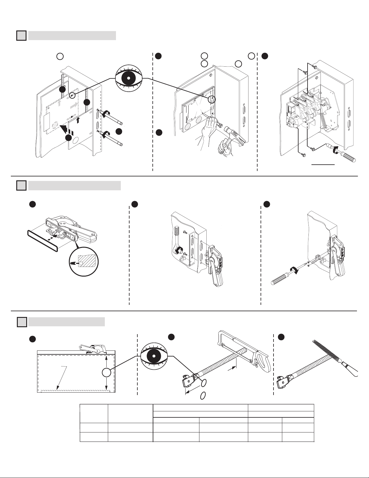
QUICK INSTALLATION GUIDE
Disconnect Switch Installation (Right hand installation shown. For left hand installation follow similar procedure.)
1
Use template A to locate handle holes on mounting plate.
4
OLE
TOP HANDLE H
HE
MEASURE TO
INSIDE OF T
HOLD FLUSH
TO INSIDE
TOP OF ENCLOSURE
OF ENCLOSURE
TAPE
BOTTOM HANDLE H
A
Disconnect Handle Installation
2
Install gasket.
1
2
TOP
OLE
HOLD FLUSH
TO INSIDE
OSURE
MEASURE TO
INSIDE OF THE
OF ENCLOSURE
TOP OF ENCL
BOTT
3
A
11
Overlay template B (30 A - 100 A) over A .
5
7
Overlay template C (200 A) over A .
3 - 1/16"
TOP
2 - 1/4"
2 - 1/4"
switch
HE
HOLD FLUSH
4 - 11/16"
TO INSIDE
MEASURE TO
NCLOSURE
INSIDE OF T
OF ENCLOSURE
Switch Mounting Holes
TOP OF E
Center punch and drill (4) 11/64" holes for
tap-tite screws provided with
5 - 1/4"
BOTT
C
A
or
B
1
6
Center punch and
drill (4) holes
for thread forming
(TAP-TITE) screws
provided with switch.
11/64" Dia. (30A - 100A)
7/32" Dia (200A)
Install handle and spring bracket.
2 3
Install disconnect switch.
23 - 37 lb-in
(30A - 100A)
40 - 60 lb-in
(200A)
Install defeater lever.
Cutting Connecting Rod
3
Measure working depth of enclosure.
1
Mounting
Plate
Working Depth
(Inside Flange
of Enclosure to
Mounting Plate)
Enclosure
Connecting
Rod
Standard
Extended
N
Catalog
Number
1494V-RA3
1494V-RA4
30-40 lb-in
Measure, mark and
2
cut connecting rod.
N minus 3-1/8"
(30A - 100A)
N minus 3-1/4"
(200A)
30A - 60A - 100A Disconnect Switches
“N”
Min.
6 - 3/4"
6 - 3/4"
21 - 5/8"
Max.
9 - 1/8"
7-11 lb-in
Remove burrs
3
200A Disconnect Switches
“N”
Min.
8 - 1/2"
8 - 1/2"
Max.
10 - 1/4"
22 - 3/4"
PN-47400
DIR 10000056505 (Version 00)
(2)
Page 3
QUICK INSTALLATION GUIDE (CONTINUED)
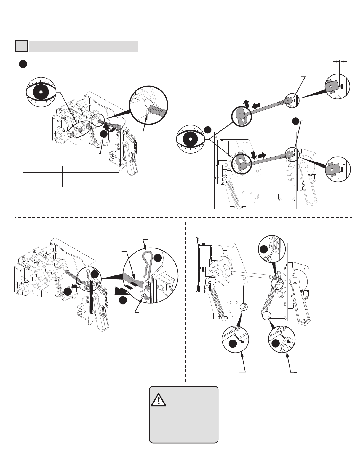
Connecting Rod Installation
4
Verify that disconnect switch and handle are in "OFF"
1
position. (Switch blades will be visible)
Drive Bar
Rotate connecting rod into
drive bar (see table).
Switch Rating
30A - 60A - 100A
200A
Full Turns Engagement
2
10
13
Push rod down and verify if rod
is approximately 1/8" from
touching bottom of bolt head.
(If not, rotate rod up to 5 full
turns in either direction)
(200A)
Push down
4
3
(30A - 60A - 100A)
Pull up
1/8" Gap
Push rod down and
verify if rod is nearly
touching bottom of bolt
head. (If not, rotate rod
up to 5 full turns in
either direction)
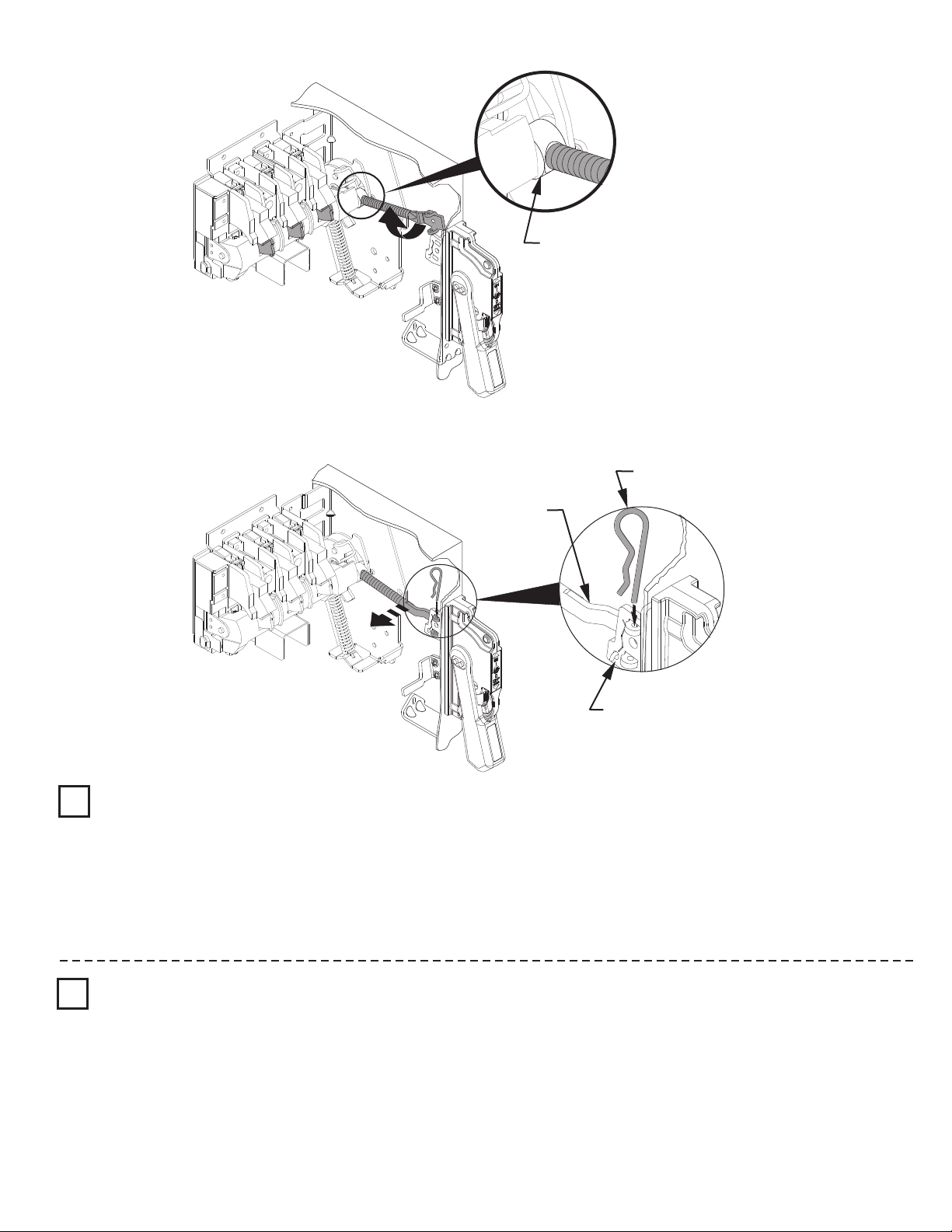
Hitch Pin
Connecting
Rod
6
7
6
5
5
Primary Link
8a
Enclosure depth
8 in. or less
8b
Enclosure depth
greater than 8 in.
ATTENTION
PN-47400
DIR 10000056505 (Version 00)
CHECK FOR PROPER
OPERATION
(3)
Page 4
Connecting Rod Adjustment Procedure
Drive Bar
Hitch Pin
"ON" Position
1
Move disconnect handle to the "ON" position.
If switch does not fully close, return handle to "OFF" position.
Remove link spring hitch pin and disengage the connectiong rod from the primary link.
Turn connecting rod counter-clockwise (1 or more) full turns.
Re-engage connecting rod in primary link of handle, insert hitch pin and re-test
Repeat - as necessary.
Re-install link spring
Connecting
Rod
Primary Link
"OFF" Position
2
Move disconnect handle to the "OFF" position.
If switch does not fully open, return handle to "ON" position.
Remove hitch pin and link spring, then disengage the connectiong rod from the primary link.
Turn connecting rod clockwise (1 or more) full turns.
Re-engage connecting rod in primary link of handle, insert hitch pin and re-test.
Repeat - as necessary.
Re-install link spring
PN-47400
DIR 10000056505 (Version 00)
(4)
Page 5
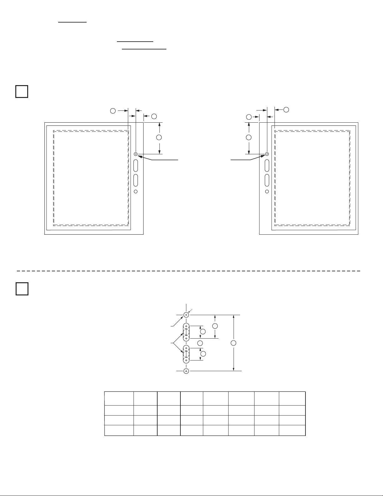
Enclosure without Handle Cutout
L Enclosures with a Flange Thickness less than 3/16" use dimensions below to install disconnect handle.
L Enclosures with a Flange Thickness 3/16" and greater use dimensions in alternate Mounting Kit 1494V-H3 to install disconnect
handle.
L Multi-Door Enclosures may require the need for a more rigid flange / mounting plate system, such as a Channel Support Kit. Use
dimensions in Channel Support Kit 1494V-H15, if handle is mounted on top of the channel.
Locate Handle
1
Drill Handle Holes
2
C
Right Hand Flange
C
B
A
B
A
Top Handle Hole
Left Hand Flange
Top Handle Hole
To make slot drill (3) 1/2" diameter holes and remove burrs
NEMA
SIZE
30A, 60A
100A
200A
PN-47400
DIR 10000056505 (Version 00)
A
(min)
4 - 5/8"
6 - 1/16"
10 - 1/8"
(2) .265 Dia. Holes
H
J
H
Enclosure Dimensions
B
(min)
1 - 1/8"
1 - 1/8"
1 - 1/8"
C
(max)
1 - 1/16"
1 - 1/16"
1 - 1/16"
(5)
4 - 11/16"
4 - 11/16"
4 - 11/16"
G
F
F
G
1 - 9/16"
1 - 9/16"
1 - 9/16"
H
1"
1"
1"
J
7/8"
7/8"
7/8"
Page 6

Door Catch Bracket Installation
Right hand installation shown (for left hand installation follow similar procedures)
Door Catch Mounting Bracket:
L Provided with projections for welding.
L Projections can also be used as a guide for drilling holes.
L Can be used as a template to drill corresponding holes in the enclosure door.
L User to supply the hardware for fastening the bracket.
L The bracket hardware must be inaccessible to unauthorized personnel.
L Fasteners must provide the degree of ingress protection for the environmental rating of the enclosure.
Dimension K (3/4" to 1")
L When using small disconnect handle kit only (1494F-P1, -M1 or -S1), use door catch provided with handle kit.
L When using small disconnect handle kit and small door hardware kits (1494V-L1, -LL1, -L2 or -LL2), use door catch
provided with door hardware kit.
Dimension K (1-1/8" to 1-3/8")
L When using small disconnect handle kit only (1494F-P1, -M1 or -S1), use door catch (40492-080-02) which can be
ordered from factory.
L When using small disconnect handle kit and large door hardware kits (1494V-L3 or -LL3), use door catch provided with
door hardware kit.
Door Catch
Mounting Bracket
Top
Enclosure Door
Door Catch
Mounting Bracket
Door Catch
NEMA
SIZE
30A, 60A
100A
200A
C
E
TOP VIEW
A
(min)
4 - 5/8"
6 - 1/16"
10 - 1/8"
B
(min)
1 - 1/8"
1 - 1/8"
1 - 1/8"
B
C
D
Enclosure Dimensions
C
(max)
1 - 1/16"
1 - 1/16"
1 - 1/16"
A
D
1 - 5/8"
1 - 5/8"
1 - 5/8"
2 - 3/8"
2 - 3/8"
2 - 3/8"
B
E
Flange
Thickness
Enclosure
Base
F
4 - 11/16"
4 - 11/16"
4 - 11/16"
G
1 - 9/16"
1 - 9/16"
1 - 9/16"
B
A
Door Catch
K
H
1"
1"
1"
J
7/8"
7/8"
7/8"
C
E
Door Catch
Mounting
Bracket
PN-47400
DIR 10000056505 (Version 00)
Right Hand Flange Left Hand Flange
Top Handle Hole
Door Catch
Mounting
D
D
(6)
Bracket
Page 7

Disconnect Switch Installation
Locate Disconnect Switch
1
FF
CC
HH HH
GG
AAAAAAAA
AA
BB BB
Top Handle Hole
AAAAAAAAAAAAAAAAAAAAAAEE
CC
FF
GG
Right Hand Flange Left Hand Flange
Panel Mounting Dimensions
Switch
Size
AA BB CC DD
EE
(4 Mounting Plate Holes)
FF
HH
DDDD
30A, 60A, 100A
200A
3-1/16" 2-1/2" 2-1/4" 5-1/4"
3-9/16" 3-9/16" 2" 8-1/4" 3-9/16" 4-1/4" 1-1/8"7/32" Dia.
3-1/16"
11/64" Dia.
2-1/4"GG----
This dimension can be 2-1/4" if necessary, to avoid interference with panel mounting studs in some 8 inch deep enclosures.
Install Disconnect Switch Assemble and Install Line Terminal Guard
2 3
23 - 37 lb-in (30A - 100A)
40 - 60 lb-in (200A)
LINE TERMINAL GUARD
LINE TERMINAL GUARD
PN-47400
DIR 10000056505 (Version 00)
(7)
Page 8

Trailer Fuse Block Installation (Switch Rating 30A - 100A)
Trailer Fuse Block Location
1
Note: Not required for non-fusible disconnect switch applications.
30 Amp Trailer Fuse Block (1494V-FS30)
Amps Voltage Class Fuse
30
30
30
30
60
60
60
60
250
600
600
600
250
600
600
600
H/R
H/R
J
HRCII-C
H/R
H/R
J
HRCII-C
A
2-27/32"
5-5/8"
2-27/32"
4-3/16"
3-5/8"
6-1/8"
3"
4-3/16"
Torque (lb-in)Fuse
Block
23
Fuse
Clip
-
37 22-37 20-25 20-25
Lug to
Terminal
Wire
into Lug
A
(2) 11/64" Dia. Holes
2-1/4"
60 Amp Trailer Fuse Block (1494V-FS60)
Amps Voltage Class Fuse
30
30
30
30
60
60
60
60
100
100
Amps Voltage Class Fuse
60
60
60
60
100
100
100
100
200
250
600
600
600
250
600
600
600
600
600
250
600
600
600
250
600
600
600
600
H/R
H/R
J
HRCII-C
H/R
H/R
J
HRCII-C
J
H/R
100 Amp Trailer Fuse Block (1494V-FS100)
H/R
J
H/R
HRCII-C
H/R
H/R
J
HRCII-C
J
A
2-27/32"
5-5/8"
2-27/32"
4-3/16"
3-5/8"
6-1/8"
3"
4-3/16"
4-15/16"
8-1/8"
A
4-3/16"
3-9/16"
6-11/16"
4-11/16"
6-11/16"
8-11/16"
5-1/2"
7-9/16"
6-1/4"
Block
-
23
23
-
Block
-
23
23
-
Torque (lb-in)Fuse
Fuse
37
23-37 40-60 45-50
37 16-22 40-60 45-50
37
37 16-22 90-110 150-165
Lug to
Clip
Terminal
Torque (lb-in)Fuse
Fuse
22
Lug to
Clip
Terminal
-
37 90-110 150-165
into Lug
Wire
Wire
into Lug
Install Trailer Fuse Block
2
PN-47400
DIR 10000056505 (Version 00)
23 - 37 lb-in
(8)
Page 9

railer Fuse Block Installation (Switch Rating 200A)
Trailer Fuse Block Location
1
Note: Not required for non-fusible disconnect switch applications.
Amps Voltage Class Fuse
100
100
100
100
200
200
200
200
B
400
250
600
600
600
250
600
600
600
600
200 Amp Trailer Fuse Block (1494V-FS200)
60
Torque (lb-in)Fuse
Fuse
Clip
-
16
-
16
22
22
Lug to
Terminal
175
H/R
H/R
J
HRCII-C
H/R
H/R
J
HRCII-C
J
B
5-7/8"
7-7/8"
4-5/8"
4-5/8"
6-3/4"
9-1/4"
5-3/8"
5-3/8"
6-1/4"
Block
40
-
Wire
into Lug
-
200 275-305
1 - 1/8"
Install Trailer Fuse Block
2
2"
(2) 7/32" Dia. Holes
40 - 60 lb-in
PN-47400
DIR 10000056505 (Version 00)
(9)
Page 10

Switch Rating (30A, 60A Rating)
Fuse Clip Installation
1
2
23 - 37 lb-in
2
1
Phase Barrier Replacement Kit
1494F-PH2
NOTE: Fuse clips and lugs must be removed to add or replace phase barriers.
1 2
1
40392-098
2
CLICK
1
CLICK
2
40392-097
PN-47400
DIR 10000056505 (Version 00)
(10)
Page 11

Fuse Clip Installation (Switch Rating 100 Amp)
1
Phase Barrier Replacement Kit
1494F-PH3
Switch Phase Barrier
16 - 22 lb-in
1
2
2
2
1
Trailer Block Phase Barrier
23 - 37 lb-in
1
2
Fuse Clip Size and Class
60 A
100 A
200 A
200 A
600V H - R
600V H - R
600V H - R
250V H - R
2
2
1
1
Fuse Clip Size and Class
60 A
60 A
100 A
100 A
250V H - R
600V J
250V H - R
600V J
600V J200 A
3
PN-47400
DIR 10000056505 (Version 00)
1
CLICK
1
2
2
(11)
CLICK
Page 12

Fuse Clip Installation (Switch Rating 200A)
Switch for Right Hand Mechanism
1
16 - 22 lb-in
2
Switch for Left Hand Mechanism
1
16 - 22 lb-in
2
1
1
Switch for Right Hand Mechanism
2
1
23 - 37 lb-in
2
Switch for Left Hand Mechanism
2
23 - 37 lb-in
1
2
PN-47400
DIR 10000056505 (Version 00)
(12)
Page 13

Fuse Clip Installation (Switch Rating 200A) for 400A Class J Fuses (Cat. No. 1401-N171)
NOTICE
Switch with Right Hand Mechanism
1 1
Use of 400A fuses will void the UL listing of this product.
16 - 22 lb-in
2
1
Switch with Left Hand Mechanism
16 - 22 lb-in
2
1
Switch with Right Hand Mechanism
2 2
150 - 200 lb-in
Switch with Left Hand Mechanism
PN-47400
DIR 10000056505 (Version 00)
150 - 200 lb-in
(13)
Page 14

Phase Barrier Replacement Kit (Switch Rating 200A)
1494F-PH4
1
1
2
4
40 - 60 lb-in
2
CLICK
3
1
2
3
CLICK
PN-47400
DIR 10000056505 (Version 00)
(14)
Page 15

Bulletin 1494V Disconnect Switch Kit
Disconnect Kit
Switch
Handle
Connecting
Rod
Cat No.
Switch with Right Hand Mechanism
1494V-DS30 (30A)
1494V-DS60 (60A)
1494V-DS100 (100A)
1494V-DS200 (200A)
Switch with Left Hand Mechanism
1494V-DSX30 (30A)
1494V-DSX60 (60A)
1494V-DSX100 (100A)
1494V-DSX200 (200A)
1494F-M1 (5-1/2" Painted Metal) (30A - 200A)
1494F-P1 (5-1/2" Molded) (30A - 200A)
1494F-S1 (5-1/2" Stainless Steel) (30A - 200A)
1494V-RA3 (Standard) (30A - 100A)
Enclosure Working Depth: 6-3/4" to 9-1/8"
1494V-RA3 (Standard) (200A)
Enclosure Working Depth: 8-1/2" to 10-1/4"
1494V-RA4 (Extended)(30A - 100A)
Enclosure Working Depth: 6-3/4" to 21-5/8"
1494V-RA4 (Extended) (200A)
Enclosure Working Depth: 8-1/2" to 23-3/4"
Fuse
Block
Fuse
Clips
1494V-FS30 (30A)
1494V-FS60 (60A)
1494V-FS100 (100A)
1494V-FS200 (200A)
1401-N41 (Class H, 30A - 250V)
1401-N42 (Class H,J, 30A - 600V,
Class H, 60A-250V)
1401-N43 (Class H,J, 60A - 600V)
1401-N44 (Class H,J, 100A-250V, 100A-600V)
1401-N45 (Class H,J, 200A-250V, 200A-600V)
1401-N50 (Class R, 30A - 250V)
1401-N51 (Class R, 30A - 600V, 60A-250V)
1401-N52 (Class R, 60A - 600V)
1401-N53 (Class R, 100A - 250V, 100A-600V)
1401-N54 (Class R, 200A-250V, 200A-600V)
1401-N171 (Class J, 400A-250V / 600V)
PN-47400
DIR 10000056505 (Version 00)
(15)
Page 16

Bulletin 1494V Disconnect Switch Optional Accessory List
Optional Accessories
(Installation Instructions
Included with Accessory Kits)
Electrical
Interlock
Switch with Right Hand Mechanism
1495-N34 (1-N.O./N.C.) (30A - 100A)
1495-N35 (2-N.O./N.C.) (30A - 100A)
1495-N43 (1-N.O./N.C.) (200A)
1495-N44 (2-N.O./N.C.) (200A)
Switch with Left Hand Mechanism
1495-N37 (1-N.O./N.C.) (30A - 100A)
1495-N38 (2-N.O./N.C.) (30A - 100A)
1495-N39 (1-N.O./N.C.) (200A)
1495-N40 (2-N.O./N.C.) (200A)
Cat No.
Channel
Support Kit
Auxiliary
Contact
Auxiliary
Contact
Adapter Kit
Lug
Connectors
Phase
Barrier
Line Side Terminal Covers
1494V-H15 (30A - 200A)
1495-N8 (1-N.O.) (30A - 200A)
1495-N9 (1-N.C.) (30A - 200A)
1495-N24 (30A - 100A)
(Required only for Switch with Left Hand
Mechanism)
1495-N25 (200A - 400A)
(Required only for Switch with Left Hand
Mechanism)
(Included)
(CU Wire Size #14 . . #8 AWG) (30A)
1494R-N1
(CU Wire Size #14 . . #4 AWG) (60A)
1494R-N2
(CU Wire Size #8 . . #1/0 AWG) (100A)
1494R-N3
(CU Wire Size #6 . . #4/0 AWG) (200A)
1494F-PH2 (30A / 60A)
1494F-PH3 (100A)
1494F-PH4 (200A)
PN-47400
DIR 10000056505 (Version 00)
Printed in U.S.A.
Fuse
Cover
with Door
1495-N80 (30A-60A-100A)
1495-N81 (200A)
Switch
Rating
30A
30A
60A
30A
60A
60A
100A
30A
60A
100A
200A
Fuse
Class
Non-Fusible
H, R
H, R
J
J
Non-Fusible
Non-Fusible
H, R
H, R
J
Fuse Clip
Rating
250V 600V
----
----
30A
----
60A
----
30A
30A
60A
60A
----
----
----
----
----
30A
----
60A
100A
100A
100A 100AH, R100A
200A 200AH, J, R200A
200A 200AH, J, R
Switch with right hand mechanism
Switch with left hand mechanism
Cat No.
1495-N64
1495-N65
1495-N66
1495-N67
1495-N62
 Loading...