

Page 1
Bulletin 1494V Variable Depth, Flange Operated Disconnect Switch Kits for 30 and
60 Amperes (Series A), 100 and 200 Amperes (Series B or Series C Switches)
ATTENTION: To prevent electrical shock, disconnect from power source before installing or servicing. Install
in suitable enclosure. Keep free from contaminants.
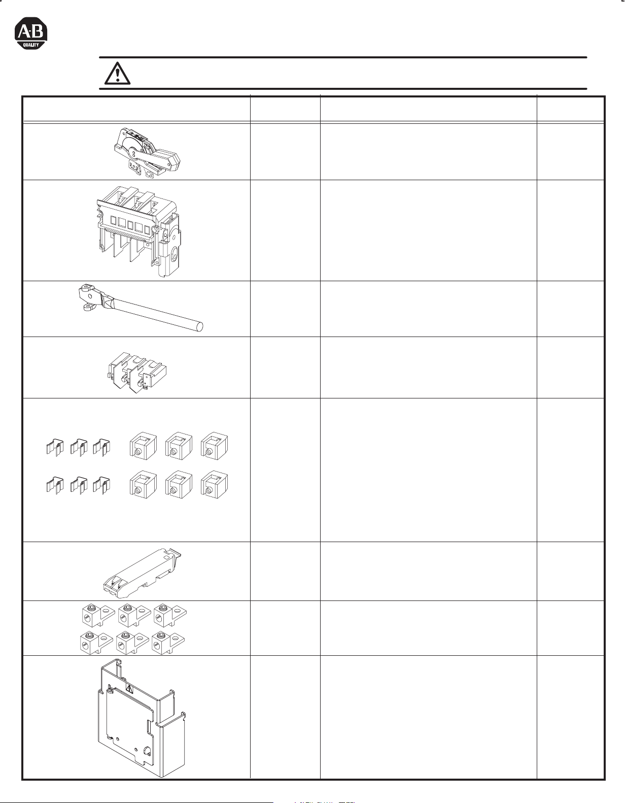
Components Cat No. Description
1494F-M1
1494F-P1
1494F-S1
1494V-DS30
1494V-DS60
1494V-DS100
1494V-DS200
1494V-RA3
1494V-RA4
1494V-FS30
1494V-FS60
1494V-FS100
1494V-FS200
5-1/2" Painted Metal Handle
5-1/2" Molded Handle
5-1/2" Stainless Steel Handle
30 Amp Switch
60 Amp Switch
100 Amp Switch
200 Amp Switch
Standard Connecting Rod
Enclosure Working Depth: 6-3/4" to 9-1/8"
Extended Connecting Rod
Enclosure Working Depth: 9-1/8" to 21-5/8"
30 Amp Fuse Block
60 Amp Fuse Block
100 Amp Fuse Block
200 Amp Fuse Block
Switch Rating
(Amps)
30...200
30
60
100
200
30...200
30
60
100
200
1401-N41
1401-N42
1401-N43
1401-N44
1401-N45
1401-N50
1401-N51
1401-N52
1401-N53
1401-N54
595-A
595-B
(Included)
1494R-N1
1494R-N2
1494R-N3
1495-N59
Fuse Clip, Class H, 30A - 250V
Fuse Clip, Class H,J, 30A - 600V,
Class H, 60A-250V
Fuse Clip, Class H,J, 60A - 600V
Fuse Clip, Class H,J, 100A-250V, 100A-600V
Fuse Clip, Class H,J, 200A-250V, 200A-600V
Fuse Clip, Class R, 30A - 250V
Fuse Clip, Class R, 30A - 600V, 60A-250V
Fuse Clip, Class R, 60A - 600V
Fuse Clip, Class R, 100A - 250V, 100A-600V
Fuse Clip, Class R, 200A-250V, 200A-600V
(1) N.O. Auxiliary Contact
(1) N.C. Auxiliary Contact
Lug Connector: Wire Size #14 . . . #8 AWG
Lug Connector: Wire Size #14 . . . #4 AWG
Lug Connector: Wire Size #14 . . . #1/0 AWG
Lug Connector: Wire Size #6 . . . #4/0 AWG
Fuse Cover with Door
(only for Right-Hand Installation)
30
30 - 60
60
100-200
100-200
30
30 - 60
60
100-200
100-200
30...200
30
60
100
200
30...100
1495-N60
Fuse Cover with Door
(only for Right-Hand Installation)
200
Page 2
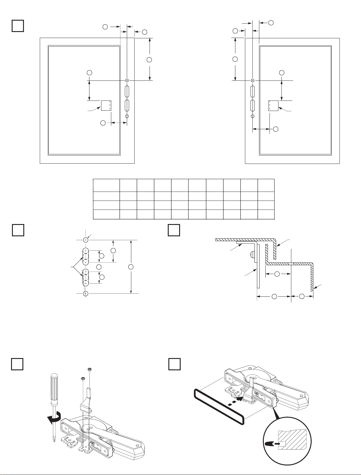
Handle Installation
Locate Handle
1
C
B
B
C
Drill Handle Holes
2
E
Door Catch
Mounting
Bracket
D
Right Hand Flange
NEMA
SIZE
30A, 60A
100A
200A
(2) .265 Dia. Holes
A
(min)
4 - 5/8"
5 - 13/16"
10 - 1/8"
B
(min)
29/32"
29/32"
29/32"
A
A
E
Door Catch
Mounting
D
Bracket
Left Hand Flange
D
E
F
G
H
C
(max)
1 - 3/32"
1 - 3/32"
1 - 3/32"
1 - 5/8"
1 - 5/8"
1 - 5/8"
Locate Door Catch
3
2 - 11/32"
2 - 11/32"
2 - 11/32"
4 - 11/16"
4 - 11/16"
4 - 11/16"
1 - 9/16"
1 - 9/16"
1 - 9/16"
J
1"
7/8"
1"
7/8"
1"
7/8"
Enclosure Door
Door Catch
Mounting Bracket
Door Catch
C
To make slot drill
(3) 1/2" diameter holes
and remove burrs
G
H
J
H
F
Enclosure
D
B
Base
Notes:
A) Enclosures with a Flange Thickness less than 3/16" use dimensions above.
B) Enclosures with a Flange Thickness 3/16" and greater use dimensions in Mounting Kit 1494V-H3.
C) Multi-Door Enclosures use dimensions in Channel Support Kit 1494V-H4, if handle is mounted atop channel.
D) The door catch mounting bracket is provided with projections for welding; however, holes can be drilled in the bracket using the
projections for locating hole centers. After proper location, use the bracket as a template and drill corresponding holes in the
enclosure door. Fasten the bracket with hardware supplied by user. If properly assembled, the hardware should not be accessible for
tampering with by unauthorized personnel.
Install Defeater Lever
4
7-11 lb-in
Install Gasket
5
(2)
Page 3
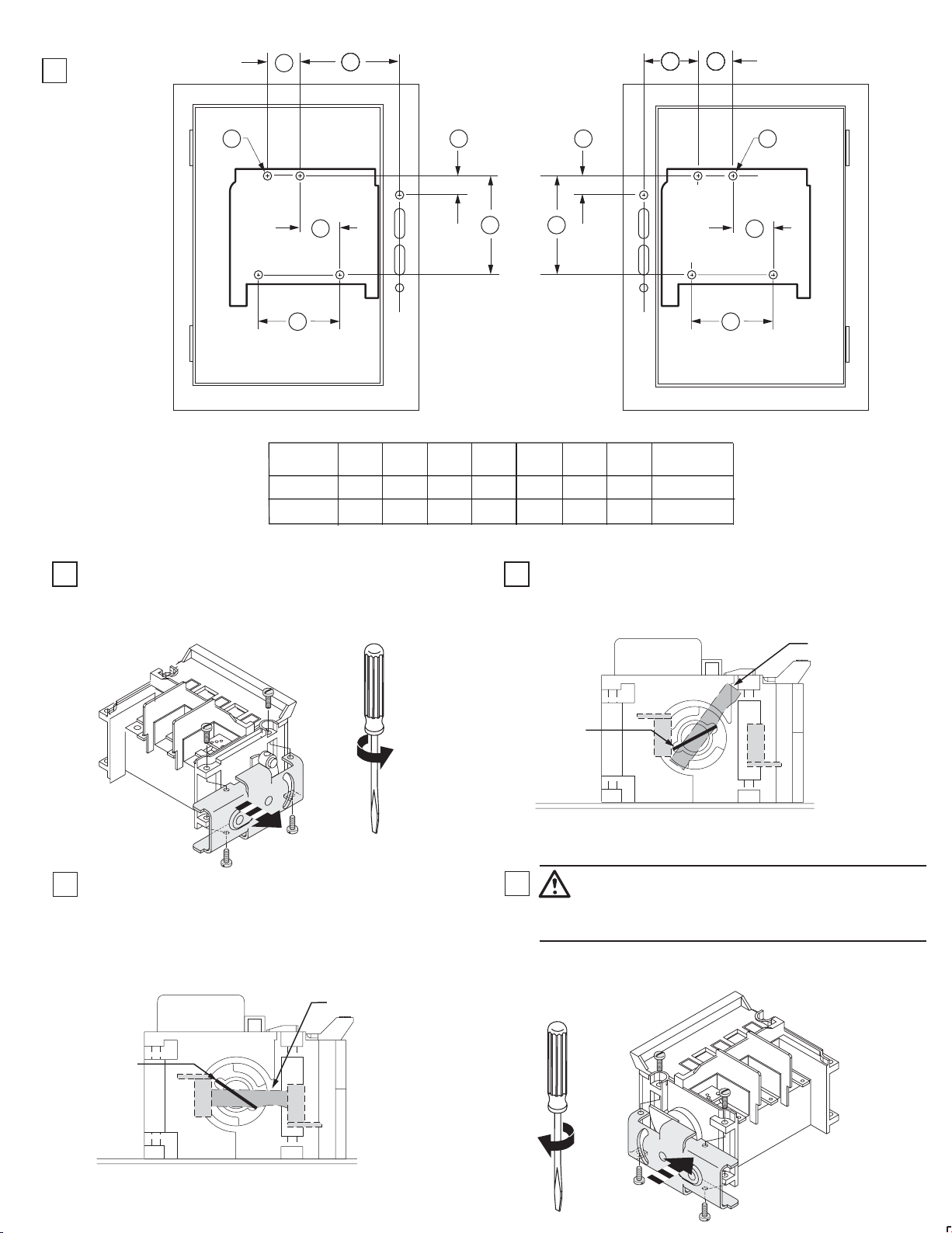
Disconnect Switch Installation
Locate
1
Disconnect
Switch
CC
AAAAAAAAAAAA
AAAAAAAAAAAAAAAAAAAAAAGG AAAAAAAAAAAAAAAAAAAAAACC
HH
EE
FF
BB BB
DD DD
Right Hand Flange Left Hand Flange
SIZE
30A, 60A,100A
200A
AA BB CC DDNEMA
3 - 29/64" 1 - 27/32" 1 - 31/32" 4 - 21/64" 1" 3 - 15/16"
3 - 53/64" 2 - 63/64" 2 - 23/64" 4 - 59/64" 1 - 7/64" 4 - 23/32" (4) 1/4-20 2 - 61/64"
Conversion from Right-Hand Installation to Left-Hand Installation
With the disconnect switch in the "OFF" position, (blades visible)
2 3
loosen and remove the (4) screws.
Remove the drive mechanism from the right-hand side of the
disconnect switch.
Save the (4) 1/4-20 pan head screws shown below.
HH
EE
FF
EE FF GG HH
2 - 37/64"
(4) #10-32
Insert the rectangular metal plate provided with the hardware kit
into the crossbar end slot on the right-hand side as shown below.
Movable
Blades
Rotate the crossbar assembly in a clockwise direction to the
4
"ON" position (blades fully engaged - not visible).
(Use any convenient adjustable wrench or pliers to aid in
rotating the crossbar & moveable blades.)
Moveable Blades
Rectangular
Metal Plate
Rectangular
Metal Plate
5
ATTENTION: Do not attempt to change the position of the
drive mechanism after removal from the disconnect assembly.
Use the rectangular metal plate to rotate the crossbar from the
"OFF" position to the full "ON" positiom.
Remove the rectangular metal plate and discard, (not required for
switch operation.)
Position the drive mechanism assembly as shown below and install
the (4) screws.
40-60 lb-in
(3)
Page 4

Trailer Fuse Block and Fuse Clip Installation
Install Trailer Block
1
Q
Install Fuse Clips
2
30A ....... 60A 100A ....... 200A
R
Y
Z
W
V
X
40 lb-in
R
Install Wire Lugs to Terminals
3
2
1
S
4
Install Wire to Lugs
4
T
3
10 - 15 lb-in
1
2
(4)
Page 5

Switch Fuse Fuse Block Clip Block Mtg. Screw Mtg. Screw Termina l Lug
Trailer Fuse Fuse Fuse Block Fuse Clip Lug to Wire to
Rati ng Ra ting F use Cata log Cata log V W X Y Z Mounting Torque Torque Torque Torque
(Amps) Amps/Volts Class Number Number inches inches inches inches inches Hole lb-ins. lb-ins. lb-ins. lb-ins.
30A, 250V 1494V-FS30 1401-N41 2-1/4 1-13/16 1-31/32 31/32 9/16
30A, 250V 1494V-FS30 1401-N50 2-1/4 1-13/16 1-31/32 31/32 9/16
30A, 600V 1494V-FS30 1401-N42 2-1/4 1-13/16 1-31/32
30A, 600V 1494V-FS30 1401-N42 2-1/4 1-13/16 1-31/32
30
30A, 600V 1494V-FS30 1401-N42 2-1/4 1-13/16 1-31/32
30A, 60 0V 1494V-FS30 1401-N51 2-1/4 1-13/16 1-31/32
60A, 250V 1494V-FS30 1401-N42 2-1/4 1-13/16 1-31/32
60A, 250V 1494V-FS30 1401-N51 2-1/4 1-31/32
60A, 600V 1494V-FS30 1401-N43 2-1/4 1-31/32
60A, 600V 1494V-FS30 1401-N43 2-1/4 1-31/32
60A, 600V 1494V-FS30 1401-N52 2-1/4 1-31/32
H
R
3-47/64
31/32
31/32 9/16J
3-47/64
1-47/64
1-47/64
4-15/64
1-3/32
4-15/64
3-21/64
9/16
3-21/64
1-11/32
1-11/32
3-27/32
23/32
3-27/32
#10-32
3030
H
J
R
H
R
H
J
R
1-13/16
1-13/16
1-13/16
1-13/16
Term
Screw
#10-322030
60A, 250V 1494V-FS60 2-1/4 1-31/32
60A, 600V 1494V-FS60 2-1/4 1-31/32
60A, 600V 1494V-FS60 2-1/4 1-31/32
60A, 600V 1494V-FS60 2-1/4 1-31/32
60A, 600V
60A, 600V
60A, 600V 1494V-FS60 2-1/4 1-31/32 1-21/64
60
60A, 600V
60A, 600V 1494V-FS60 2-1/4 1-31/32 11/16
60A, 600V 1494V-FS60 2-1/4 1-31/32 3-53/64R 1401-N52 1-13/16 4-15/64
100A, 250V
100A, 250V
100A, 600V
100A, 600V 1494V-FS6 0 2-1/4 1-31/32 2-9/16J 1401-N44 2-31/32 1-13/16
100A, 60 0V
**
60A, 600V 1494V-FS100 1401-N43 2-1/ 8 1-31/32 6-17/64
60A, 600V
** 1494V-FS100 1401-N43 2-1/8 1-11/16 1-31/32 4-63/64 J 5-3/8
**
60A, 600V
100A, 250V 1494V-FS100 1401-N44 2-1/8 1-11/16 1-31/32H 4-5/8 4-15/64
100A, 250V 1494V-FS100 1401-N53 2-1/8 1-11/16 1-31/32R 4-5/8 4-15/64
100
100A, 250V 1494V-FS100 1401-N44 2-1/8 1-11/16 1-31/32H 6-5/8 6-15/64
100A, 600V 1494V-FS100 1401-N44 2-1/8 1-11/16 1-31/32J 3-3/8 2-63/64
100A, 600V 1494V-FS100 1401-N53 2-1/8 1-11/16 1-31/32
*
200A, 600V 1494V-FS100 1401-N45 7/16 1-11/16 1-31/32J 4-1/8 3-47/64 #10-32 9030
H
R
H
J
R
1494V-FS60 2-1/4 1-31/32
H
1494V-FS60 2-1/4 1-31/32 1-21/64
R
H
1494V-FS60 2-1/4 1-31/32 3-53/64
J
1494V-FS60 2-1/4 1-31/ 32 3-27/32
H 1401-N44 1-13/16 4-1/4
1494V-FS60 2-1/4 1-31/ 32 3-27/32R 1401-N53 1-13/16 4-1/4
H
1494V-FS60
R
1494V-FS60 2-1/4 1-31/32 5-13/16
H
1494V-FS100
R
R
1401-N41
1401-N50
1401-N42
1401-N42
1401-N51
1401-N42
1401-N51
1401-N43
1401-N43
1401-N44
1401-N53
1401-N52 2-1/ 8 1-11/16 1-31/32 6-17/64
1-13/16
1-13/16
1-13/16
1-13/16
1-13/16
1-13/16
1-13/16
1-13/16
1-13/16
1-13/16
2-1/4 1-31/32 5-13/16
1-13/16
1-11/16
31/32
31/32
3-47/64
31/32
3-47/64
1-47/64
1-47/64
4-15/64
1-3/32
6-7/32
6-7/32
6-5/8
6-5/8
6-5/8
9/16
9/16
3-11/32
1-11/32
3-11/32
6-15/64
#10-32
#10-32
#10-32
#10-32
3030
#1/4-284550
30
30
20
30
#5/16/2415090
2030
100A, 600V 1494V-FS200 1401-N44 1-41/64 1-1/4 2-23/64
100A, 600V 1494V-FS200 1401-N44 1-41/64 1-1/4 2-23/64
100A, 600V 1494V-FS200 1401-N53 1-41/64 1-1/4 2-23/64
200A, 250V 1494V-FS200 1401-N45 1-41/64 1-1/4 2-23/64
200A, 250V 1494V-FS200 1401-N54 1-41/64 1-1/4 2-23/64R 7-27/64 5-43/ 64
200
200A, 600V 1494V-FS200 1401-N45 1-41/64 1-1/4 2-23/64H 9-59/64 8-13/ 64
200A, 600V 1494V-FS200 1401-N45 1-41/64 1-1/4 2-23/64
200A, 600V 1494V-FS200 1401-N54
*
400A, 600V 1494V-FS200 1401-N46 1-41/64 1-1/4 2-23/64 1/4-20J 8-17/32 6-13/64 17540
*
FUSE BOLTS DIRECTLY TO THE SWITCH AND FUSE BLOCK TERMINALS
H
J
R
H
J
1-41/64 1-1/4 2-23/64R 9-59/64 8-13/64
**FUSE ADAPTER KIT CATALOG NUMBER 1401-N170 REQUIRED.
8-35/64
5-19/64
8-35/64
7-27/64
6-3/64
(5)
6-53/64
3-37/64
6-53/64
5-43/64
4-21/64
1/4-20
40
20 #3/8-24275175
Page 6

Connecting Rod Installation
1
Connecting
N
Enclosure
Working Depth
(Flange to
Mounting Plate)
Right Hand Operation
Install connecting rod in mechanism and
2
thread in clockwise (12) full turns
Standard
Extended
Rod
Catalog Number
1494V-RA3
1494V-RA4
N - 3"
Front
"N"
Min. Max.
6-3/4" 9-1/8"
9-1/8" 21-5/8"
Place the disconnect handle in the "OFF" position. Insert the
3
ears of rod into the primary link of the handle and install the
hitch pin as shown below
Connecting Rod Adjustment Procedure
"ON" Position
4 5
a) Move disconnect handle to the "ON" position.
b) If switch does not fully close, return handle to "OFF"
position.
c) Remove hitch pin and disengage the connectiong rod from the
primary link.
d) Turn connecting rod counter-clockwise (1) full turn.
e) Re-engage connecting rod in primary link of handle, insert
hitch pin and re-test
f) Repeat 4a - 4e as necessary.
(6)
"OFF" Position
g) Move disconnect handle to the "OFF" position.
h) If switch does not fully open, return handle to "ON"
position.
j) Remove hitch pin and disengage the connectiong rod from
the primary link.
k) Turn connecting rod clockwise (1) full turn.
l) Re-engage connecting rod in primary link of handle, insert
hitch pin and re-test
m) Repeat 5g - 5l as necessary.
Page 7

Left Hand Operation
Install connecting rod in mechanism and thread in
6
clockwise (9) full turns.
Connecting Rod Adjustment Procedure
"ON" Position
8 9
a) Move disconnect handle to the "ON" position.
b) If switch does not fully close, return handle to "OFF"
position.
c) Remove hitch pin and disengage the connectiong rod
from the primary link.
d) Turn connecting rod counter-clockwise (1) full turn.
e) Re-engage connecting rod in primary link of handle,
insert hitch pin and re-test
f) Repeat 4a - 4e as necessary.
7
Place the disconnect handle in the "ON" position. Insert the
ears of rod into the primary link of the handle and install the
hitch pin as shown below.
"OFF" Position
g) Move disconnect handle to the "OFF" position.
h) If switch does not fully open, return handle to "ON" position.
j) Remove hitch pin and disengage the connectiong rod from the
primary link.
k) Turn connecting rod clockwise (1) full turn.
l) Re-engage connecting rod in primary link of handle, insert
hitch pin and re-test
m) Repeat 5g - 5l as necessary.
Auxiliary Contact Installation
Important: Before installing auxiliary contact, disconnect switch must be in "Off" position.
1 2
Align
Arrows
(7)
Click
Page 8
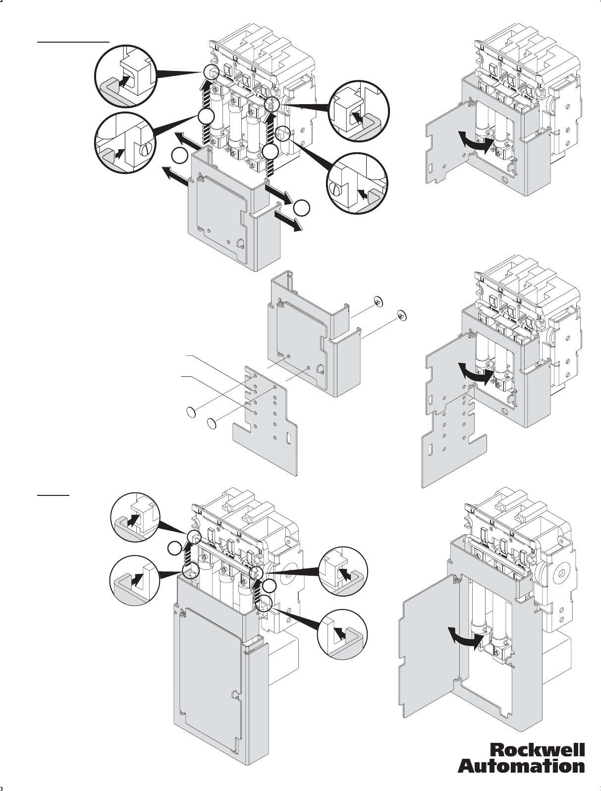
Fuse Cover Installation
30 A ... 100 A
2
30 A ... 100 A Non-Fused
30 A, 250 V, Class H, R Fuses
30 A, 600 V, Class J Fuses
60 A, 250 V, Class H, R Fuses
60 A, 600 V, Class J Fuses
100 A, 600 V, Class J Fuses
100 A, 600 V, Class H, R Fuses
30 A, 600 V, Class H, R Fuses
60 A, 600 V, Class H, R Fuses
100 A, 250 V, Class H, R Fuses
200 A, 600 V, Class J Fuses
1
2
1
200 A
200 A Non-Fused
100 A, 250 V, Class H, R Fuses
100 A, 600 V, Class H, J, R Fuses
200 A, 250 V, Class H, R Fuses
200 A, 600 V, Class H, J, R Fuses
400 A, 600 V, Class J Fuses
42052-064-01 (1)
Printed in U.S.A.
2
2
 Loading...