

Page 1

Bulletin 1494V Variable Depth Disconnect Switch Installation Instructions
(Cat 1494V-DS400; -DSX400 - Series D)
ATTENTION: To prevent electrical shock, disconnect from power source before installing or servicing. Follow
NFPA 70E requirements. Install in suitable enclosure. Keep free from contaminants.
ATTENTION: The following procedures are critical to the proper operation of the disconnect handle and switch.
Failure to follow these steps can result in damage to the equipment and/or serious injury or death to the operator.
Table of Contents Page
Quick Installation Guide 2
Disconnect Switch Installation
-
- Disconnect Handle Installation
- Cutting Connecting Rod
Quick Installation Guide (continued) 3
-
Connecting Rod Installation
Connecting Rod Adjustment Procedure 4
Enclosure Without Handle Cutout 5
Locate Handle
-
- Drill Handle Holes
Door Catch Mounting Bracket Installation 6
Disconnect Switch Installation 7
Locate Disconnect Switch
-
- Install Disconnect Switch
- Assemble and Install Line Terminal Guard
Trailer Fuse Block Installation 8
Phase Barrier Replacement and Terminal Adapter Installation 9
Fuse Clip Installation 10
Bulletin 1494V Disconnect Switch Kit 11
Bulletin 1494V Disconnect Switch Kit Optional Accessory List 12
Page 2
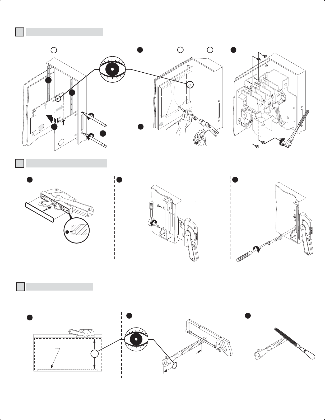
QUICK INSTALLATION GUIDE
Disconnect Switch Installation (Right hand installation shown. For left hand installation follow similar procedure.)
1
Use template D to locate handle holes on mounting plate.
4
2
E
L
O
H
E
L
D
N
A
P H
O
T
MEASURE TO
INSIDE
INSIDE OF THE
HOLD FLUSH
TO
OF ENCLOSURE
TOP
TAPE
D
OF ENCLOSURE
LE
O
H
LE
D
N
A
H
TOM
T
O
B
3
MEASURE T
INSIDE OF
OF ENCLOSURE
TOP
D
Disconnect Handle Installation
2
Install gasket.
1
O
THE
HOLD FLUSH
TO
OF ENCLOSURE
P
O
T
INSIDE
T
T
O
B
11
Overlay template E (400 A) over D .
5
5 - 1/2
5
2
TOP
H
S
U
E
FL
O
D
SID
T
E
L
E
IN
R
O
E
R
HE
H
R
T
SU
6-1/2
TO
U
SU
O
S
A
L
OF
E
O
11
E
)
1
(
1
0
8
5
-1
.
2
5
.A
.S
20
U
4
in
d
e
t
6
rin
P
M
IN
O
P
Switch Mounting Holes
O
T
Center punch and drill
forming (TAP-T
A
c
s
i
D
U
(
E
L
C
ID
(4) 11/32" holes for thread
s provided with switch
N
S
w
O
F E
ITE) scre
4 - 3/4
c
o
L
le
o
H
h
c
it
f
w
le
S
r
t
o
f
c
e
e
n
id
n
o
s
e
it
s
o
p
p
RIGHT Hand Installa
o
e
s
C
N
E
F
BOTT
)
A
0
0
4
(
e
t
la
p
m
e
)
T
n
n
tion
o
io
i
t
t
a
a
ll
a
t
s
in
d
n
a
h
t
7
Center punch
and drill (4) holes
for 5/16-18 thread forming
screws provided with switch.
9/32" Dia.
Install handle and spring bracket.
2 3
Install disconnect switch.
90 -130 lb-in
Install defeater lever.
60-80 lb-in
IMPORTANT:
Apply grease to O-Ring
7-11 lb-in
to retain into handle groove.
Cutting Connecting Rod (Cut (2) Connecting Rods; first rod connects the handle to the switch, second rod provides
3
stiffening for the enclosure flange)
Measure working depth of enclosure.
1
Mounting
Plate
Enclosure
Working Depth
(Inside Flange
of Enclosure to
Mounting Plate)
Measure, mark and
2
cut (2) connecting rods.
N
N minus 3-3/4"
Remove burrs.
3
(2)
Page 3
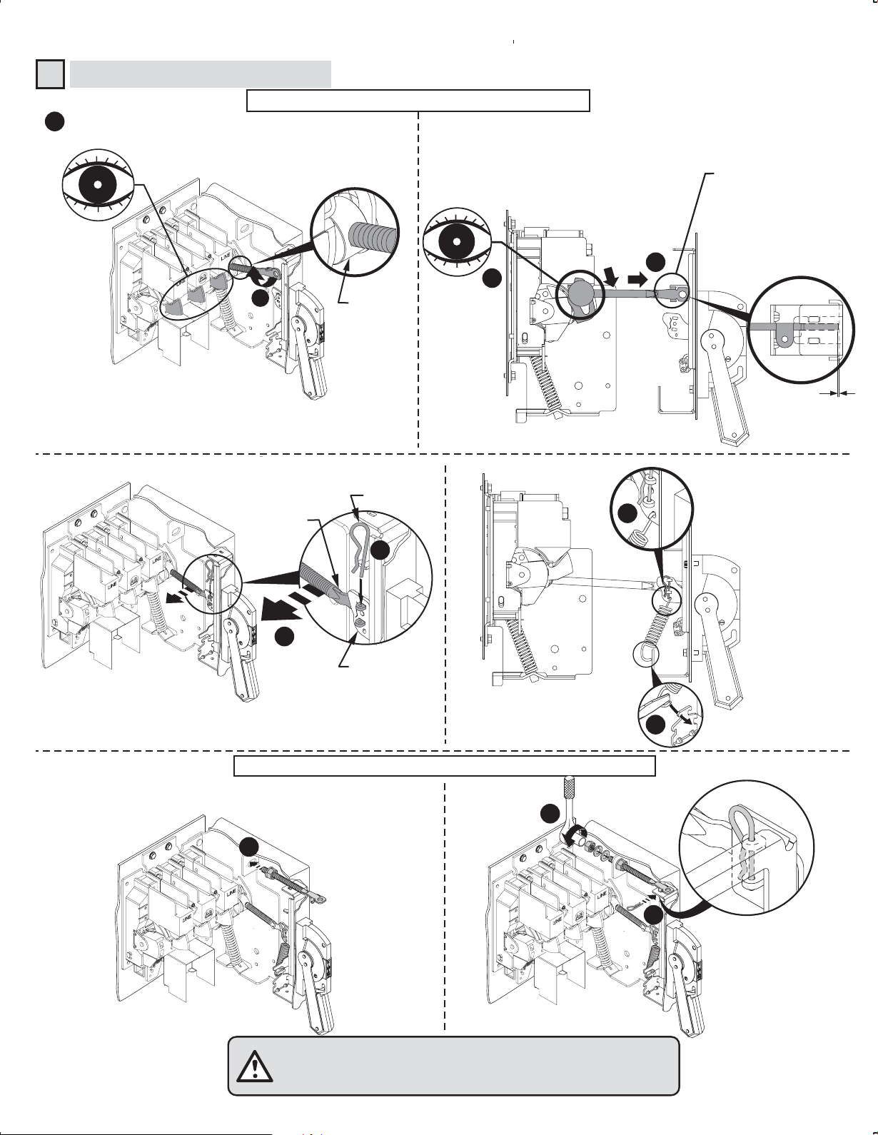
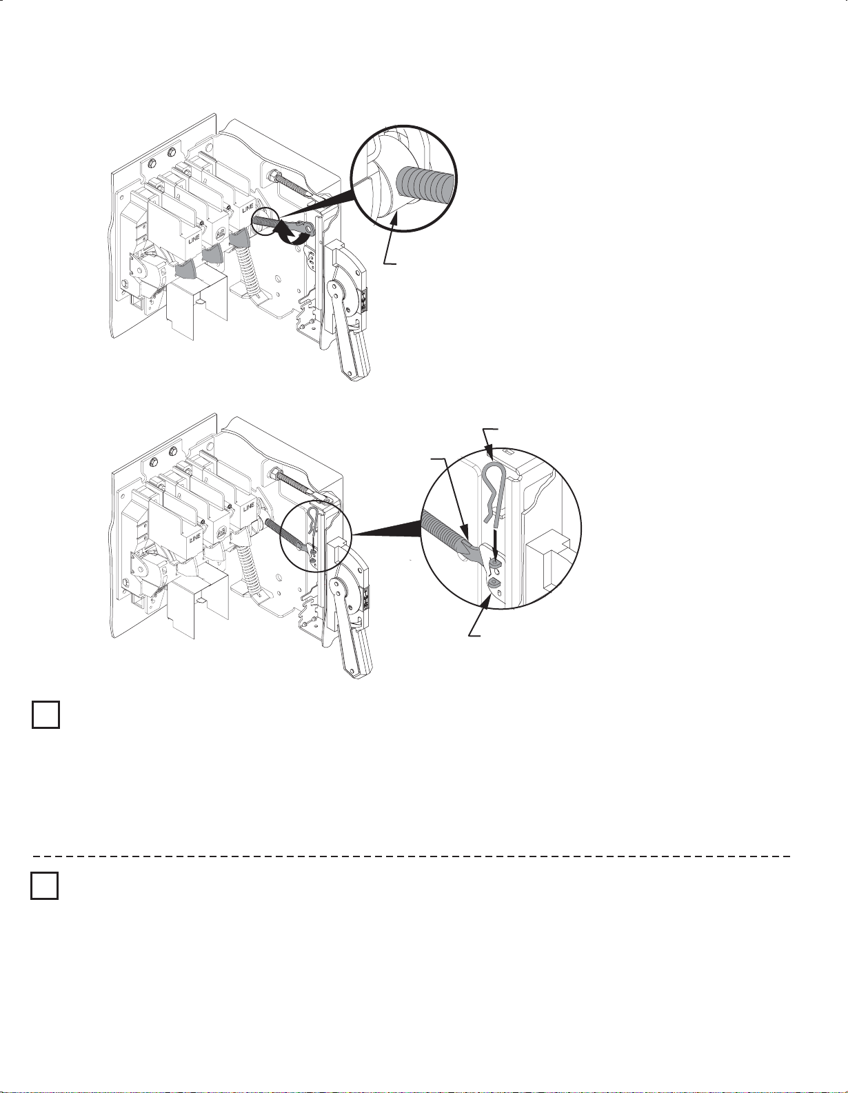
QUICK INSTALLATION GUIDE (CONTINUED)
Connecting Rod Installation
4
First rod connects the handle to the switch
Verify that disconnect switch and handle are in "OFF"
1
position. (Switch blades will be visible)
3
2
Drive Bar
Pull rod up and verify if
rod is touching bottom
of spring bracket. (If
not, rotate rod until it
touches spring bracket)
4
Rotate connecting rod into
drive bar 16 turns.
Hitch Pin
Connecting
Rod
7
6
5
Primary Link
Second rod provides stiffening for the enclosure flange
Zero
Clearance
8
11
9
ATTENTION: CHECK FOR PROPER OPERATION
(3)
150 - 200 lb-in
10
Page 4
Connecting Rod Adjustment Procedure
Drive Bar
Hitch Pin
"ON" Position
1
Move disconnect handle to the "ON" position.
➊
If switch does not fully close, return handle to "OFF" position.
➋
Remove link spring hitch pin and disengage the connectiong rod from the primary link.
➌
Turn connecting rod counter-clockwise (1 or more) full turns.
➍
Re-engage connecting rod in primary link of handle, insert hitch pin and re-test
➎
Repeat ➊ - ➎ as necessary.
➏
Re-install link spring
➐
Connecting
Rod
Primary Link
"OFF" Position
2
Move disconnect handle to the "OFF" position.
➊
If switch does not fully open, return handle to "ON" position.
➋
Remove hitch pin and link spring, then disengage the connectiong rod from the primary link.
➌
Turn connecting rod clockwise (1 or more) full turns.
➍
Re-engage connecting rod in primary link of handle, insert hitch pin and re-test.
➎
Repeat ➊ - ➎ as necessary.
➏
Re-install link spring
➐
(4)
Page 5

Enclosure without Handle Cutout
● Enclosures with a Flange Thickness less than 3/16" use dimensions below to install disconnect handle.
● Enclosures with a Flange Thickness 3/16" and greater use dimensions in Alternate Mounting Kit 1494V-H6 to install disconnect
handle.
Locate Handle
1
1 - 1/8" Max.
1 - 3/8" Min.
1 - 3/8" Min.
1 - 1/8" Max.
Drill Handle Holes
2
14 - 3/8" Min.
Top Handle Hole
14 - 3/8" Min.
Right Hand Flange Left Hand Flange
(2) .328 Dia. Holes
Top Handle Hole
5/16"
Square corners or up to 1/4" radius
1/4"
(5)
1/2"
5 - 1/2"
6 - 1/2"
Page 6

Door Catch Bracket Installation
Right hand installation shown (for left hand installation follow similar procedures)
Door Catch Mounting Bracket:
● Provided with projections for welding.
● Projections can also be used as a guide for drilling holes.
● Can be used as a template to drill corresponding holes in the enclosure door.
● User to supply the hardware for fastening the bracket.
● Fasteners must provide the degree of ingress protection for the environmental rating of the enclosure.
● The bracket hardware must be inaccessible to unauthorized personnel.
● Dimension K (3/4" to 1")
● When using large disconnect handle kit only (1494F-M2 or -S2), use door catch provided with handle kit.
● When using large disconnect handle kit and small door hardware kits (1494V-L1, -LL1, -L2 or -LL2), use door catch
provided with door hardware kit.
Dimension K (1-1/8" to 1-3/8")
● When using large disconnect handle kit only (1494F-M2 or -S2), use door catch (40492-080-02) which can be ordered
from factory.
● When using large disconnect handle kit and large door hardware kits (1494V-L3 or -LL3), use door catch provided with
door hardware kit.
Door Catch
Mounting Bracket
Top
Enclosure Door
Door Catch
Mounting Bracket
Door Catch
C
E
TOP VIEW
NEMA
SIZE
400A
B
A
22 - 37 lb-in
Flange
Thickness
C
D
B
Enclosure Dimensions
C
A
(min)
14 - 3/8"
B
(max)
(min)
1 - 3/8"
Top Handle Hole
1 - 5/8"
Door Catch
K
Enclosure
Base
DE
3 - 3/4"1 - 1/8"
C
B
A
E
Door Catch
Mounting
Bracket
D
D
Door Catch
Mounting
Bracket
Right Hand Flange Left Hand Flange
(6)
Page 7

Disconnect Switch Installation
Locate Disconnect Switch
1
CC
AAAAAAAA
AA
AAAAAAAA
CCEE
FF
HH
GG
BBBB
Top Handle Hole
GG
FF
HH
Right Hand Flange Left Hand Flange
Panel Mounting Dimensions
Switch
Size
400A
AA BB CC DD
5" 5-1/2" 2" 11" 5" 4-3/4" 1-3/8"9/32" Dia.
EE
(4 Mounting Plate Holes)
FF
GG HH
DDDD
Install Disconnect Switch Assemble and Install Line Terminal Guard
2 3
LINE TERMINAL GU
1
90 - 130 lb-in
ARD
LINE TERMINAL GUARD
2
(7)
Page 8

Trailer Fuse Block Installation (Switch Rating 400A)
Trailer Fuse Block Location
1
Note: Not required for non-fusible disconnect switch applications.
400 Amp Trailer Fuse Block (1494V-FS400)
Amps Voltage Class Fuse
200
200
200
200
400
400
400
400
A
250
600
600
600
250
600
600
600
H/R
H/R
J
HRCII-C
H/R
H/R
J
HRCII-C
A
7-11/16"
10-3/16"
6-3/8"
6-3/8"
8-11/16"
11-11/16"
7-3/16"
8-11/16"
Clip
16-22
-
22
37
Torque (lb-in)Fuse
Fuse
Block
90-130
Lug to
Terminal
-
200 275-305
175
Wire
into Lug
Install Trailer Fuse Block
2
4 - 3/4"
90 - 130 lb-in
(8)
Page 9

Phase Barrier Replacement Kit (Switch Rating 400A)
1494F-PH5
1
20 - 30 lb-in
3
2
CLICK
4
Terminal Adapter Installation - Conversion from Fusible to Non-Fusible (Switch Rating 400A)
90 - 110 lb-in
1
35 - 50 lb-in
3
175 - 200 lb-in
2
(9)
Page 10

Fuse Clip Installation (Switch Rating 400A)
Switch for Right Hand Mechanism
1
200A Fuse Clips
400A Fuse Clips
16 - 22 lb-in
22 - 37 lb-in
Switch for Left Hand Mechanism
1
200A Fuse Clips
400A Fuse Clips
2
2
16 - 22 lb-in
22 - 37 lb-in
1
1
Switch for Right Hand Mechanism
2
200A Fuse Clips
400A Fuse Clips
23 - 37 lb-in
40 - 55 lb-in
1
Switch for Left Hand Mechanism
2
2
1
2
200A Fuse Clips
400A Fuse Clips
23 - 37 lb-in
40 - 55 lb-in
(10)
Page 11

Bulletin 1494V Disconnect Switch Kit
Disconnect Kit
Switch
Handle
Catalog Number and Description
Switch with Right Hand Mechanism
1494V-DS400 (400A)
Switch with Left Hand Mechanism
1494V-DSX400 (400A)
1494F-M2 (7-1/2" Painted Metal) (400A / 600A)
1494F-S2 (7-1/2" Stainless Steel) (400A / 600A)
Connecting
Rod
Fuse
Block
Fuse
Clips
1494V-RB3 (Standard) (400A)
Enclosure Working Depth: 9-1/2" to 10"
1494V-RB4 (Extended)(400A)
Enclosure Working Depth: 9-1/2" to 23"
1494V-FS400 (400A)
1401-N45 (Class H, J, 200A-250V, 200A-600V)
1401-N46 (Class H, J, 400A-250V, 400A-600V)
1401-N54 (Class R, 200A-250V, 200A-600V)
1401-N55 (Class R, 400A-250V, 400A-600V)
(11)
Page 12

Bulletin 1494V Disconnect Switch Optional Accessory List
Optional Accessories
(Installation Instructions
Included with Accessory Kits)
Electrical
Interlock
Catalog Number and Description
Switch with Right Hand Mechanism
1495-N43 (1-N.O./N.C.)
1495-N44 (2-N.O./N.C.)
Switch with Left Hand Mechanism
1495-N41 (1-N.O./N.C.)
1495-N42 (2-N.O./N.C.)
Auxiliary
Contact
Auxiliary
Contact
Adapter Kit
Lug
Connectors
Phase
Barrier
1495-N8 (1-N.O.) (400A)
1495-N9 (1-N.C.) (400A)
1495-N25 (400A)
(Required only for Switch with Left Hand
Mechanism)
1494R-N14
(CU Wire Size 2 - #1/0 -250 MCM) (400A)
1494R-N15
(CU Wire Size #4 . . 500 MCM) (400A)
1494F-PH5 (400A)
42052-154-01 (2)
Printed in U.S.A.
Fuse
Cover
with Door
Switch
Rating
400A ----
400A ----
400A
Fuse
Class
Non-Fusible 1495-N68➀
Non-Fusible 1495-N63➁
H, J, R400A
H, J, R
➀ Switch with right hand mechanism
➁ Switch with left hand mechanism
Fuse Clip
Rating
250V 600V
200A
400A
200A
400A
----
----
200A
400A
200A
400A
Cat No.
1495-N68➀
1495-N63➁
 Loading...