

Page 1

Bulletin 1494V Variable Depth Disconnect Switch Installation Instructions
(Cat 1494V-DS30; -DSX30 - Series D; 1494V-DS60; -DSX60 - Series D)
(Cat 1494V-DS100; -DSX100 - Series D; 1494V-DS200; -DSX200 - Series D)
WARNING
WARNING
To prevent electrical shock, disconnect from power source before installing or servicing. Follow
NFPA 70E requirements. Install in suitable enclosure. Keep free from contaminants.
The following procedures are critical to the proper operation of the disconnect handle and switch.
Failure to follow these steps can result in damage to the equipment and/or serious injury or death to the
operator.
Table of Contents Page
Quick Installation Guide 2
Disconnect Switch Installation
-
- Disconnect Handle Installation
- Cutting Connecting Rod
Quick Installation Guide (continued) 3
Connecting Rod Installation
-
Connecting Rod Adjustment Procedure 4
Enclosure Without Handle Cutout 5
- Locate Handle
- Drill Handle Holes
Door Catch Mounting Bracket Installation 6
Disconnect Switch Installation 7
-
Locate Disconnect Switch
- Install Disconnect Switch
- Assemble and Install Line Terminal Guard
Trailer Fuse Block Installation (30A, 60A, 100A) 8
Trailer Fuse Block Installation (200A) 9
Fuse Clip Installation and Phase Barrier Replacement (30A, 60A) 10
Fuse Clip Installation and Phase Barrier Replacement (100A) 11
Fuse Clip Installation (200A)
12
Fuse Clip Installation (Switch Rating 200A) for 400A Class J Fuses 13
Phase Barrier Replacement (200A) 14
42052-116-01 (7)
Printed in U.S.A.
Bulletin 1494V Disconnect Switch Kit 15
Bulletin 1494V Disconnect Switch Kit Optional Accessory List 16
Page 2
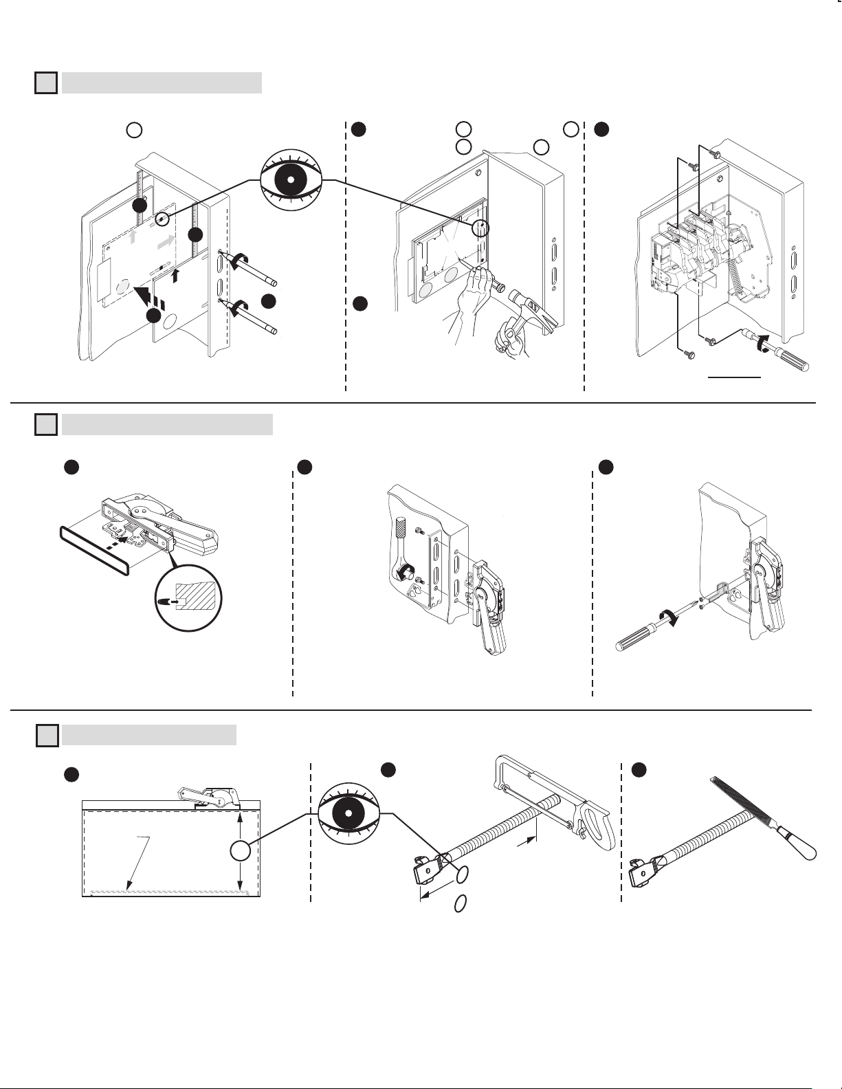
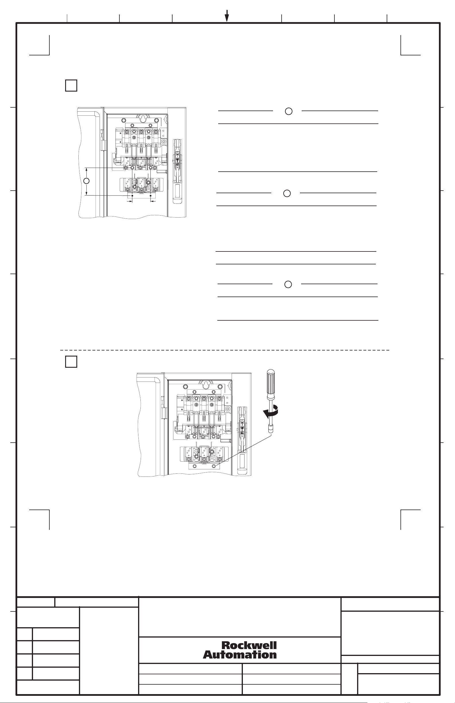
QUICK INSTALLATION GUIDE
Disconnect Switch Installation (Right hand installation shown. For left hand installation follow similar procedure.)
1
Use template A to locate handle holes on mounting plate.
4
TOP HANDLE HOLE
2
MEASURE TO
INSIDE OF THE
HOLD FLUSH
TO INSIDE
TOP OF ENCLOSURE
OF ENCLOSURE
TAPE
BOTTOM HANDLE HOLE
A
TOP OF ENCLOSURE
3
Disconnect Handle Installation
2
Install gasket.
1
MEASURE TO
INSIDE OF THE
A
HOLD FLUSH
TO INSIDE
OF ENCLOSURE
TOP
BOTT
11
Overlay template B (30 A - 100 A) over A .
5
7
Overlay template C (200 A) over A .
3 - 1/16"
TOP
2 - 1/4"
2 - 1/4"
switch
HOLD FLUSH
4 - 11/16"
TO INSIDE
MEASURE TO
INSIDE OF THE
OF ENCLOSURE
Switch Mounting Holes
TOP OF ENCLOSURE
Center punch and drill (4) 11/64" holes for
tap-tite screws provided with
5 - 1/4"
BOTT
C
A
or
B
1
6
Center punch and
drill (4) holes
for thread forming
(TAP-TITE) screws
provided with switch.
11/64" Dia. (30A - 100A)
7/32" Dia (200A)
Install handle and spring bracket.
2 3
Install disconnect switch.
23 - 37 lb-in
(30A - 100A)
40 - 60 lb-in
(200A)
Install defeater lever.
Cutting Connecting Rod
3
Measure working depth of enclosure.
1
Mounting
Plate
Working Depth
(Inside Flange
of Enclosure to
Mounting Plate)
Enclosure
30-40 lb-in
7-11 lb-in
Measure, mark and
2
cut connecting rod.
Remove burrs
3
N
N minus 3-1/8"
(30A - 100A)
N minus 3-1/4"
(200A)
(2)
Page 3
QUICK INSTALLATION GUIDE (CONTINUED)
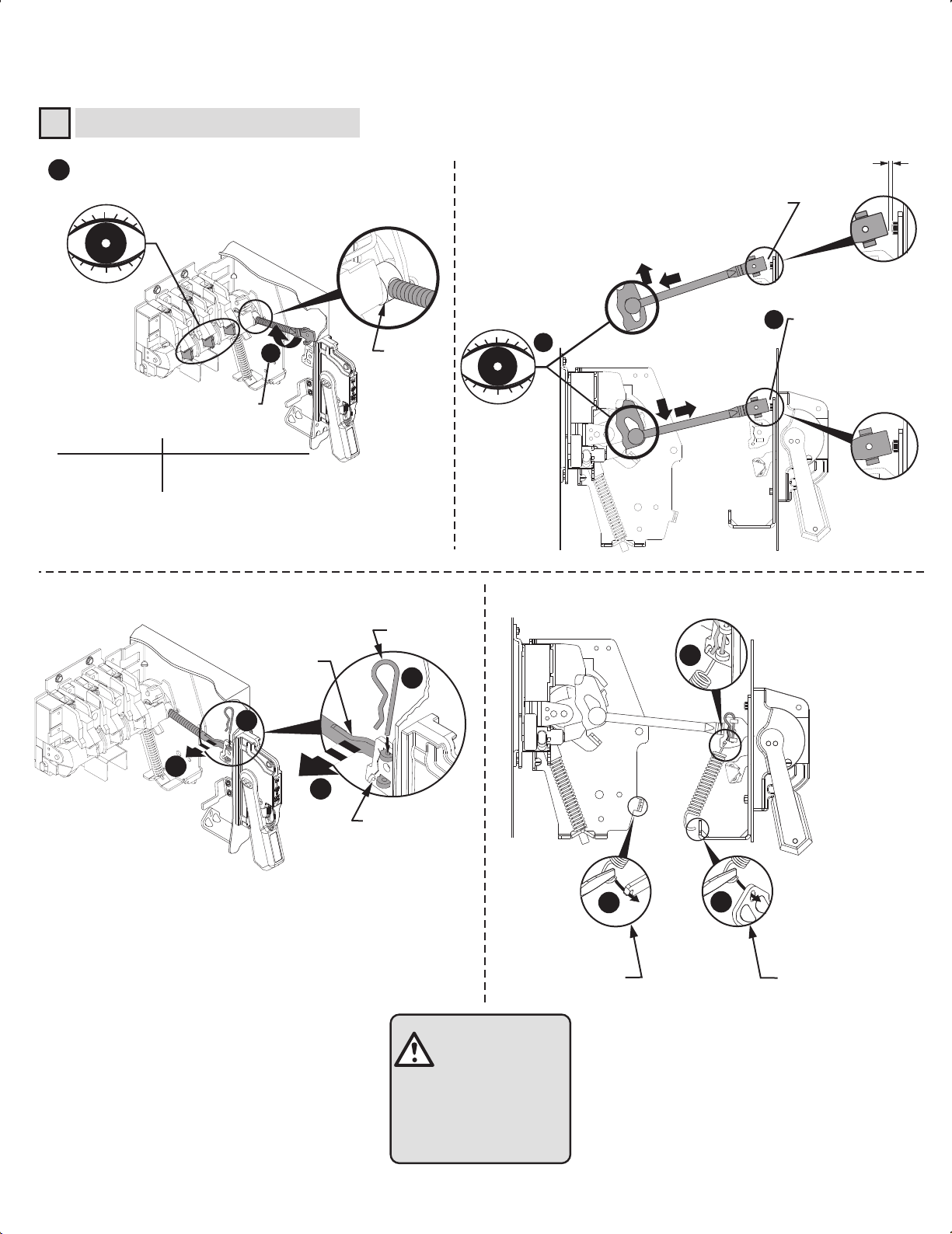
Connecting Rod Installation
4
Verify that disconnect switch and handle are in "OFF"
1
position. (Switch blades will be visible)
Drive Bar
Rotate connecting rod into
drive bar (see table).
Switch Rating
30A - 60A - 100A
200A
Full Turns Engagement
2
10
13
Push rod down and verify if rod
is approximately 1/8" from
touching bottom of bolt head.
(If not, rotate rod up to 5 full
turns in either direction)
(200A)
Push down
4
3
(30A - 60A - 100A)
Pull up
1/8" Gap
Push rod down and
verify if rod is nearly
touching bottom of bolt
head. (If not, rotate rod
up to 5 full turns in
either direction)
Hitch Pin
Connecting
Rod
6
7
6
5
5
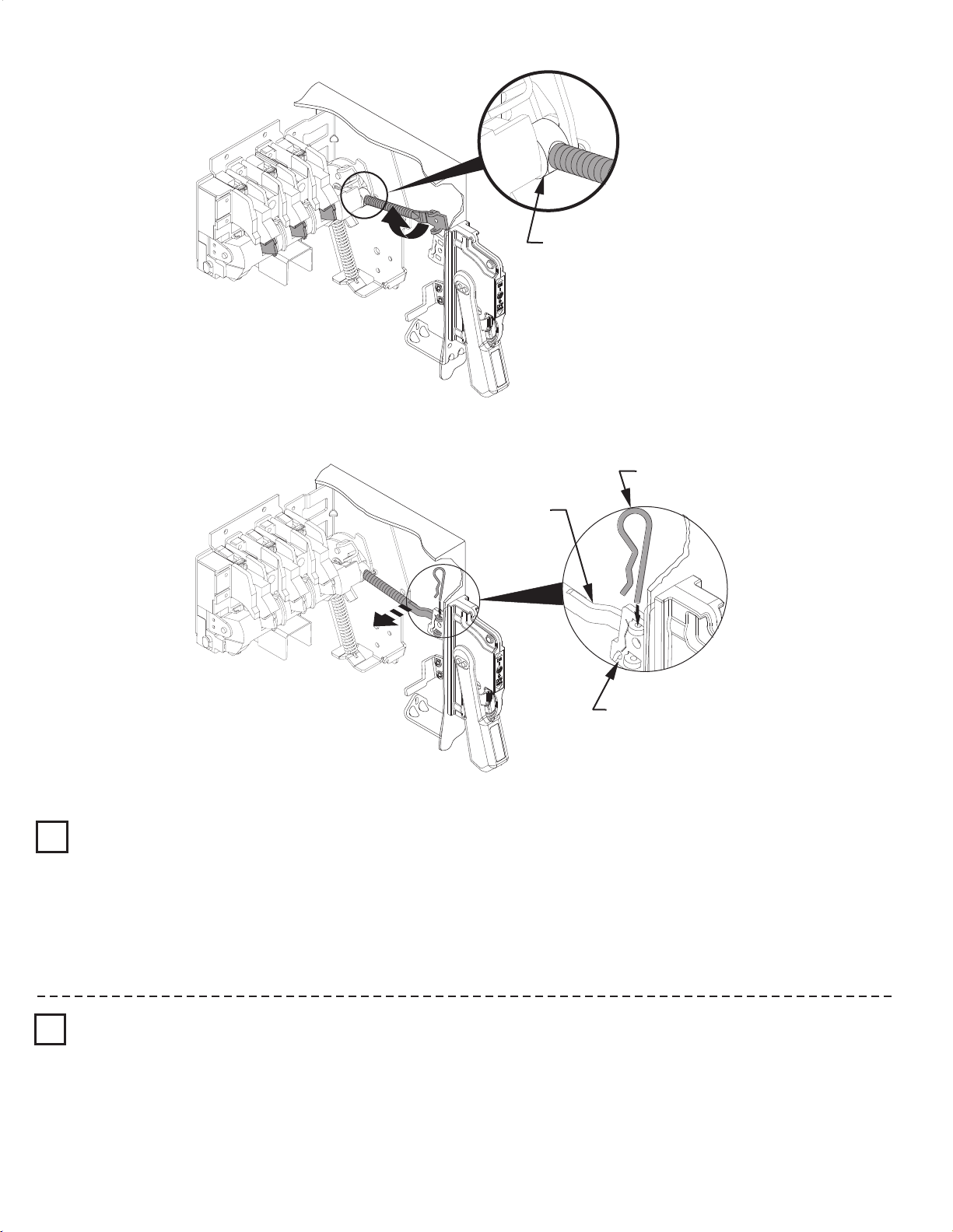
Primary Link
8a
Enclosure depth
8 in. or less
8b
Enclosure depth
greater than 8 in.
ATTENTION
CHECK FOR PROPER
OPERATION
(3)
Page 4
Connecting Rod Adjustment Procedure
Drive Bar
Hitch Pin
"ON" Position
1
Move disconnect handle to the "ON" position.
If switch does not fully close, return handle to "OFF" position.
Remove link spring hitch pin and disengage the connectiong rod from the primary link.
Turn connecting rod counter-clockwise (1 or more) full turns.
Re-engage connecting rod in primary link of handle, insert hitch pin and re-test
Repeat - as necessary.
Re-install link spring
Connecting
Rod
Primary Link
"OFF" Position
2
Move disconnect handle to the "OFF" position.
If switch does not fully open, return handle to "ON" position.
Remove hitch pin and link spring, then disengage the connectiong rod from the primary link.
Turn connecting rod clockwise (1 or more) full turns.
Re-engage connecting rod in primary link of handle, insert hitch pin and re-test.
Repeat - as necessary.
Re-install link spring
(4)
Page 5
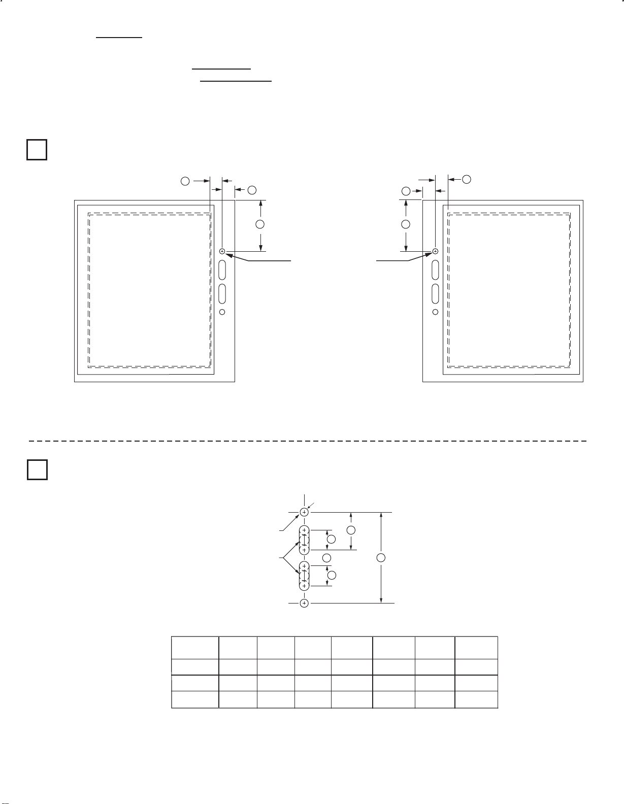
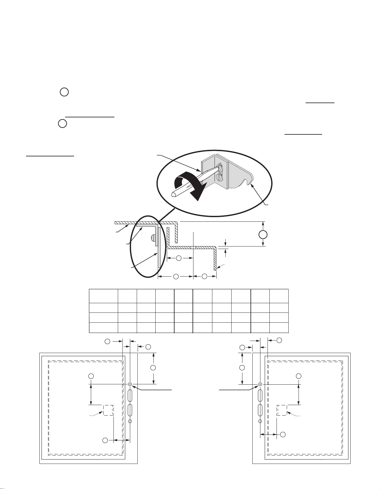
Enclosure without Handle Cutout
● Enclosures with a Flange Thickness less than 3/16" use dimensions below to install disconnect handle.
● Enclosures with a Flange Thickness 3/16" and greater use dimensions in alternate Mounting Kit 1494V-H3 to install disconnect
handle.
● Multi-Door Enclosures may require the need for a more rigid flange / mounting plate system, such as a Channel Support Kit. Use
dimensions in Channel Support Kit 1494V-H15, if handle is mounted on top of the channel.
Locate Handle
1
Drill Handle Holes
2
C
Right Hand Flange
C
B
A
B
A
Top Handle Hole
Left Hand Flange
Top Handle Hole
To make slot drill (3) 1/2" diameter holes and remove burrs
NEMA
SIZE
30A, 60A
100A
200A
A
(min)
4 - 5/8"
6 - 1/16"
10 - 1/8"
(min)
1 - 1/8"
1 - 1/8"
1 - 1/8"
(2) .265 Dia. Holes
G
H
J
H
Enclosure Dimensions
B
C
(max)
1 - 1/16"
1 - 1/16"
1 - 1/16"
F
4 - 11/16"
4 - 11/16"
4 - 11/16"
(5)
F
G
1 - 9/16"
1 - 9/16"
1 - 9/16"
H
1"
1"
1"
J
7/8"
7/8"
7/8"
Page 6
Door Catch Bracket Installation
Right hand installation shown (for left hand installation follow similar procedures)
Door Catch Mounting Bracket:
● Provided with projections for welding.
● Projections can also be used as a guide for drilling holes.
● Can be used as a template to drill corresponding holes in the enclosure door.
● User to supply the hardware for fastening the bracket.
● The bracket hardware must be inaccessible to unauthorized personnel.
● Fasteners must provide the degree of ingress protection for the environmental rating of the enclosure.
Dimension K (3/4" to 1")
● When using small disconnect handle kit only (1494F-P1, -M1 or -S1), use door catch provided with handle kit.
● When using small disconnect handle kit and small door hardware kits (1494V-L1, -LL1, -L2 or -LL2), use door catch
provided with door hardware kit.
Dimension K (1-1/8" to 1-3/8")
● When using small disconnect handle kit only (1494F-P1, -M1 or -S1), use door catch (40492-080-02) which can be
ordered from factory.
● When using small disconnect handle kit and large door hardware kits (1494V-L3 or -LL3), use door catch provided with
door hardware kit.
Door Catch
Mounting Bracket
Top
Enclosure Door
Door Catch
Mounting Bracket
Door Catch
NEMA
SIZE
30A, 60A
100A
200A
C
E
TOP VIEW
A
(min)
4 - 5/8"
6 - 1/16"
10 - 1/8"
B
(min)
1 - 1/8"
1 - 1/8"
1 - 1/8"
B
C
D
B
Enclosure Dimensions
C
A
(max)
1 - 1/16"
1 - 1/16"
1 - 1/16"
D
1 - 5/8"
1 - 5/8"
1 - 5/8"
E
2 - 3/8"
2 - 3/8"
2 - 3/8"
Flange
Thickness
Enclosure
Base
F
4 - 11/16"
4 - 11/16"
4 - 11/16"
G
1 - 9/16"
1 - 9/16"
1 - 9/16"
B
A
Door Catch
K
H
1"
1"
1"
J
7/8"
7/8"
7/8"
C
E
Top Handle Hole
Door Catch
Mounting
Bracket
D
D
Door Catch
Mounting
Bracket
Right Hand Flange Left Hand Flange
(6)
Page 7
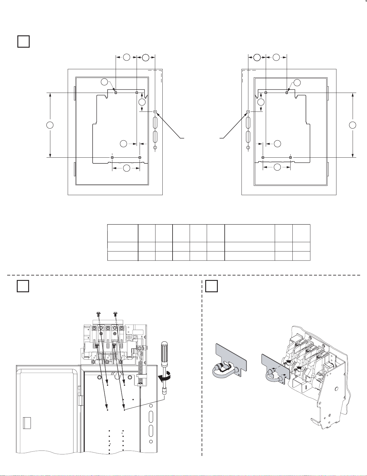
Disconnect Switch Installation
Locate Disconnect Switch
1
FF
CC
HH HH
GG
AAAAAAAA
AA
BB BB
Top Handle Hole
AAAAAAAAAAAAAAAAAAAAAAEE
CC
FF
GG
Right Hand Flange Left Hand Flange
Panel Mounting Dimensions
Switch
Size
AA BB CC DD
EE
(4 Mounting Plate Holes)
FF
HH
DDDD
30A, 60A, 100A
200A
3-1/16" 2-1/2" 2-1/4" 5-1/4"
3-9/16" 3-9/16" 2" 8-1/4" 3-9/16" 4-1/4" 1-1/8"7/32" Dia.
3-1/16"
11/64" Dia.
2-1/4"GG----
This dimension can be 2-1/4" if necessary, to avoid interference with panel mounting studs in some 8 inch deep enclosures.
Install Disconnect Switch Assemble and Install Line Terminal Guard
2 3
23 - 37 lb-in (30A - 100A)
40 - 60 lb-in (200A)
LINE TERMINAL GUARD
LINE TERMINAL GUARD
(7)
Page 8
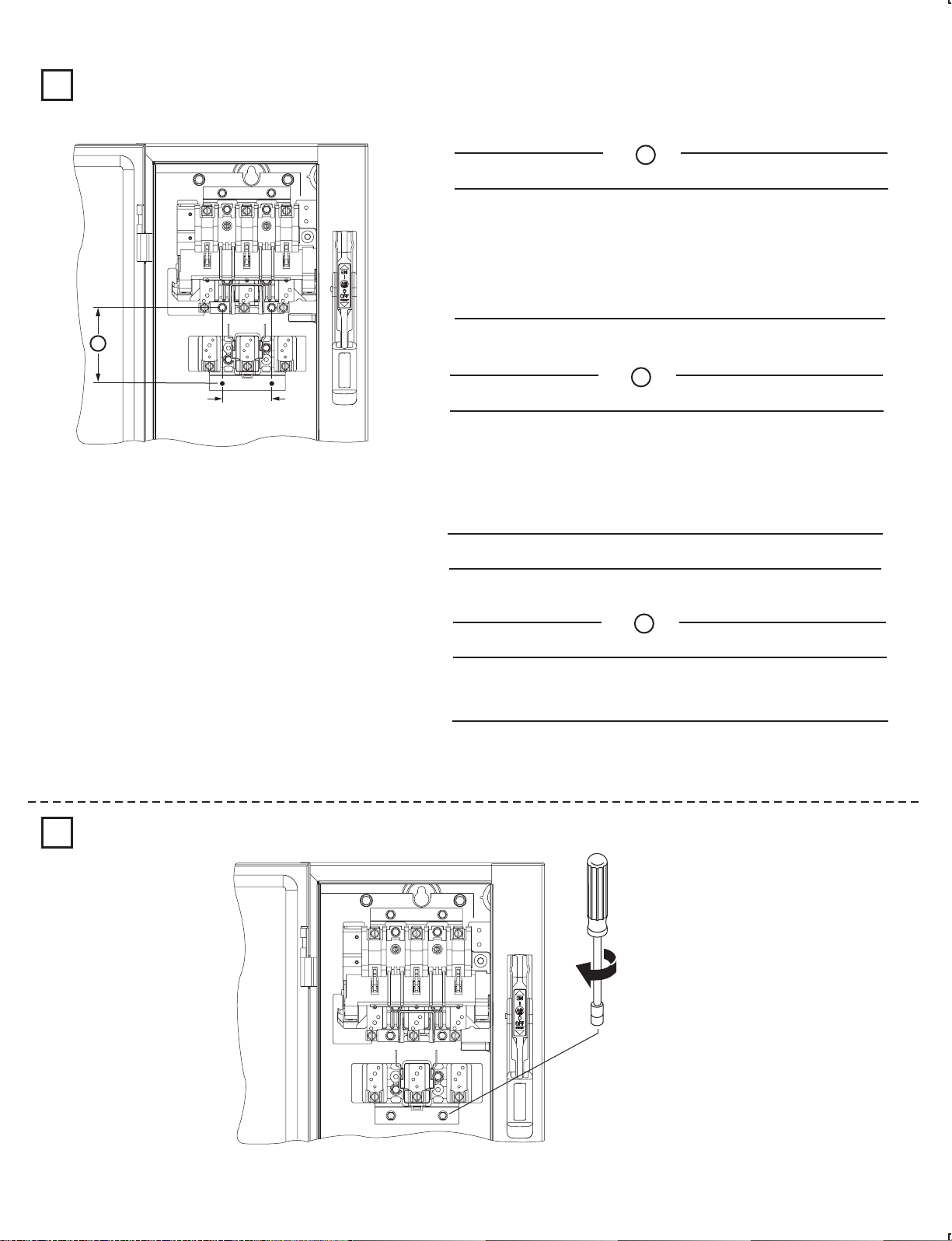
Trailer Fuse Block Installation (Switch Rating 30A - 100A)
Trailer Fuse Block Location
1
Note: Not required for non-fusible disconnect switch applications.
30 Amp Trailer Fuse Block (1494V-FS30)
Amps Voltage Class Fuse
30
30
30
30
60
60
60
60
250
600
600
600
250
600
600
600
H/R
H/R
J
HRCII-C
H/R
H/R
J
HRCII-C
A
2-27/32"
5-5/8"
2-27/32"
4-3/16"
3-5/8"
6-1/8"
3"
4-3/16"
Torque (lb-in)Fuse
Block
23
Fuse
Clip
-
37 22-37 20-25 20-25
Lug to
Terminal
Wire
into Lug
A
2-1/4"
Amps Voltage Class Fuse
30
30
30
30
60
60
60
60
100
100
Amps Voltage Class Fuse
60
60
60
60
100
100
100
100
200
60 Amp Trailer Fuse Block (1494V-FS60)
A
Block
250
600
600
600
250
600
600
600
600
600
250
600
600
600
250
600
600
600
600
H/R
H/R
HRCII-C
H/R
H/R
HRCII-C
H/R
100 Amp Trailer Fuse Block (1494V-FS100)
H/R
H/R
HRCII-C
H/R
H/R
HRCII-C
2-27/32"
5-5/8"
2-27/32"
J
4-3/16"
3-5/8"
6-1/8"
J
J
J
J
J
3"
4-3/16"
4-15/16"
8-1/8"
A
4-3/16"
3-9/16"
6-11/16"
4-11/16"
6-11/16"
8-11/16"
5-1/2"
7-9/16"
6-1/4"
-
37
23
23
-
37 16-22 40-60 45-50
Block
23
-
37
23
-
37 16-22 90-110 150-165
Torque (lb-in)Fuse
Fuse
23-37 40-60 45-50
Lug to
Clip
Terminal
Torque (lb-in)Fuse
Fuse
22-37 90-110 150-165
Clip
Lug to
Terminal
Wire
into Lug
Wire
into Lug
Install Trailer Fuse Block
2
23 - 37 lb-in
(8)
Page 9
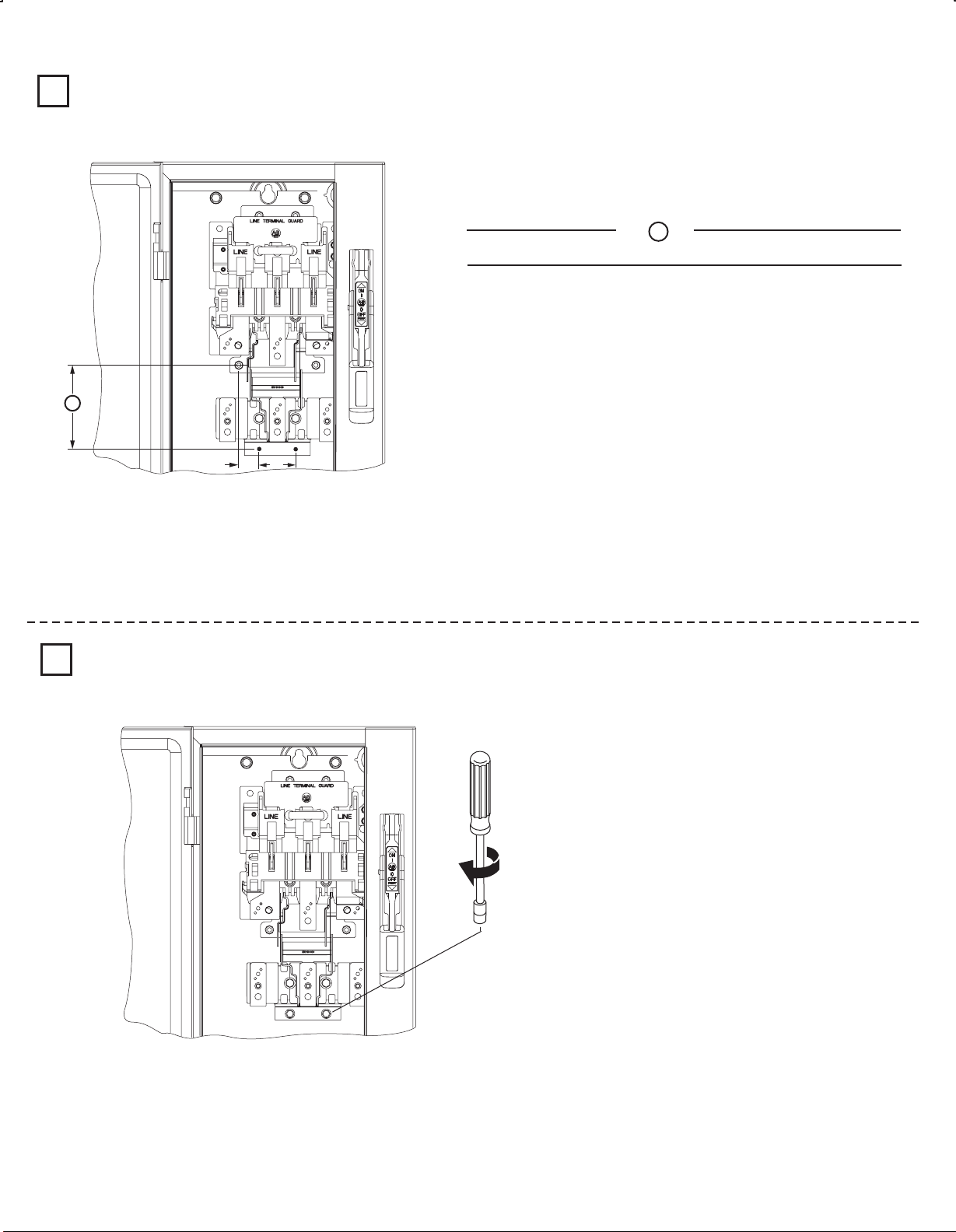
Trailer Fuse Block Installation (Switch Rating 200A)
Trailer Fuse Block Location
1
Note: Not required for non-fusible disconnect switch applications.
Amps Voltage Class Fuse
100
100
100
100
200
200
200
200
B
400
250
600
600
600
250
600
600
600
600
200 Amp Trailer Fuse Block (1494V-FS200)
60
Fuse
Clip
16
16
Torque (lb-in)Fuse
-
22
-
22
Lug to
Terminal
175
H/R
H/R
J
HRCII-C
H/R
H/R
J
HRCII-C
J
B
5-7/8"
7-7/8"
4-5/8"
4-5/8"
6-3/4"
9-1/4"
5-3/8"
5-3/8"
6-1/4"
Block
40
-
Wire
into Lug
-
200 275-305
1 - 1/8"
Install Trailer Fuse Block
2
2"
40 - 60 lb-in
(9)
Page 10
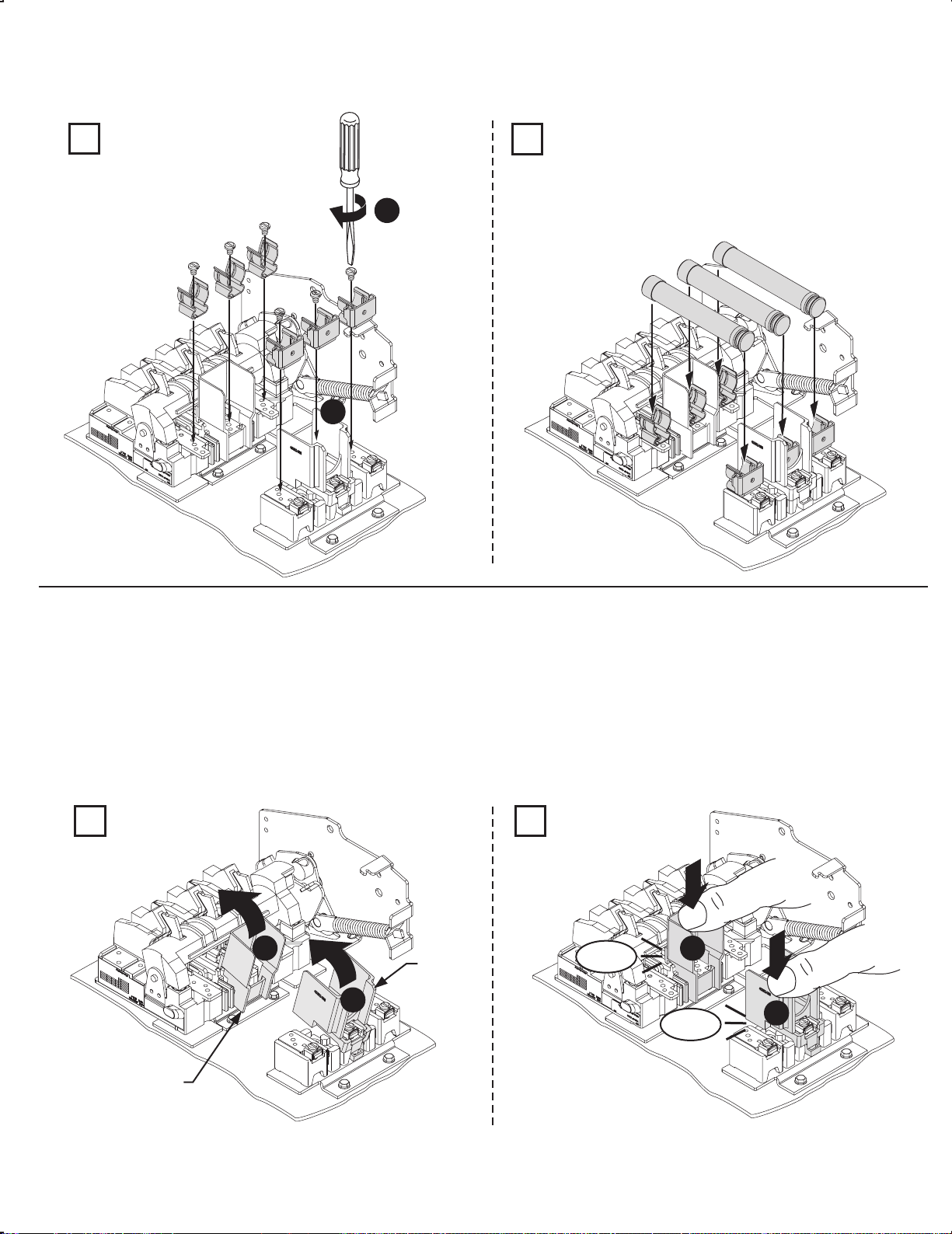
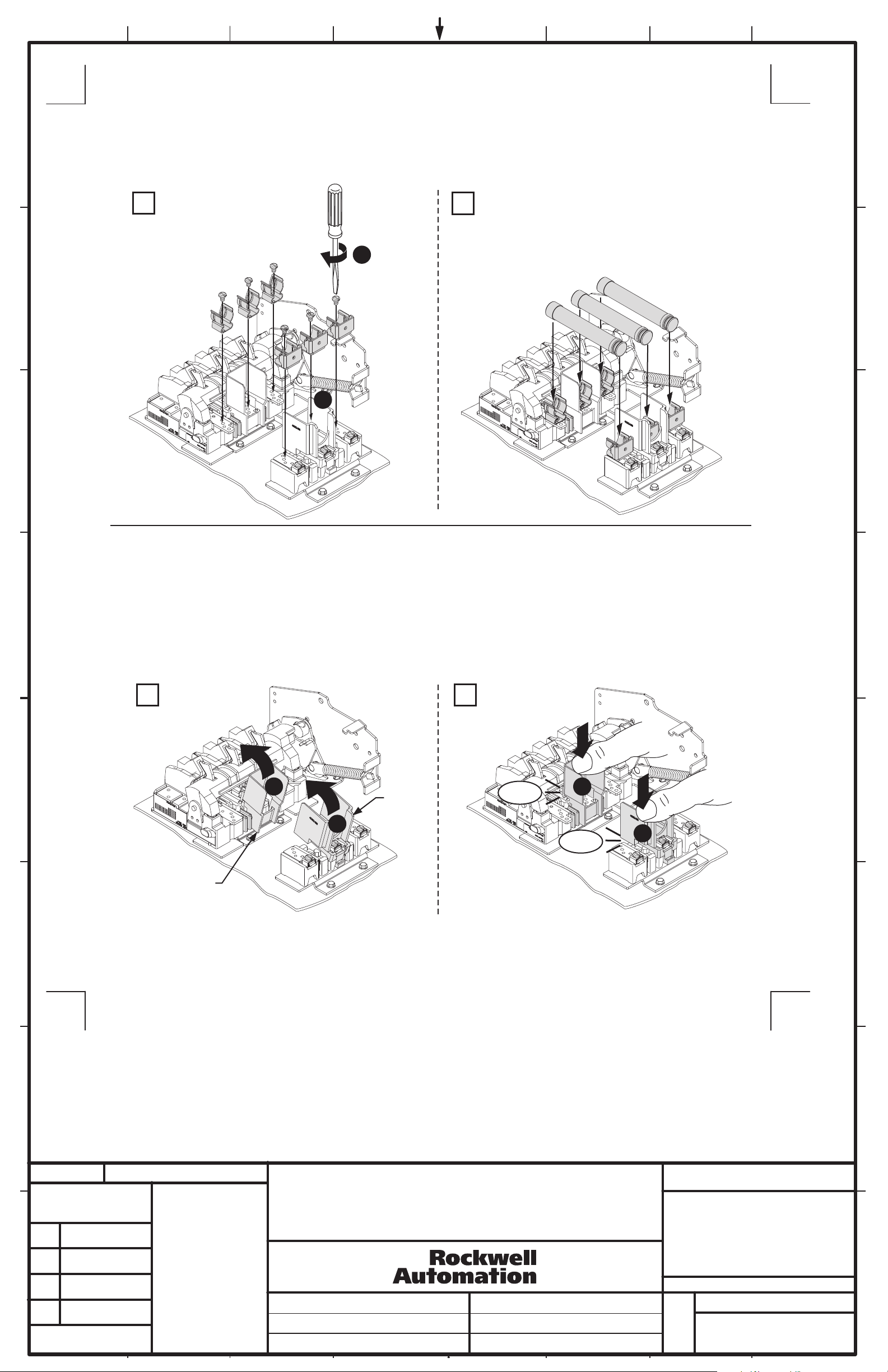
Switch Rating (30A, 60A Rating)
Fuse Clip Installation
1
2
23 - 37 lb-in
2
1
Phase Barrier Replacement Kit
1494F-PH2
NOTE: Fuse clips and lugs must be removed to add or replace phase barriers.
1 2
1
40392-098
2
CLICK
1
CLICK
2
40392-097
(10)
Page 11

Fuse Clip Installation (Switch Rating 100 Amp)
1
Phase Barrier Replacement Kit
1494F-PH3
Switch Phase Barrier
16 - 22 lb-in
1
2
2
2
1
Trailer Block Phase Barrier
23 - 37 lb-in
1
2
Fuse Clip Size and Class
60 A
100 A
200 A
200 A
600V H - R
600V H - R
600V H - R
250V H - R
2
2
1
1
Fuse Clip Size and Class
60 A
60 A
100 A
100 A
250V H - R
600V J
250V H - R
600V J
600V J200 A
3
1
CLICK
1
2
2
CLICK
(11)
Page 12

Fuse Clip Installation (Switch Rating 200A)
Switch for Right Hand Mechanism
1
16 - 22 lb-in
2
1
Switch for Left Hand Mechanism
1
16 - 22 lb-in
2
1
Switch for Right Hand Mechanism
2
1
23 - 37 lb-in
2
Switch for Left Hand Mechanism
2
23 - 37 lb-in
1
2
(12)
Page 13

Fuse Clip Installation (Switch Rating 200A) for 400A Class J Fuses (Cat. No. 1401-N171)
NOTICE
Switch with Right Hand Mechanism
1 1
Use of 400A fuses will void the UL listing of this product.
16 - 22 lb-in
2
1
Switch with Left Hand Mechanism
16 - 22 lb-in
2
1
Switch with Right Hand Mechanism
2 2
150 - 200 lb-in
Switch with Left Hand Mechanism
(13)
150 - 200 lb-in
Page 14

Phase Barrier Replacement Kit (Switch Rating 200A)
1494F-PH4
1
1
2
4
40 - 60 lb-in
2
CLICK
3
1
2
3
CLICK
(14)
Page 15

Bulletin 1494V Disconnect Switch Kit
Disconnect Kit
Switch
Handle
Connecting
Cat No.
Switch with Right Hand Mechanism
1494V-DS30 (30A)
1494V-DS60 (60A)
1494V-DS100 (100A)
1494V-DS200 (200A)
Switch with Left Hand Mechanism
1494V-DSX30 (30A)
1494V-DSX60 (60A)
1494V-DSX100 (100A)
1494V-DSX200 (200A)
1494F-M1 (5-1/2" Painted Metal) (30A - 200A)
1494F-P1 (5-1/2" Molded) (30A - 200A)
1494F-S1 (5-1/2" Stainless Steel) (30A - 200A)
1494V-RA3 (Standard) (30A - 100A)
Enclosure Working Depth: 6-3/4" to 9-1/8"
1494V-RA3 (Standard) (200A)
Enclosure Working Depth: 8-1/2" to 10-1/4"
Rod
1494V-RA4 (Extended)(30A - 100A)
Enclosure Working Depth: 6-3/4" to 21-5/8"
1494V-RA4 (Extended) (200A)
Enclosure Working Depth: 8-1/2" to 23-3/4"
Fuse
Block
Fuse
Clips
1494V-FS30 (30A)
1494V-FS60 (60A)
1494V-FS100 (100A)
1494V-FS200 (200A)
1401-N41 (Class H, 30A - 250V)
1401-N42 (Class H,J, 30A - 600V,
Class H, 60A-250V)
1401-N43 (Class H,J, 60A - 600V)
1401-N44 (Class H,J, 100A-250V, 100A-600V)
1401-N45 (Class H,J, 200A-250V, 200A-600V)
1401-N50 (Class R, 30A - 250V)
1401-N51 (Class R, 30A - 600V, 60A-250V)
1401-N52 (Class R, 60A - 600V)
1401-N53 (Class R, 100A - 250V, 100A-600V)
1401-N54 (Class R, 200A-250V, 200A-600V)
1401-N171 (Class J, 400A-250V / 600V)
(15)
Page 16

Bulletin 1494V Disconnect Switch Optional Accessory List
Optional Accessories
(Installation Instructions
Included with Accessory Kits)
Electrical
Interlock
Channel
Support Kit
Switch with Right Hand Mechanism
1495-N34 (1-N.O./N.C.) (30A - 100A)
1495-N35 (2-N.O./N.C.) (30A - 100A)
1495-N43 (1-N.O./N.C.) (200A)
1495-N44 (2-N.O./N.C.) (200A)
Switch with Left Hand Mechanism
1495-N37 (1-N.O./N.C.) (30A - 100A)
1495-N38 (2-N.O./N.C.) (30A - 100A)
1495-N39 (1-N.O./N.C.) (200A)
1495-N40 (2-N.O./N.C.) (200A)
1494V-H15 (30A - 200A)
Cat No.
42052-116-01 (7)
Printed in U.S.A.
Auxiliary
Contact
Auxiliary
Contact
Adapter Kit
Lug
Connectors
Phase
Barrier
Fuse
Cover
with Door
1495-N8 (1-N.O.) (30A - 200A)
1495-N9 (1-N.C.) (30A - 200A)
1495-N24 (30A - 100A)
(Required only for Switch with Left Hand
Mechanism)
1495-N25 (200A - 400A)
(Required only for Switch with Left Hand
Mechanism)
(Included)
(CU Wire Size #14 . . #8 AWG) (30A)
1494R-N1
(CU Wire Size #14 . . #4 AWG) (60A)
1494R-N2
(CU Wire Size #8 . . #1/0 AWG) (100A)
1494R-N3
(CU Wire Size #6 . . #4/0 AWG) (200A)
1494F-PH2 (30A / 60A)
1494F-PH3 (100A)
1494F-PH4 (200A)
Switch
Rating
30A
30A
60A
30A
60A
60A
100A
30A
60A
100A
200A
Switch with right hand mechanism
Switch with left hand mechanism
Fuse
Class
Non-Fusible
H, R
H, R
J
J
Non-Fusible
Non-Fusible
H, R
H, R
J
Fuse Clip
Rating
250V 600V
----
----
30A
----
60A
----
30A
30A
60A
60A
----
----
----
----
----
30A
----
60A
100A
100A
100A 100AH, R100A
200A 200AH, J, R200A
200A 200AH, J, R
Cat No.
1495-N64
1495-N65
1495-N66
1495-N67
1495-N62
Page 17

17"
8.50"
8.50"
FRONT SIDE
PAGE 2
FRONT SIDE
PAGE 15
BACK SIDE
PAGE 1
BACK SIDE
PAGE 16
FRONT SIDE
PAGE 4
FRONT SIDE
PAGE 13
BACK SIDE
PAGE 3
BACK SIDE
PAGE 14
FRONT SIDE
PAGE 6
FRONT SIDE
PAGE 11
BACK SIDE
PAGE 5
BACK SIDE
PAGE 12
FRONT SIDE
PAGE 8
FRONT SIDE
PAGE 9
BACK SIDE
PAGE 7
BACK SIDE
PAGE 10
17 17
BULLETIN 1494V VARIABLE DEPTH DISCONNECT SWITCH
INSTALLATION INSTRUCTION SHEET
5 1020139
6
7 1032142
42052-116
OF
N/A
N/A
N/A
REVISION
AUTHORIZATION
DR.
CHKD.
APPD.
DATE
DATE
DATE
E - DOC
LOCATION: MILWAUKEE, WISCONSIN U.S.A.
DWG.
SIZE
SHEET
B
1 2 3 4 5 6 7 8
REFERENCE
DIMENSIONS APPLY BEFORE
SURFACE TREATMENT
(DIMENSIONS IN INCHES)
TOLERANCES UNLESS
OTHERWISE SPECIFIED
.XX:
.XXX:
ANGLES:
42052
------------- -------------
-------------
-------------
-------------
-------------
THIS DRAWING IS THE PROPERTY OF
ROCKWELL AUTOMATION, INC.
OR ITS SUBSIDIARIES AND MAY NOT BE COPIED,
USED OR DISCLOSED FOR ANY PURPOSE
EXCEPT AS AUTHORIZED IN WRITING BY
ROCKWELL AUTOMATION, INC.
PART
NO.
MATERIAL
CHG.
CHAR. SIZE
FLAT FOLD
-01 7
TWO SIDES PRINTED
17" W x 11" H 8-1/2" W x 11" H
BODY STOCK WHITE
BODY INK BLACK
STAPLED
1021282
Page 18

A
HOLD FLUSH
TO INSIDE
OF ENCLOSURE
MEASURE TO
INSIDE OF THE
TOP OF ENCLOSURE
TOP HANDLE HOLE
BOTTOM HANDLE HOLE
Disconnect Handle Installation
Disconnect Switch Installation (Right hand installation shown. For left hand installation follow similar procedure.)
1
2
Install gasket.
30-40 lb-in
Install handle and spring bracket.
Use template A to locate handle holes on mounting plate.
Overlay template B (30 A - 100 A) over A .
Overlay template C (200 A) over A .
7-11 lb-in
Install defeater lever.
Cutting Connecting Rod
N
Enclosure
Working Depth
(Inside Flange
of Enclosure to
Mounting Plate)
Mounting
Plate
Measure working depth of enclosure.
3
Measure, mark and
cut connecting rod.
N minus 3-1/8"
(30A - 100A)
N minus 3-1/4"
(200A)
23 - 37 lb-in
(30A - 100A)
40 - 60 lb-in
(200A)
TAPE
HOLD FLUSH
TO INSIDE
OF ENCLOSURE
MEASURE TO
INSIDE OF THE
TOP OF ENCLOSURE
TOP
BOTT
2
4
A
11
5
1
1
2
Remove burrs
3
2 3
Install disconnect switch.
7
6
1
3
A
HOLD FLUSH
TO INSIDE
OF ENCLOSURE
MEASURE TO
INSIDE OF THE
TOP OF ENCLOSURE
TOP
BOTT
B
or
C
2 - 1/4"
5 - 1/4"
2 - 1/4"
4 - 11/16"
3 - 1/16"
Switch Mounting Holes
Center punch and drill (4) 11/64" holes for
tap-tite screws provided with
switch
Center punch and
drill (4) holes
for thread forming
(TAP-TITE) screws
provided with switch.
11/64" Dia. (30A - 100A)
7/32" Dia (200A)
BULLETIN 1494V VARIABLE DEPTH DISCONNECT SWITCH
INSTALLATION INSTRUCTION SHEET
5 1020139
42052-116
OF
N/A
N/A
N/A
REVISION
AUTHORIZATION
DR.
CHKD.
APPD.
DATE
DATE
DATE
E - DOC
LOCATION: MILWAUKEE, WISCONSIN U.S.A.
DWG.
SIZE
SHEET
B
1 2 3 4 5 6 7 8
REFERENCE
DIMENSIONS APPLY BEFORE
SURFACE TREATMENT
(DIMENSIONS IN INCHES)
TOLERANCES UNLESS
OTHERWISE SPECIFIED
.XX:
.XXX:
ANGLES:
42052
- - - - - - - - - - - - - -
- - - - - - -
- - - - - - -
- - - - - - -
- - - - - - -
THIS DRAWING IS THE PROPERTY OF
ROCKWELL AUTOMATION, INC.
OR ITS SUBSIDIARIES AND MAY NOT BE COPIED,
USED OR DISCLOSED FOR ANY PURPOSE
EXCEPT AS AUTHORIZED IN WRITING BY
ROCKWELL AUTOMATION, INC.
2 17
6 1021282
7 1032142
QUICK INSTALLATION GUIDE
(2)
Page 19

Connecting Rod Installation
4
Verify that disconnect switch and handle are in "OFF"
position. (Switch blades will be visible)
Drive Bar
Pull up
(30A - 60A - 100A)
1
2
Rotate connecting rod into
drive bar (see table).
3
4
Enclosure depth
8 in. or less
Enclosure depth
greater than 8 in.
CHECK FOR PROPER
OPERATION
ATTENTION
7
8b
8a
Push rod down and
verify if rod is nearly
touching bottom of bolt
head. (If not, rotate rod
up to 5 full turns in
either direction)
(200A)
Push down
Push rod down and verify if rod
is approximately 1/8" from
touching bottom of bolt head.
(If not, rotate rod up to 5 full
turns in either direction)
1/8" Gap
Switch Rating
30A - 60A - 100A
200A
Full Turns Engagement
10
13
BULLETIN 1494V VARIABLE DEPTH DISCONNECT SWITCH
INSTALLATION INSTRUCTION SHEET
5 1020139
42052-116
OF
N/A
N/A
N/A
REVISION
AUTHORIZATION
DR.
CHKD.
APPD.
DATE
DATE
DATE
E - DOC
LOCATION: MILWAUKEE, WISCONSIN U.S.A.
DWG.
SIZE
SHEET
B
1 2 3 4 5 6 7 8
REFERENCE
DIMENSIONS APPLY BEFORE
SURFACE TREATMENT
(DIMENSIONS IN INCHES)
TOLERANCES UNLESS
OTHERWISE SPECIFIED
.XX:
.XXX:
ANGLES:
42052
- - - - - - - - - - - - - -
- - - - - - -
- - - - - - -
- - - - - - -
- - - - - - -
THIS DRAWING IS THE PROPERTY OF
ROCKWELL AUTOMATION, INC.
OR ITS SUBSIDIARIES AND MAY NOT BE COPIED,
USED OR DISCLOSED FOR ANY PURPOSE
EXCEPT AS AUTHORIZED IN WRITING BY
ROCKWELL AUTOMATION, INC.
3 17
6 1021282
7 1032142
QUICK INSTALLATION GUIDE (CONTINUED)
(3)
Connecting
Rod
Hitch Pin
Primary Link
5
6
5
6
Page 20

(4)
Connecting Rod Adjustment Procedure
"ON" Position
Move disconnect handle to the "ON" position.
If switch does not fully close, return handle to "OFF" position.
Remove link spring hitch pin and disengage the connectiong rod from the primary link.
Turn connecting rod counter-clockwise (1 or more) full turns.
Re-engage connecting rod in primary link of handle, insert hitch pin and re-test
Repeat - as necessary.
Re-install link spring
"OFF" Position
Move disconnect handle to the "OFF" position.
If switch does not fully open, return handle to "ON" position.
Remove hitch pin and link spring, then disengage the connectiong rod from the primary link.
Turn connecting rod clockwise (1 or more) full turns.
Re-engage connecting rod in primary link of handle, insert hitch pin and re-test.
Repeat - as necessary.
Re-install link spring
1
2
Connecting
Rod
Hitch Pin
Primary Link
Drive Bar
BULLETIN 1494V VARIABLE DEPTH DISCONNECT SWITCH
INSTALLATION INSTRUCTION SHEET
5 1020139
42052-116
OF
N/A
N/A
N/A
REVISION
AUTHORIZATION
DR.
CHKD.
APPD.
DATE
DATE
DATE
E - DOC
LOCATION: MILWAUKEE, WISCONSIN U.S.A.
DWG.
SIZE
SHEET
B
1 2 3 4 5 6 7 8
REFERENCE
DIMENSIONS APPLY BEFORE
SURFACE TREATMENT
(DIMENSIONS IN INCHES)
TOLERANCES UNLESS
OTHERWISE SPECIFIED
.XX:
.XXX:
ANGLES:
42052
- - - - - - - - - - - - - -
- - - - - - -
- - - - - - -
- - - - - - -
- - - - - - -
THIS DRAWING IS THE PROPERTY OF
ROCKWELL AUTOMATION, INC.
OR ITS SUBSIDIARIES AND MAY NOT BE COPIED,
USED OR DISCLOSED FOR ANY PURPOSE
EXCEPT AS AUTHORIZED IN WRITING BY
ROCKWELL AUTOMATION, INC.
4 17
6 1021282
7 1032142
Page 21

BULLETIN 1494V VARIABLE DEPTH DISCONNECT SWITCH
INSTALLATION INSTRUCTION SHEET
5 1020139
7 1032142
42052-116
OF
N/A
N/A
N/A
REVISION
AUTHORIZATION
DR.
CHKD.
APPD.
DATE
DATE
DATE
E - DOC
LOCATION: MILWAUKEE, WISCONSIN U.S.A.
DWG.
SIZE
SHEET
B
1 2 3 4 5 6 7 8
REFERENCE
DIMENSIONS APPLY BEFORE
SURFACE TREATMENT
(DIMENSIONS IN INCHES)
TOLERANCES UNLESS
OTHERWISE SPECIFIED
.XX:
.XXX:
ANGLES:
42052
------------- -------------
-------------
-------------
-------------
-------------
THIS DRAWING IS THE PROPERTY OF
ROCKWELL AUTOMATION, INC.
OR ITS SUBSIDIARIES AND MAY NOT BE COPIED,
USED OR DISCLOSED FOR ANY PURPOSE
EXCEPT AS AUTHORIZED IN WRITING BY
ROCKWELL AUTOMATION, INC.
Enclosure without Handle Cutout
1
To make slot drill (3) 1/2" diameter holes and remove burrs
Top Handle Hole
Top Handle Hole
Locate Handle
Right Hand Flange
Enclosure Dimensions
Left Hand Flange
(2) .265 Dia. Holes
Drill Handle Holes
B
C
A
C
B
A
2
F
G
H
J
H
(5)
● Enclosures with a Flange Thickness less than 3/16" use dimensions below to install disconnect handle.
● Enclosures with a Flange Thickness 3/16" and greater use dimensions in alternate Mounting Kit 1494V-H3 to install disconnect
handle.
● Multi-Door Enclosures may require the need for a more rigid flange / mounting plate system, such as a Channel Support Kit. Use
dimensions in Channel Support Kit 1494V-H15, if handle is mounted on top of the channel.
F
4 - 11/16"
4 - 11/16"
4 - 11/16"
G
1 - 9/16"
1 - 9/16"
1 - 9/16"
H
1"
1"
1"
J
7/8"
7/8"
7/8"
1 - 1/16"
C
(max)
1 - 1/16"
1 - 1/16"
B
(min)
1 - 1/8"
1 - 1/8"
1 - 1/8"
A
(min)
4 - 5/8"
6 - 1/16"
10 - 1/8"
NEMA
SIZE
30A, 60A
200A
100A
6 1021282
5 17
- - - - - - -
Page 22

Door Catch Bracket Installation
Right hand installation shown (for left hand installation follow similar procedures)
Top Handle Hole
Door Catch
Mounting
Bracket
E
D
Door Catch
Mounting
Bracket
Right Hand Flange Left Hand Flange
D
B
C
A
C
B
A
E
(6)
C
B
Enclosure Door
Flange
Thickness
K
D
Enclosure
Base
TOP VIEW
Door Catch Mounting Bracket:
● Provided with projections for welding.
● Projections can also be used as a guide for drilling holes.
● Can be used as a template to drill corresponding holes in the enclosure door.
● User to supply the hardware for fastening the bracket.
● The bracket hardware must be inaccessible to unauthorized personnel.
● Fasteners must provide the degree of ingress protection for the environmental rating of the enclosure.
Dimension K (3/4" to 1")
● When using small disconnect handle kit only (1494F-P1, -M1 or -S1), use door catch provided with handle kit.
● When using small disconnect handle kit and small door hardware kits (1494V-L1, -LL1, -L2 or -LL2), use door catch
provided with door hardware kit.
Dimension K (1-1/8" to 1-3/8")
● When using small disconnect handle kit only (1494F-P1, -M1 or -S1), use door catch (40492-080-02) which can be
ordered from factory.
● When using small disconnect handle kit and large door hardware kits (1494V-L3 or -LL3), use door catch provided with
door hardware kit.
Enclosure Dimensions
1 - 5/8"
D
1 - 5/8"
1 - 5/8"
E
2 - 3/8"
2 - 3/8"
2 - 3/8"
F
4 - 11/16"
4 - 11/16"
4 - 11/16"
G
1 - 9/16"
1 - 9/16"
1 - 9/16"
H
1"
1"
1"
J
7/8"
7/8"
7/8"
1 - 1/16"
C
(max)
1 - 1/16"
1 - 1/16"
B
(min)
1 - 1/8"
1 - 1/8"
1 - 1/8"
A
(min)
4 - 5/8"
6 - 1/16"
10 - 1/8"
NEMA
SIZE
30A, 60A
200A
100A
6 17
BULLETIN 1494V VARIABLE DEPTH DISCONNECT SWITCH
INSTALLATION INSTRUCTION SHEET
5 1020139
7 1032142
42052-116
OF
N/A
N/A
N/A
REVISION
AUTHORIZATION
DR.
CHKD.
APPD.
DATE
DATE
DATE
E - DOC
LOCATION: MILWAUKEE, WISCONSIN U.S.A.
DWG.
SIZE
SHEET
B
1 2 3 4 5 6 7 8
REFERENCE
DIMENSIONS APPLY BEFORE
SURFACE TREATMENT
(DIMENSIONS IN INCHES)
TOLERANCES UNLESS
OTHERWISE SPECIFIED
.XX:
.XXX:
ANGLES:
42052
------------- -------------
-------------
-------------
-------------
-------------
THIS DRAWING IS THE PROPERTY OF
ROCKWELL AUTOMATION, INC.
OR ITS SUBSIDIARIES AND MAY NOT BE COPIED,
USED OR DISCLOSED FOR ANY PURPOSE
EXCEPT AS AUTHORIZED IN WRITING BY
ROCKWELL AUTOMATION, INC.
6 1021282
Door Catch
Mounting Bracket
Door Catch
Mounting Bracket
Door Catch
Door Catch
Top
Page 23

Disconnect Switch Installation
3-1/16" � 2-1/2" 2-1/4" 5-1/4"
AA BB CC DD
3-1/16"
EE
2-1/4"GG----
HH
11/64" Dia.
FF
(4 Mounting Plate Holes)
Locate Disconnect Switch
Right Hand Flange Left Hand Flange
(7)
Switch
Size
30A, 60A, 100A
� This dimension can be 2-1/4" if necessary, to avoid interference with panel mounting studs in some 8 inch deep enclosures.
3-9/16" 3-9/16" 2" 8-1/4" 3-9/16" 4-1/4" 1-1/8"7/32" Dia.
200A
BB BB
DDDD
AAAAAAAAAAAAAAAAAAAAAAEE
AAAAAAAA
CC
GG
HH HH
CC
FF
FF
AA
GG
Panel Mounting Dimensions
1
Install Disconnect Switch Assemble and Install Line Terminal Guard
23 - 37 lb-in (30A - 100A)
40 - 60 lb-in (200A)
LINE TERMINAL GUARD
LINE TERMINAL GUARD
2 3
BULLETIN 1494V VARIABLE DEPTH DISCONNECT SWITCH
INSTALLATION INSTRUCTION SHEET
5 1020139
6
7 1032142
1011282
42052-116
OF
N/A
N/A
N/A
REVISION
AUTHORIZATION
DR.
CHKD.
APPD.
DATE
DATE
DATE
E - DOC
LOCATION: MILWAUKEE, WISCONSIN U.S.A.
DWG.
SIZE
SHEET
B
1 2 3 4 5 6 7 8
REFERENCE
DIMENSIONS APPLY BEFORE
SURFACE TREATMENT
(DIMENSIONS IN INCHES)
TOLERANCES UNLESS
OTHERWISE SPECIFIED
.XX:
.XXX:
ANGLES:
42052
------------- -------------
-------------
-------------
-------------
-------------
THIS DRAWING IS THE PROPERTY OF
ROCKWELL AUTOMATION, INC.
OR ITS SUBSIDIARIES AND MAY NOT BE COPIED,
USED OR DISCLOSED FOR ANY PURPOSE
EXCEPT AS AUTHORIZED IN WRITING BY
ROCKWELL AUTOMATION, INC.
7 17
Top Handle Hole
Page 24
(8)
Trailer Fuse Block Installation (Switch Rating 30A - 100A)
Note: Not required for non-fusible disconnect switch applications.
1
2
23 - 37 lb-in
Trailer Fuse Block Location
Install Trailer Fuse Block
30 Amp Trailer Fuse Block (1494V-FS30)
Torque (lb-in)Fuse
23
-
37
2-27/32"
5-5/8"
2-27/32"
4-3/16"
3-5/8"
6-1/8"
3"
4-3/16"
30
30
30
30
60
60
60
60
250
600
600
600
250
600
600
600
H/R
H/R
J
HRCII-C
H/R
H/R
J
HRCII-C
22-37 90-110 150-165
23
-
37 22-37 20-25 20-25
23
-
37 16-22 90-110 150-165
Amps Voltage Class Fuse
Block
A
Fuse
Clip
Lug to
Terminal
Wire
into Lug
60 Amp Trailer Fuse Block (1494V-FS60)
Torque (lb-in)Fuse
23
-
37
2-27/32"
5-5/8"
2-27/32"
4-3/16"
3-5/8"
6-1/8"
3"
4-3/16"
4-15/16"
8-1/8"
30
30
30
30
60
60
60
60
100
100
250
600
600
600
250
600
600
600
600
600
H/R
H/R
J
HRCII-C
H/R
H/R
J
HRCII-C
J
H/R
23-37 40-60 45-50
23
-
37 16-22 40-60 45-50
Amps Voltage Class Fuse
Block
A
Fuse
Clip
Lug to
Terminal
Wire
into Lug
100 Amp Trailer Fuse Block (1494V-FS100)
Torque (lb-in)Fuse
4-3/16"
3-9/16"
6-11/16"
4-11/16"
6-11/16"
8-11/16"
5-1/2"
7-9/16"
6-1/4"
60
60
60
60
100
100
100
100
200
250
600
600
600
250
600
600
600
600
H/R
J
H/R
HRCII-C
H/R
H/R
J
HRCII-C
J
Amps Voltage Class Fuse
Block
A
Fuse
Clip
Lug to
Terminal
Wire
into Lug
A
2-1/4"
BULLETIN 1494V VARIABLE DEPTH DISCONNECT SWITCH
INSTALLATION INSTRUCTION SHEET
5 1020139
6 1021282
7 1032142
42052-116
OF
N/A
N/A
N/A
REVISION
AUTHORIZATION
DR.
CHKD.
APPD.
DATE
DATE
DATE
E - DOC
LOCATION: MILWAUKEE, WISCONSIN U.S.A.
DWG.
SIZE
SHEET
B
1 2 3 4 5 6 7 8
REFERENCE
DIMENSIONS APPLY BEFORE
SURFACE TREATMENT
(DIMENSIONS IN INCHES)
TOLERANCES UNLESS
OTHERWISE SPECIFIED
.XX:
.XXX:
ANGLES:
42052
------------- -------------
-------------
-------------
-------------
-------------
THIS DRAWING IS THE PROPERTY OF
ROCKWELL AUTOMATION, INC.
OR ITS SUBSIDIARIES AND MAY NOT BE COPIED,
USED OR DISCLOSED FOR ANY PURPOSE
EXCEPT AS AUTHORIZED IN WRITING BY
ROCKWELL AUTOMATION, INC.
8 17
Page 25

(9)
2
Install Trailer Fuse Block
1 - 1/8"
Trailer Fuse Block Installation (Switch Rating 200A)
Note: Not required for non-fusible disconnect switch applications.
1
40 - 60 lb-in
Trailer Fuse Block Location
200 Amp Trailer Fuse Block (1494V-FS200)
Torque (lb-in)Fuse
40
-
60
5-7/8"
7-7/8"
4-5/8"
4-5/8"
6-3/4"
9-1/4"
5-3/8"
5-3/8"
6-1/4"
100
100
100
100
200
200
200
200
400
250
600
600
600
250
600
600
600
600
H/R
H/R
J
HRCII-C
H/R
H/R
J
HRCII-C
J
16
-
22
16
-
22
175
-
200 275-305
Amps Voltage Class Fuse
Block
B
Fuse
Clip
Lug to
Terminal
Wire
into Lug
B
2"
9 17
BULLETIN 1494V VARIABLE DEPTH DISCONNECT SWITCH
INSTALLATION INSTRUCTION SHEET
5 1020139
7 1032142
42052-116
OF
N/A
N/A
N/A
REVISION
AUTHORIZATION
DR.
CHKD.
APPD.
DATE
DATE
DATE
E - DOC
LOCATION: MILWAUKEE, WISCONSIN U.S.A.
DWG.
SIZE
SHEET
B
1 2 3 4 5 6 7 8
REFERENCE
DIMENSIONS APPLY BEFORE
SURFACE TREATMENT
(DIMENSIONS IN INCHES)
TOLERANCES UNLESS
OTHERWISE SPECIFIED
.XX:
.XXX:
ANGLES:
42052
------------- -------------
-------------
-------------
-------------
-------------
THIS DRAWING IS THE PROPERTY OF
ROCKWELL AUTOMATION, INC.
OR ITS SUBSIDIARIES AND MAY NOT BE COPIED,
USED OR DISCLOSED FOR ANY PURPOSE
EXCEPT AS AUTHORIZED IN WRITING BY
ROCKWELL AUTOMATION, INC.
6 1021282
Page 26
Switch Rating (30A, 60A Rating)
Fuse Clip Installation
Phase Barrier Replacement Kit
1494F-PH2
NOTE: Fuse clips and lugs must be removed to add or replace phase barriers.
1 2
2
1
23 - 37 lb-in
(10)
1
1
2
2
1
2
40392-098
40392-097
CLICK
CLICK
10 17
BULLETIN 1494V VARIABLE DEPTH DISCONNECT SWITCH
INSTALLATION INSTRUCTION SHEET
5 1020139
7 1032142
42052-116
OF
N/A
N/A
N/A
REVISION
AUTHORIZATION
DR.
CHKD.
APPD.
DATE
DATE
DATE
E - DOC
LOCATION: MILWAUKEE, WISCONSIN U.S.A.
DWG.
SIZE
SHEET
B
1 2 3 4 5 6 7 8
REFERENCE
DIMENSIONS APPLY BEFORE
SURFACE TREATMENT
(DIMENSIONS IN INCHES)
TOLERANCES UNLESS
OTHERWISE SPECIFIED
.XX:
.XXX:
ANGLES:
42052
------------- -------------
-------------
-------------
-------------
-------------
THIS DRAWING IS THE PROPERTY OF
ROCKWELL AUTOMATION, INC.
OR ITS SUBSIDIARIES AND MAY NOT BE COPIED,
USED OR DISCLOSED FOR ANY PURPOSE
EXCEPT AS AUTHORIZED IN WRITING BY
ROCKWELL AUTOMATION, INC.
6 1021282
Page 27

2
1
3
Phase Barrier Replacement Kit
1494F-PH3
Switch Phase Barrier
Fuse Clip Installation (Switch Rating 100 Amp)
1
2
16 - 22 lb-in
600V H - R
Fuse Clip Size and Class
600V H - R
600V H - R
250V H - R
60 A
100 A
200 A
200 A
250V H - R
Fuse Clip Size and Class
600V J
250V H - R
600V J
60 A
60 A
100 A
100 A
600V J200 A
23 - 37 lb-in
(11)
2
1
1
1
1
2
1
2
1
2
2
Trailer Block Phase Barrier
2
CLICK
CLICK
BULLETIN 1494V VARIABLE DEPTH DISCONNECT SWITCH
INSTALLATION INSTRUCTION SHEET
5 1020139
6
7 1032142
42052-116
OF
N/A
N/A
N/A
REVISION
AUTHORIZATION
DR.
CHKD.
APPD.
DATE
DATE
DATE
E - DOC
LOCATION: MILWAUKEE, WISCONSIN U.S.A.
DWG.
SIZE
SHEET
B
1 2 3 4 5 6 7 8
REFERENCE
DIMENSIONS APPLY BEFORE
SURFACE TREATMENT
(DIMENSIONS IN INCHES)
TOLERANCES UNLESS
OTHERWISE SPECIFIED
.XX:
.XXX:
ANGLES:
42052
------------- -------------
-------------
-------------
-------------
-------------
11 17
THIS DRAWING IS THE PROPERTY OF
ROCKWELL AUTOMATION, INC.
OR ITS SUBSIDIARIES AND MAY NOT BE COPIED,
USED OR DISCLOSED FOR ANY PURPOSE
EXCEPT AS AUTHORIZED IN WRITING BY
ROCKWELL AUTOMATION, INC.
1021282
Page 28

------------- -------------
-------------
-------------
-------------
-------------
(12)
Fuse Clip Installation (Switch Rating 200A)
1
2
1
2
23 - 37 lb-in
16 - 22 lb-in
23 - 37 lb-in
Switch for Right Hand Mechanism
Switch for Left Hand Mechanism
Switch for Right Hand Mechanism
Switch for Left Hand Mechanism
16 - 22 lb-in
1
2
1
2
1
2
1
2
12 17
BULLETIN 1494V VARIABLE DEPTH DISCONNECT SWITCH
INSTALLATION INSTRUCTION SHEET
5 1020139
6 1021282
7 1032142
42052-116
OF
N/A
N/A
N/A
REVISION
AUTHORIZATION
DR.
CHKD.
APPD.
DATE
DATE
DATE
E - DOC
LOCATION: MILWAUKEE, WISCONSIN U.S.A.
DWG.
SIZE
SHEET
B
1 2 3 4 5 6 7 8
REFERENCE
DIMENSIONS APPLY BEFORE
SURFACE TREATMENT
(DIMENSIONS IN INCHES)
TOLERANCES UNLESS
OTHERWISE SPECIFIED
.XX:
.XXX:
ANGLES:
42052
THIS DRAWING IS THE PROPERTY OF
ROCKWELL AUTOMATION, INC.
OR ITS SUBSIDIARIES AND MAY NOT BE COPIED,
USED OR DISCLOSED FOR ANY PURPOSE
EXCEPT AS AUTHORIZED IN WRITING BY
ROCKWELL AUTOMATION, INC.
Page 29

(13)
BULLETIN 1494V VARIABLE DEPTH DISCONNECT SWITCH
INSTALLATION INSTRUCTION SHEET
5 1020139
6 1021282
7 1032142
42052-116
OF
N/A
N/A
N/A
REVISION
AUTHORIZATION
DR.
CHKD.
APPD.
DATE
DATE
DATE
E - DOC
LOCATION: MILWAUKEE, WISCONSIN U.S.A.
DWG.
SIZE
SHEET
B
1 2 3 4 5 6 7 8
REFERENCE
DIMENSIONS APPLY BEFORE
SURFACE TREATMENT
(DIMENSIONS IN INCHES)
TOLERANCES UNLESS
OTHERWISE SPECIFIED
.XX:
.XXX:
ANGLES:
42052
------------- -------------
-------------
-------------
-------------
-------------
13 17
THIS DRAWING IS THE PROPERTY OF
ROCKWELL AUTOMATION, INC.
OR ITS SUBSIDIARIES AND MAY NOT BE COPIED,
USED OR DISCLOSED FOR ANY PURPOSE
EXCEPT AS AUTHORIZED IN WRITING BY
ROCKWELL AUTOMATION, INC.
Fuse Clip Installation (Switch Rating 200A) for 400A Class J Fuses (Cat. No. 1401-N171)
2 2
Switch with Right Hand Mechanism
Switch with Left Hand Mechanism
1 1
16 - 22 lb-in
Switch with Right Hand Mechanism
Switch with Left Hand Mechanism
1
2
1
2
16 - 22 lb-in
150 - 200 lb-in
150 - 200 lb-in
Use of 400A fuses will void the UL listing of this product.
NOTICE
Page 30

(14)
Phase Barrier Replacement Kit (Switch Rating 200A)
1494F-PH4
1
2
40 - 60 lb-in
1
1
2
3
2
4
3
CLICK
CLICK
BULLETIN 1494V VARIABLE DEPTH DISCONNECT SWITCH
INSTALLATION INSTRUCTION SHEET
5 1020139
7 1032142
42052-116
OF
N/A
N/A
N/A
REVISION
AUTHORIZATION
DR.
CHKD.
APPD.
DATE
DATE
DATE
E - DOC
LOCATION: MILWAUKEE, WISCONSIN U.S.A.
DWG.
SIZE
SHEET
B
1 2 3 4 5 6 7 8
A
B
C
D
E
F
G
H
REFERENCE
DIMENSIONS APPLY BEFORE
SURFACE TREATMENT
(DIMENSIONS IN INCHES)
TOLERANCES UNLESS
OTHERWISE SPECIFIED
.XX:
.XXX:
ANGLES:
42052
------------- -------------
-------------
-------------
-------------
-------------
THIS DRAWING IS THE PROPERTY OF
ROCKWELL AUTOMATION, INC.
OR ITS SUBSIDIARIES AND MAY NOT BE COPIED,
USED OR DISCLOSED FOR ANY PURPOSE
EXCEPT AS AUTHORIZED IN WRITING BY
ROCKWELL AUTOMATION, INC.
14 17
6 1021282
Page 31

(15)
BULLETIN 1494V VARIABLE DEPTH DISCONNECT SWITCH
INSTALLATION INSTRUCTION SHEET
5 1020139
7 1032142
42052-116
OF
N/A
N/A
N/A
REVISION
AUTHORIZATION
DR.
CHKD.
APPD.
DATE
DATE
DATE
E - DOC
LOCATION: MILWAUKEE, WISCONSIN U.S.A.
DWG.
SIZE
SHEET
B
1 2 3 4 5 6 7 8
A
B
C
D
E
F
G
H
REFERENCE
DIMENSIONS APPLY BEFORE
SURFACE TREATMENT
(DIMENSIONS IN INCHES)
TOLERANCES UNLESS
OTHERWISE SPECIFIED
.XX:
.XXX:
ANGLES:
42052
------------- -------------
-------------
-------------
-------------
-------------
THIS DRAWING IS THE PROPERTY OF
ROCKWELL AUTOMATION, INC.
OR ITS SUBSIDIARIES AND MAY NOT BE COPIED,
USED OR DISCLOSED FOR ANY PURPOSE
EXCEPT AS AUTHORIZED IN WRITING BY
ROCKWELL AUTOMATION, INC.
15 17
6 1021282
Bulletin 1494V Disconnect Switch Kit
Disconnect Kit
Handle
Switch
Connecting
Rod
Fuse
Block
Fuse
Clips
Cat No.
Switch with Right Hand Mechanism
1494V-DS30 (30A)
1494V-DS60 (60A)
1494V-DS100 (100A)
1494V-DS200 (200A)
Switch with Left Hand Mechanism
1494V-DSX30 (30A)
1494V-DSX60 (60A)
1494V-DSX100 (100A)
1494V-DSX200 (200A)
1494F-M1 (5-1/2" Painted Metal) (30A - 200A)
1494F-P1 (5-1/2" Molded) (30A - 200A)
1494F-S1 (5-1/2" Stainless Steel) (30A - 200A)
1494V-FS30 (30A)
1494V-FS60 (60A)
1494V-FS100 (100A)
1494V-FS200 (200A)
1401-N41 (Class H, 30A - 250V)
1401-N42 (Class H,J, 30A - 600V,
Class H, 60A-250V)
1401-N43 (Class H,J, 60A - 600V)
1401-N44 (Class H,J, 100A-250V, 100A-600V)
1401-N45 (Class H,J, 200A-250V, 200A-600V)
1401-N50 (Class R, 30A - 250V)
1401-N51 (Class R, 30A - 600V, 60A-250V)
1401-N52 (Class R, 60A - 600V)
1401-N53 (Class R, 100A - 250V, 100A-600V)
1401-N54 (Class R, 200A-250V, 200A-600V)
1401-N171 (Class J, 400A-250V / 600V)
1494V-RA3 (Standard) (30A - 100A)
Enclosure Working Depth: 6-3/4" to 9-1/8"
1494V-RA3 (Standard) (200A)
Enclosure Working Depth: 8-1/2" to 10-1/4"
1494V-RA4 (Extended)(30A - 100A)
Enclosure Working Depth: 6-3/4" to 21-5/8"
1494V-RA4 (Extended) (200A)
Enclosure Working Depth: 8-1/2" to 23-3/4"
Page 32

BULLETIN 1494V VARIABLE DEPTH DISCONNECT SWITCH
INSTALLATION INSTRUCTION SHEET
5 1020139
7 1032142
42052-116
OF
N/A
N/A
N/A
REVISION
AUTHORIZATION
DR.
CHKD.
APPD.
DATE
DATE
DATE
E - DOC
LOCATION: MILWAUKEE, WISCONSIN U.S.A.
DWG.
SIZE
SHEET
B
1 2 3 4 5 6 7 8
REFERENCE
DIMENSIONS APPLY BEFORE
SURFACE TREATMENT
(DIMENSIONS IN INCHES)
TOLERANCES UNLESS
OTHERWISE SPECIFIED
.XX:
.XXX:
ANGLES:
42052
------------- -------------
-------------
-------------
-------------
-------------
42052-116-01 (7)
Printed in U.S.A.
THIS DRAWING IS THE PROPERTY OF
ROCKWELL AUTOMATION, INC.
OR ITS SUBSIDIARIES AND MAY NOT BE COPIED,
USED OR DISCLOSED FOR ANY PURPOSE
EXCEPT AS AUTHORIZED IN WRITING BY
ROCKWELL AUTOMATION, INC.
16 17
6 1021282
Bulletin 1494V Disconnect Switch Optional Accessory List
Electrical
Interlock
Auxiliary
Contact
Auxiliary
Contact
Adapter Kit
Channel
Support Kit
Lug
Connectors
Optional Accessories
(Installation Instructions
Included with Accessory Kits)
Cat No.
Switch with Right Hand Mechanism
1495-N34 (1-N.O./N.C.) (30A - 100A)
1495-N35 (2-N.O./N.C.) (30A - 100A)
1495-N43 (1-N.O./N.C.) (200A)
1495-N44 (2-N.O./N.C.) (200A)
Switch with Left Hand Mechanism
1495-N37 (1-N.O./N.C.) (30A - 100A)
1495-N38 (2-N.O./N.C.) (30A - 100A)
1495-N39 (1-N.O./N.C.) (200A)
1495-N40 (2-N.O./N.C.) (200A)
1495-N8 (1-N.O.) (30A - 200A)
1495-N9 (1-N.C.) (30A - 200A)
1495-N24 (30A - 100A)
(Required only for Switch with Left Hand
Mechanism)
1495-N25 (200A - 400A)
(Required only for Switch with Left Hand
Mechanism)
1494V-H15 (30A - 200A)
Fuse
Cover
with Door
Phase
Barrier
1494F-PH2 (30A / 60A)
1494F-PH3 (100A)
1494F-PH4 (200A)
(Included)
(CU Wire Size #14 . . #8 AWG) (30A)
1494R-N1
(CU Wire Size #14 . . #4 AWG) (60A)
1494R-N2
(CU Wire Size #8 . . #1/0 AWG) (100A)
1494R-N3
(CU Wire Size #6 . . #4/0 AWG) (200A)
Switch
Rating
Fuse
Class
Fuse Clip
Rating
Cat No.
30A
30A
60A
30A
60A
60A
100A
---30A
60A
30A
60A
----
----
250V 600V
----
----
---30A
60A
----
----
Non-Fusible
H, R
H, R
J
J
Non-Fusible
Non-Fusible
----
----
100A
30A
60A
100A
H, R
H, R
J
30A
60A
100A
100A 100AH, R100A
200A 200AH, J, R200A
200A 200AH, J, R
1495-N64
1495-N65
1495-N66
1495-N67
1495-N62
Switch with right hand mechanism
Switch with left hand mechanism
200A
 Loading...