

Page 1
Bulletin 1494V Variable Depth, Flange Operated Circuit Breaker Kits for 125A, 150A
250A and 400A Frame Sizes
ATTENTION: To prevent electrical shock, disconnect from power source before installing or servicing. Install
in suitable enclosure. Keep free from contaminants.
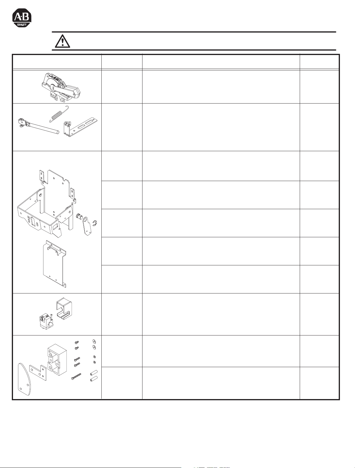
Components Cat No. Description
1494F-M1
1494F-P1
1494F-S1
1494V-RA3
1494V-RA4
5-1/2" Painted Metal Handle
5-1/2" Molded Handle
5-1/2" Stainless Steel Handle
Standard Connecting Rod
Enclosure Working Depth: 6-3/4" to 9-1/8"
Extended Connecting Rod
Enclosure Working Depth: 9-1/8" to 23"
Circuit breaker mechanism for use with
1494V-M41
Allen-Bradley: 140U-H (MCCP), 140M-H (MCP)
Cutler-Hammer: EF, HMCPE
Circuit breaker mechanism for use with
1494V-M40
Allen-Bradley: 140M-I (MPCP and MCP)
Cutler-Hammer: EHD, FD, FDB, FDC, HFD, HMCP
Circuit breaker mechanism for use with
1494V-M51
Allen-Bradley: 140U-J (MCCB), 140M-J (MPCB and MCP)
Cutler-Hammer: EF
Switch Rating
(Amps)
125A...400A
125A...400A
125A
150A
250A
Circuit breaker mechanism for use with
1494V-M50
Cutler-Hammer: JD, JDB, JDC, HJD, HMCP
250A
Circuit breaker mechanism for use with
1494V-M60
Allen-Bradley: 140U-K (MCCB), 140M-K (MPCB and MCP)
400A
Cutler-Hammer: KD, KDB, KDC, HKD, HMCP
TERMINAL
GUARD
N.O.
1495-N8
1495-N9
(1) N.O. Auxiliary Contact
125A...400A
(1) N.C. Auxiliary Contact
1495-N21 Auxiliary Contact Adapter Kit 125A...150A
1495-N23 Auxiliary Contact Adapter Kit 250A...400A
42052-074-01 (1)
Printed in U.S.A.
Page 2
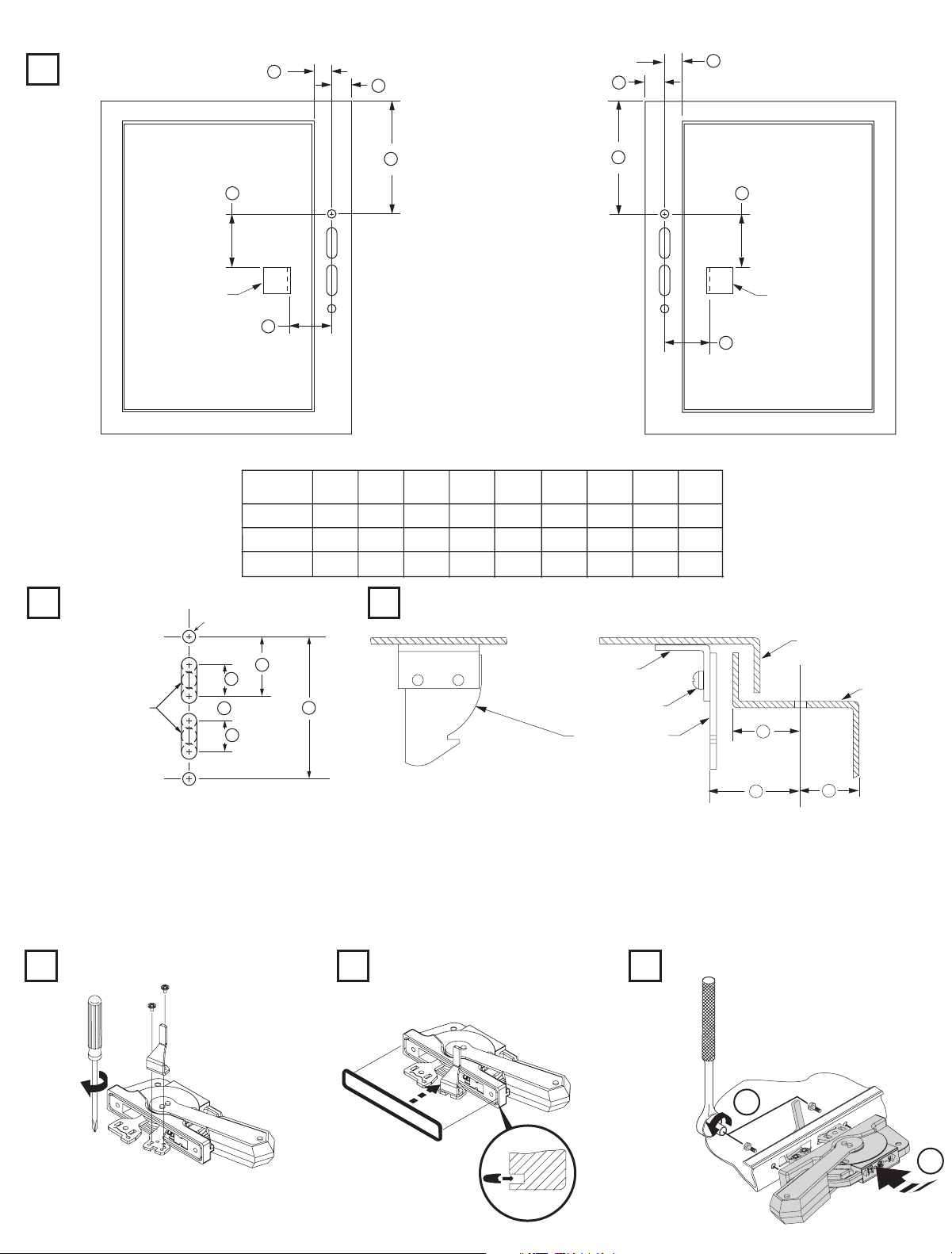
Handle Installation
Locate Handle
1
C
B
B
C
Drill Handle Holes
2
To make slot drill
(3) 1/2" diameter holes
and remove burrs
E
Door Catch
Mounting
Bracket
D
Right Hand-Flange
FRAME
SIZE
125A, 150A
250A
400A
(2) .265 Dia. Holes
G
H
J
H
(min)
3 - 1/2"
10 - 29/32"
13 - 3/32"
F
A
A
E
Door Catch
Mounting
D
Bracket
Left Hand-Flange
D
E
F
G
H
A
(max)
(min)
1 - 3/32"
29/32"
1 - 3/32"
29/32"
1 - 3/32"
29/32"
Locate Door Catch
3
1 - 5/8"
1 - 5/8"
1 - 5/8"
2 - 11/32"
2 - 11/32"
2 - 11/32"
4 - 11/16"
4 - 11/16"
4 - 11/16"
1 - 9/16"
1 - 9/16"
1 - 9/16"
C
B
Door Catch
Mounting Bracket
30 lb-in
Door Catch
J
1"
7/8"
1"
7/8"
1"
7/8"
Enclosure Door
Enclosure
Base
C
Notes:
D
B
A) Enclosures with a Flange Thickness less than 3/16" use dimensions above.
B) Enclosures with a Flange Thickness 3/16" and greater use dimensions in Mounting Kit 1494V-H3.
C) Multi-Door Enclosures use dimensions in Channel Support Kit 1494V-H4, if handle is mounted atop channel.
D) The door catch mounting bracket is provided with projections for welding; however, holes can be drilled in the bracket using the
projections for locating hole centers. After proper location, use the bracket as a template and drill corresponding holes in the
enclosure door. Fasten the bracket with hardware supplied by user. If properly assembled, the hardware should not be accessible for
tampering with by unauthorized personnel.
Install Defeater Lever
4
7-11 lb-in
Install Gasket
5
Install Handle to Flange
6
2
23-37 lb-in
(2)
1
Page 3

Circuit Breaker Mechanism Installation
1 2
1494V-M41
1494V-M51
(Only)
2
1
16 - 22 lb-in
3
LL
3
Threaded Rod
N
Enclosure
Working Depth
(Flange to
Mounting Plate)
Connecting
Rod
Standard
Extended
Catalog Number
1494V-RA3
1494V-RA4
N - 3"
"N"
Min. Max.
6-3/4" 9-1/8"
9-1/8" 23"
Locate Circuit Breaker Mechanism (125A and 150A Frame Circuit Breakers)
4a
AAAAAAAAAABB
CC
EE
AA
DD
Frame
Size
125A
150A
AA BB CC DD
1/4" 2 - 7/64" 1 - 3/8" 4 - 1/2"
1/4" 2 - 7/64" 1 - 3/8" 4 - 1/2"
EE
Wire
Bending
Space
6
6
Mechanism
Mounting
Hole (Tapped)
KK
(4) - #8-32
(4) - #8-32
AAAAAAAAAA
BB
Left Hand-FlangeRight Hand-Flange
Mechanism
Mounting
Hole (Tapped)
lb-in
20
20
CC
(3)
Page 4

Circuit Breaker Mechanism Installation (Cont'd)
Locate Circuit Breaker Mechanism (250A and 400A Frame Circuit Breaker)
4b
BB
CC
BB
CC
Frame
Size
250A
400A
MM
HH
EE
DD
KK
JJ
AA BB CC DD
13/16" 2 - 9/32" 1 - 3/8" 7 - 1/4" - - - - - 1 - 7/32" - - - - -
- - - - - 2 - 13/16" 1 -23/32" - - - - - 8 - 7/16" 1 - 13/32" 1/4"
LL
EE FF GG
GG
FF
GG
AA
HH
10 - 5/8"
10 - 3/4"
MM
LL
2 - 31/32"
3 - 43/64"
LL
MM
Wire
Bending
Space
10
12
HH
EE
DD
KK
JJ
Left Hand-FlangeRight Hand-Flange
Mechanism
Mounting
Hole (Tapped)
JJ
(2) - #10-32 (4) - 1/4-20 60
(2) - #10-32 (4) - 1/4-20 60
Mechanism
Mounting
Hole (Tapped)
KK
Hole (Tapped)
Mechanism
Mounting
lb-in
5
6
2
On
Off
Toggle
Adjustment
Plate
UP
1
3
16 - 20 lb-in
Toggle
Adjustment
Plate
25 - 30 lb-in
150A
125A
(4)
125A / 150A
Circuit Breaker
250A / 400A
Circuit Breaker
Page 5

Circuit Breaker Installation (Cont'd)
2
87
2
3
1
3
1
Hitch Pin
Testing of Circuit Breaker
1. Verify that the circuit breaker can be turned on by moving the defeater lever downward and moving the disconnect
handle to the ON position.
2. If the circuit breaker does not turn on, loosen the (2) screws and adjust the toggle adjustment plates toward the line
terminals until the circuit breaker turns on when the disconnect handle is in the ON position. Tighten the (2) toggle
adjustment plate screws to 25 - 30 lb-in.
3. If the circuit breaker still can not be turned on unhook the spring, remove hitch pin and separate threaded rod and
handle link. Turn threaded rod one full turn counterclockwise. Reattach threaded rod and handle link, hitch pin and
spring. Repeat Step 1 and if necessary Step 2.
4. Verify that the circuit breaker can be turned off by moving the disconnect handle to the OFF position.
5. If the circuit breaker can not be turned off, loosen the (2) screws and adjust the toggle adjustment plates toward the
load terminals until the circuit breaker turns off when the disconnect handle is in the OFF position. Tighten the (2)
toggle adjustment plate screws to 25 - 30 lb-in.
6. If the circuit breaker still can not be turned off and if no adjustment of the threaded rod was made in Step 3 then
unhook the spring, separate threaded rod and handle link and remove hitch pin. Turn threaded rod one full turn
clockwise. Reattach threaded rod and handle link, hitch pin and spring. Repeat Step 4 and if necessary Step 5.
7. Verify that the circuit breaker can be reset after manually tripping when circuit breaker is in the ON position.
8. Manually trip the circuit breaker while in the ON position, then move the disconnect handle to the Off-Reset
position.
9. If the circuit breaker does not reset, loosen the (2) screws and adjust the toggle adjustment plates in small
increments toward the load terminals.
Note: Repeat this procedure until the circuit breaker can be reset.
Note: Do not adjust the toggle adjustment plate too far: this will prevent the disconnect handle from moving to the full OFF-
Reset position.
10.Tighten the (2) adjustment plate screws to 25 - 30 lb-in.
11.Verify that the circuit breaker can still be turned on following the above steps.
Note: Twisting of the bail mechanism is acceptable when the handle is in the full ON or full OFF position.
4
(5)
Page 6

Auxiliary Installation
Safety Guards
On
Off
5
Bulletin 1495
1
Auxiliary
Contacts
Slot B
Slot A
Base
Assembly
3
Bail
Support
Bracket
4
Support
Bushings
Plate
Safety Guard
Cam
2
Bulletin 1495
Auxiliary
Contacts
1. Move the disconnect handle on the combination starter to the OFF position.
2. Fasten the cam and bushings to the bail with (2) flat washers, (2) lock washers, and (2) screws Tighten to 12 - 16 lb-in.
3. Fasten the base assembly to the support bracket with (2) screws. Tighten to 7 - 10 lb-in.
4. Attach the assembly from Step 3 to the ear on the support plate with (2) screws. Tighten to 7 - 10 lb-in.
5. Attach the auxiliary contact with the safety guard to the base assembly.
Note: If a single auxiliary contact is used, it must be positioned nearest the cam, in slot A shown above. A second auxiliary contact
would be positioned in slot B.
Testing of Auxiliary Contacts
1. Make sure the auxiliary contact and adapter kit (circuit breaker) have been installed in the proper position.
2. If the auxiliary contact (circuit breaker) is N.O., place the probes of the continuity tester across both terminals with the
disconnect handle in the OFF position; there should be no continuity.
3. Move the disconnect handle to the ON position and place the probes of the continuity tester across both terminals; there
should be continuity.
4. If the auxiliary contact (circuit breaker) is N.C., place the probes of the continuity tester across both terminals with the
disconnect handle in the OFF position; there should be continuity.
5. Move the disconnect handle to the ON position and place the probes of the continuity tester across both terminals; there
should be no continuity.
42052-074-01 (1)
Printed in U.S.A.
 Loading...