

Page 1
Installation Instructions
Bulletin 1494U Universal Disconnect Switch Installation Instructions (30A, 60A, 100A)
(Cat 1494U-D30; 1494U-D60; 1494U-D100; Series A)
WARNING: To prevent electrical shock, disconnect from power source before installing or servicing. Follow NFPA 70E requirements. Install in suitable enclosure. Keep free from contaminants.
Installation, adjustments, putting into service, use, assembly, disassembly, and maintenance shall be carried out by suitably trained personnel in accordance with applicable code of practice. In case of malfunction or
damage, no attempts at repair should be made. The product should be returned to the manufacturer for repair. Do not dismantle the product.
WARNING: The following procedures are critical to the proper operation of the disconnect handle and switch. Failure to follow these steps can result in damage to the equipment and/or serious injury or death to the operator.
Tools Needed: 7/16” Nut Driver, 5/16” Nut Driver, Hammer, Center Punch, File, T27 Torx Driver, Phillips Screwdriver, 11/64” Drill Bit, Needlenose Pliers
Table of Contents Page
Installation Guide............................................................................................................................................................................. 2
Rod and Cable Operated Disconnect Switch Location.................................................................................................. 2
Rod Operated Switch Installation.......................................................................................................................................... 3
Handle Installation.................................................................................................................................................................. 3
Connecting Rod Installation................................................................................................................................................ 3
Rod Adjustment Procedure................................................................................................................................................. 4
Cable Operated Switch Installation...................................................................................................................................... 5
Handle and Cable Mechanism Installation..................................................................................................................... 5
Cable to Switch Mechanism Installation......................................................................................................................... 6
Cable Adjustment Procedure.............................................................................................................................................. 7
Enclosure Without Handle Cutout............................................................................................................................................. 8
Door Catch Bracket Installation.................................................................................................................................................. 9
Trailer Fuse Block and Phase Barrier Installation................................................................................................................10
Auxiliary Contact Installation.....................................................................................................................................................11
Line Terminal Adapter Installation..........................................................................................................................................12
Fuse Clip and Fuse Installation.................................................................................................................................................13
Protective Cover Installation.....................................................................................................................................................14
Bulletin 1494U Disconnect Switch Component Accessory List....................................................................................15
PN-224754
DIR 10001182729 (Version 01)
Printed in U.S.A.
Page 2
Rod and Cable Operated Disconnect Switch Location
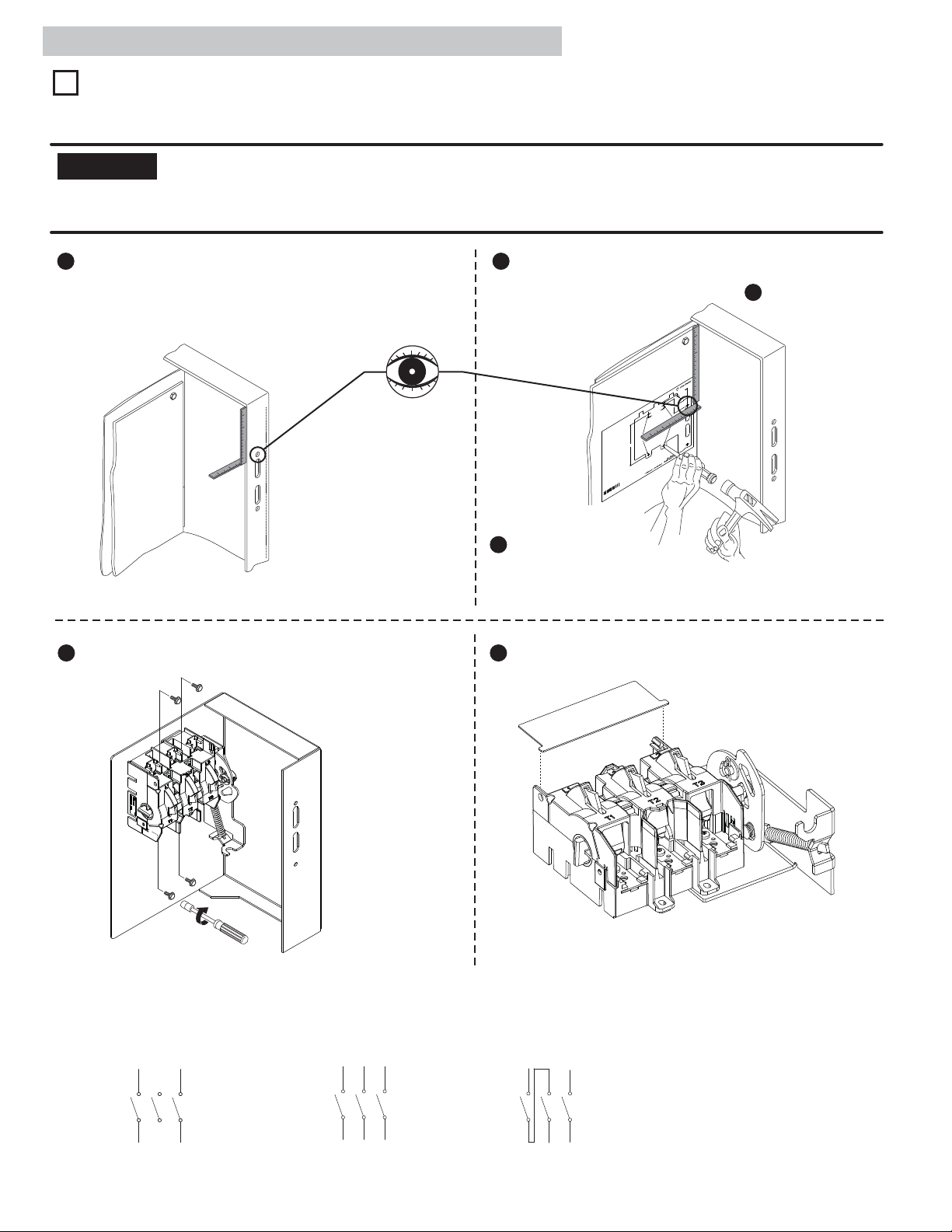
Disconnect Switch Location and Installation
1
A) For Rod Operated Switches, follow steps 1 - 5 below.
B) For Cable Operated Switches, follow steps 3 - 5 below.
NOTICE
between the switch mechanism and handle mechanism is not less than 6 inches.
Any reduction to the diameter of the bend loop for the cable will reduce the efficiency of the cable system, create additional drag and friction within
the cable conduit and possibly decrease system life.
When locating the 30A, 60A and 100A cable operated switch, verify that the minimum diameter for the loop of the cable
1 Measure top hole of handle on enclosure.
2 Use template PN-254969 to locate handle holes on mounting plate.
Lay template on enclosure back plate. Align using the top hole on
Measure hole center to side of enclosure: _______
paper and measurements taken from step .
1
Measure hole center to top of enclosure: _______
2-7/8
1-3/4
ead
1-13/16
r
or th
used
2
e
l
Switch Mounting Holes
AP-TITE) sc
er punch and drill (4) 11/64" holes f
t
(T
en
C
forming
empl
ation T
oc
Variable Depth Disconnect S
Hole L
ews pro
r
ate (30A - 60A - 100A
vided with switch
witch
Ho
or Step
f
)
St
of h
Ste
nc
e
and align by u
top hole
mea
from Step 1
Step 3
down, pu
holes
54969
0
PN-2
00
1
© 201
t
R
h
g
DI
ri
y
p
o
C
p 1: Measure top hol
e
dle
an
Measure ho
·
side of
Measure h
·
top of enc
p 2: Lay
losure ba
surements taken
:
Vers
(
to
Au
9
l
5
l
e
03
ckw
o
12
R
1
4
e
enter to
e c
l
e
on enclosure
losur
nc
e
ole center to
e
r
osu
l
te
mplate on
4-7/8
e
e
t
ck pla
nd
sing th
on paper a
l
e template
, and dril
Tap
h
nc
.
A
US
in
d
Printe
.
Reserved
Rights
)
ll
A
00
n
Inc.
,
io
on
ti
ma
3 Tape template down.
Center punch and drill (4)
11/64” holes for thread
forming (TAP-TITE) screws
provided with switch.
4 Install Disconnect Switch. 5 Install Line Terminal Guard.
23 - 37 lb-in
7/16” Nut Driver
Wiring Diagrams
Single Phase AC Three Phase AC Direct Current
L1 L2 L3
L1 L2 L3
L1 L2 L3
T1 T2 T3
PN-224754
DIR 10001182729 (Version 01)
T1 T2 T3
T1 T2 T3
(2)
Page 3
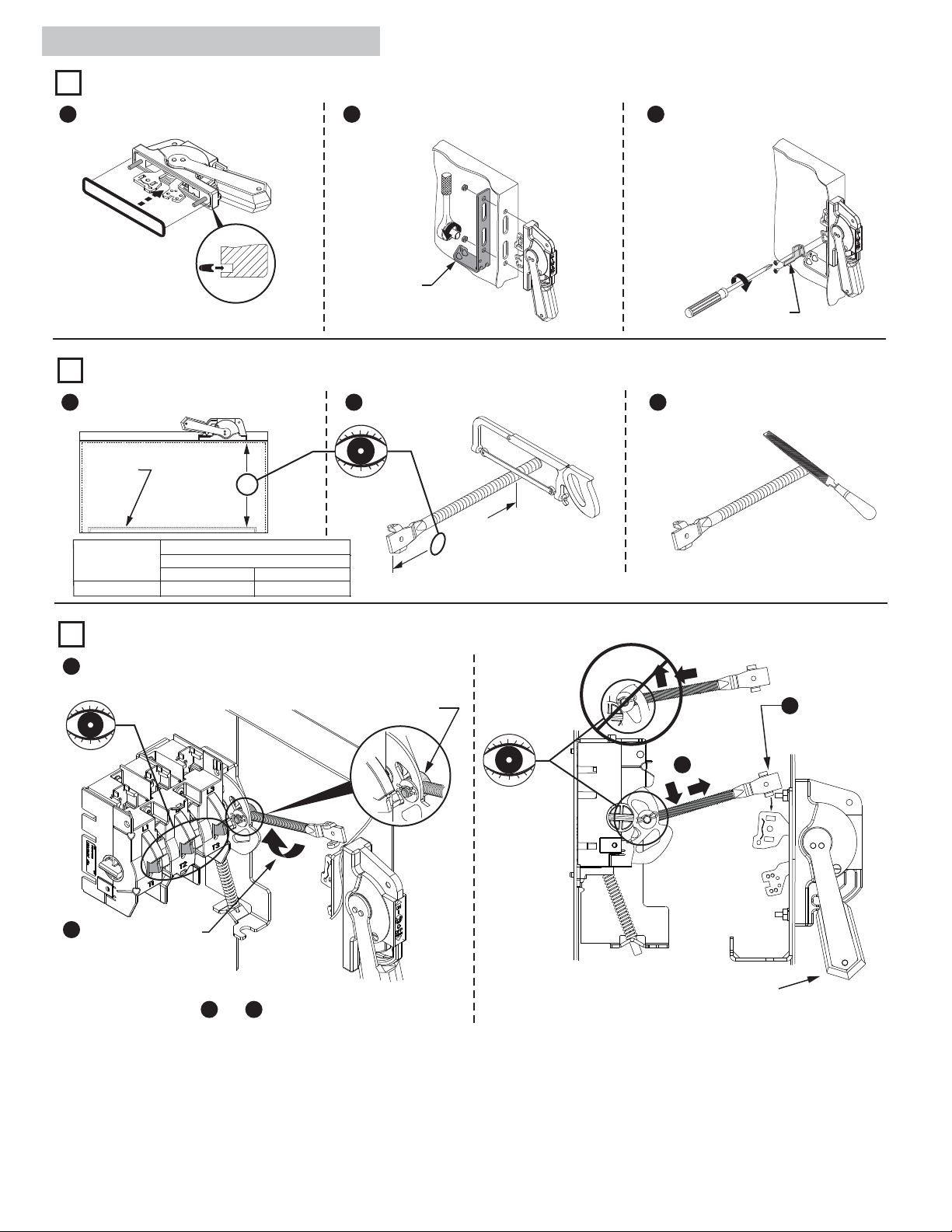
Rod Operated Switch Installation
Handle Installation
1
1 Install gasket. 2 Install spring bracket and handle.
30 - 40 lb-in
Spring
Bracket
Cutting Connecting Rod
2
3 Install defeater lever.
7 - 11 lb-in
1 Measure working depth of enclosure. 2 Measure, mark and cut connecting rod. 3 Remove burrs.
Mounting
Plate
Connecting Rod
1494U-R1
Enclosure
Working Depth
(Inside Flange
of Enclosure to
Mounting Plate)
30A - 60A - 100A Disconnect Switches
Enclosure Working Depth “N”
6-1/2”
Min.
N
Max.
19”
N minus 3"
For enclosures with a working depth greater than 19”
but less than 23”, use connecting rod kit 1494V-RA4.
Defeater
Lever
Connecting Rod Installation
3
1 Verify that disconnect switch and handle are in “OFF” position
(Switch blades will be visible).
Drive Bar
2
2
Rotate connecting rod
into drive bar (11) full
turns.
See steps and for final rod alignment.
2
2
3
4
3
Ensure that the handle is
in the full “OFF” position.
Align threaded rod
toward handle and,
4
if needed, rotate
counterclockwise
until ears engage the
primary link slots.
PN-224754
DIR 10001182729 (Version 01)
(3)
Page 4
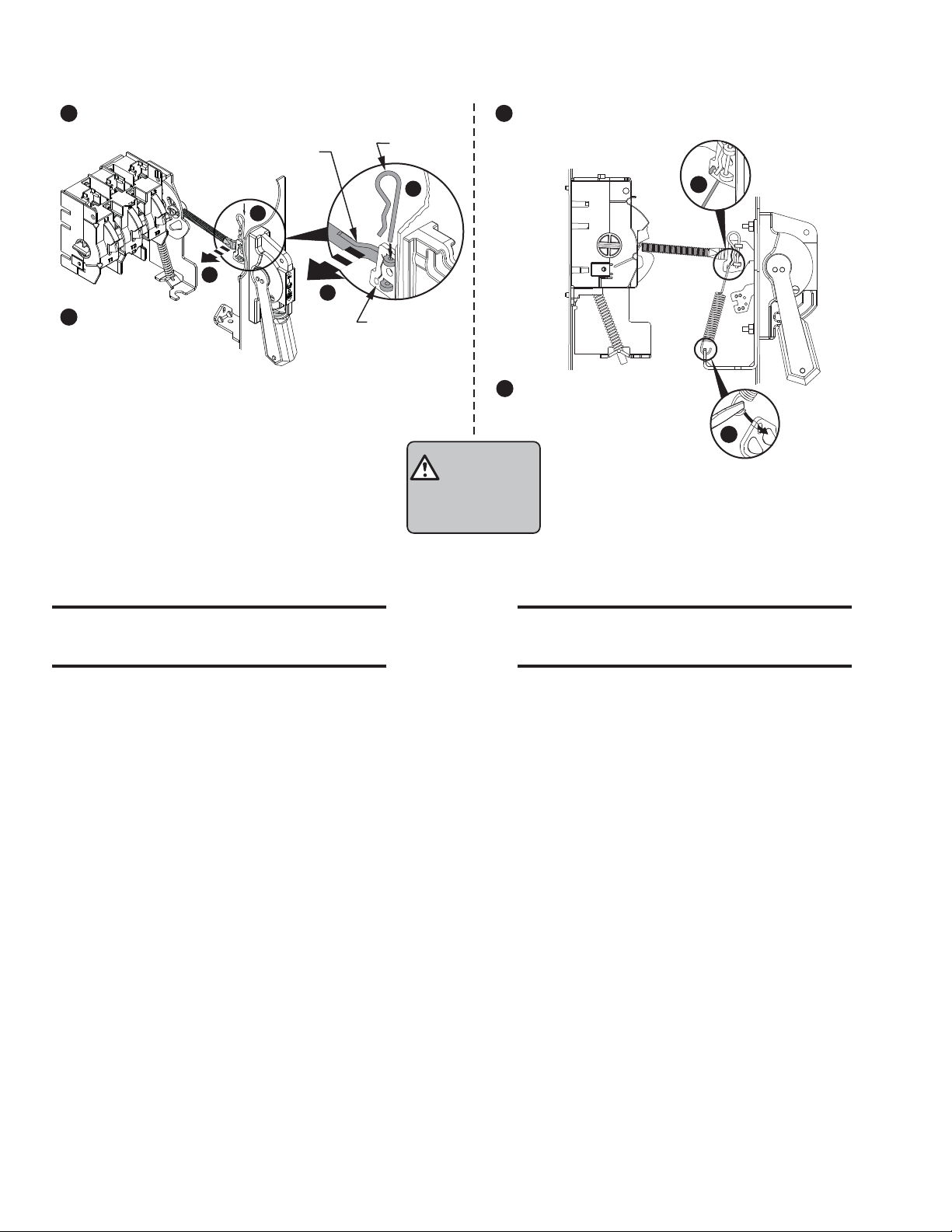
5 Engage ears of connecting rod into slots of handle link. 7 Install spring to handle link.
Connecting
6
5
6 Install hitch pin
through ears of
connecting rod.
Rod Adjustment Procedure
Rod
Hitch Pin
6
5
Primary Link
8 Install other side of spring
to handle bracket.
7
8
ATTENTION
CHECK FOR PROPER
OPERATION
Adjustment Procedure if switch does not
turn "ON".
1. Move handle to “ON” position.
2. If switch does not fully close, return handle to
"OFF" position.
3. Remove link spring and hitch pin to disengage
the connecting rod from the primary link.
4. Turn connecting rod counter-clockwise (1 or
more) full turns.
5. Re-engage connecting rod in primary link of
handle, insert hitch pin and re-test.
6. Repeat steps 1 - 5 as necessary.
7. Re-install link spring.
Adjustment Procedure if switch does not
turn "OFF".
1. Move handle to “OFF” position.
2. If switch does not fully open, return handle to
"ON" position.
3. Remove link spring and hitch pin to disengage
the connecting rod from the primary link.
4. Turn connecting rod clockwise (1 or more) full
turns.
5. Re-engage connecting rod in primary link of
handle, insert hitch pin and re-test.
6. Repeat steps 1 - 5 as necessary.
7. Re-install link spring.
PN-224754
DIR 10001182729 (Version 01)
(4)
Page 5
Cable Operated Switch Installation
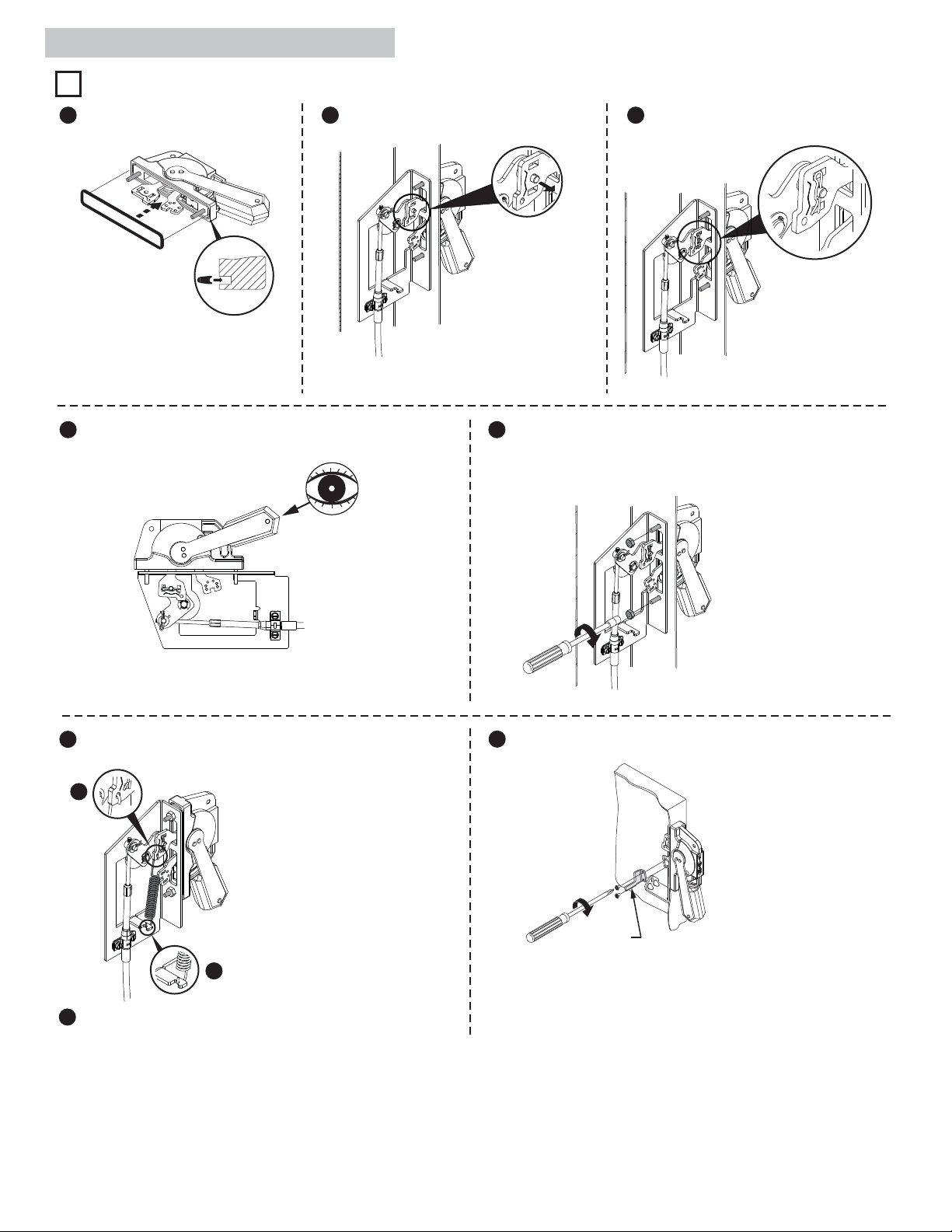
Handle and Cable Mechanism Installation
1
1 Install gasket. 2 Connect handle link to lever pin. 3 Install hitch pin through handle link.
TIP: Move handle to
“ON” position to help
connect handle link
to lever pin. Return
handle to “OFF”
position once
connected.
4 Verify handle is in “OFF” position.
6 Install spring to handle link.
6
5 Install handle nuts.
30 - 40 lb-in
8 Install defeater lever.
7
7 Install other end of spring to cable mechanism bracket
using needlenose pliers.
PN-224754
DIR 10001182729 (Version 01)
7 - 11 lb-in
Defeater
Lever
(5)
Page 6

Cable to Switch Mechanism Installation
2
NOTICE
from all heat sources and current carrying terminals, fuses, transformers, etc.
When locating the 30A, 60A and 100A switch, verify that the minimum diameter for the loop of the cable between the switch
Verify that the cable assembly does not interfere with any mechanical and moving parts. Keep the cable conduit a minimum of 1/2”
IMPORTANT
mechanism and the handle mechanism is not less than 6 inches.
1 Locate switch as to not pinch the cable or create
a bend less than 6” in diameter.
NOTE:
All bends must be
greater than 6” in
6” Diameter Min
diameter.
Do Not Pinch Cable
1 Tighten cable nuts onto switch
bracket.
Check for one
washer on each
side of the switch
bracket.
30 - 35 lb-in
2 Use washer and hitch pin to attach cable
pivot to switch mechanism cable slot.
Install pin as
shown. Do
not push past
second bend
on clip.
3 Remove drive bar for rod operation, washer
and hitch pin; discard.
PN-224754
DIR 10001182729 (Version 01)
(6)
Page 7

Cable Adjustment Procedure
1 Move handle to “ON” position. 2 Remove cable pivot hitch pin and washer. 3 Push cable pivot out of handle bracket.
4 Return handle to “OFF” position. 5 (a) ADJUSTMENT PROCEDURE IF
SWITCH DOES NOT FULLY CLOSE
Unscrew cable pivot ONE full turn
counter-clockwise to extend cable.
6 Return handle to “ON” position and insert
cable pivot back into mechanism.
7 Re-install cable pivot washer and hitch pin. 8 Confirm switch operates properly and
5
(b) ADJUSTMENT PROCEDURE IF
SWITCH DOES NOT FULLY OPEN
Turn cable pivot ONE full turn
clockwise to shorten cable.
repeat steps 5-7 if necessary.
PN-224754
DIR 10001182729 (Version 01)
(7)
Page 8

Enclosure without Handle Cutout
• Multi-Door Enclosures may require the need for a more rigid flange / mounting plate system, such as a Channel
Support Kit. Use dimensions in Channel Support Kit 1494V-H15 if handle is mounted on top of the channel.
• Some Enclosures with hinged flange panels may require additional flange support brackets to stiffen panel.
Consult your local enclosure manufacturer.
Locate Handle
1
Right Hand Flange
Drill Handle Holes
2
C
B
A
B
A
C
Top Handle Hole
Left Hand Flange
To make slot drill (3) 1/2" diameter holes and remove burrs
PN-224754
DIR 10001182729 (Version 01)
NEMA
SIZE
30A, 60A
100A
Top Handle Hole
A
(min)
4 - 5/8"
6 - 1/16"
(min)
1 - 1/8"
1 - 1/8"
(2) .265 Dia. Holes
G
H
J
H
Enclosure Dimensions
B
C
(max)
1 - 1/16"
1 - 1/16"
(8)
F
4 - 11/16"
4 - 11/16"
F
G
1 - 9/16"
1 - 9/16"
H
1"
1"
J
7/8"
7/8"
Page 9

Door Catch Bracket Installation
Right hand installation shown (for left hand installation follow similar procedures)
Door Catch Mounting Bracket:
• Provided with projections for welding.
• Projections can also be used as a guide for drilling holes.
• Can be used as a template to drill corresponding holes in the enclosure door.
• User to supply the hardware for fastening the bracket.
• The bracket hardware must be inaccessible to unauthorized personnel.
• Fasteners must provide the degree of ingress protection for the environmental rating of the enclosure.
Dimension K (3/4" to 1")
• When using small disconnect handle kit only (1494U-HP1, -HM1 or -HS1), use door catch provided with handle kit.
• When using small disconnect handle kit and small door hardware kits (1494V-L1, -LL1, -L2 or -LL2), use door catch
provided with door hardware kit.
Dimension K (1-1/8" to 1-3/8")
• When using small disconnect handle kit only (1494U-HP1, -HM1 or -HS1), use door catch (40492-080-02) which can be
ordered from factory.
• When using small disconnect handle kit and large door hardware kits (1494V-L3 or -LL3), use door catch provided with
door hardware kit.
Door Catch
Mounting Bracket
Top
Enclosure Door
Door Catch
Mounting Bracket
Door Catch
NEMA
SIZE
30A, 60A
100A
C
E
TOP VIEW
A
(min)
4 - 5/8"
6 - 1/16"
B
(min)
1 - 1/8"
1 - 1/8"
B
C
D
Enclosure Dimensions
C
(max)
1 - 1/16"
1 - 1/16"
A
D
1 - 5/8"
1 - 5/8"
2 - 3/8"
2 - 3/8"
Top Handle Hole
B
E
Flange
Thickness
Enclosure
F
4 - 11/16"
4 - 11/16"
Base
G
1 - 9/16"
1 - 9/16"
B
A
Door Catch
K
H
1"
1"
J
7/8"
7/8"
C
E
Door Catch
Mounting
Bracket
Right Hand Flange Left Hand Flange
PN-224754
DIR 10001182729 (Version 01)
Door Catch
Mounting
D
D
(9)
Bracket
Page 10

Trailer Fuse Block and Phase Barrier Installation
Fuse
A
Torque (lb-in)
Phase
Barrier
Amps
Volts
Class
Fuse
Block
Fuse
Clip
Lug to
Terminal
Wire
Into Lug
30
250*
H/R
23-37
23-37
40-60
45
**
30
600
H/R
B
30
600
J
**
30
600
HRCII-C
A
60
250
H/R
A
60
600
H/RB60
600
J**60
600
HRCII-C
A
100
250
H/R
16-22
50
C
100
600
H/R
D
100
600JB
100
600
HRCII-C
B
(1) 14 AWG … 2 AWG ( Cu - Al )
1494U-LA36 Si ngle port 30 ... 60 Al
Cu - Al 45 (2) 14 A WG … 10 AWG (Cu)
(2) 12 AWG …10 AWG ( A l )
(2) 12 AWG … 4 AWG ( Cu - Al )
1494U-LA100 Si ngle port 100 Al
Cu - Al 50 (1) 14 A WG … 1/0 AWG (Cu)
(1) 12 AWG …1/0 AWG (Al)
(1) 10 AWG (Cu - Al)
1494U-LM36 MulƟ-port 30 ... 100 Al
Cu - Al (2) 14 AWG … 4 A WG (Cu)
(2) 12 AWG … 14 AWG ( A l )
(1) 14 AWG … 4 AWG ( Cu)
1494U-LC36 Single port 30... 60 Cu
Cu onl y 45 (2) 14 A WG … 8 AWG (Cu)
(4) 16 AWG (Cu)
Wire
Range
45 for 30/60
50 for 100
Catalog
Number
Lug
DescripƟon
Lug
Amps
Lug
Material
Wire
Material
Torque
Wire into Lug
1 Trailer Fuse Block Location
A
**Phase barrier not required.
1.791
4.585
1.791
3.024
2.622
5.122
1.976
3.024
5.636
7.636
4.449
4.402
2 Snap phase barrier off to desired length as shown in table above.
D
C
B
A
Lug Connectors
3 Slide phase barriers into fuse block and click in place.
Click
PN-224754
DIR 10001182729 (Version 01)
(10)
Page 11

4 Slide phase barriers into channels on switch.
5 Fasten fuse block to panel.
23 - 37 lb-in
Auxiliary Contact Installation
1
2
CLICK
8 mm
1
0.75 - 2.5 mm²
(#18 - #12 AWG)
0.7 - 0.9 Nm
6 - 8 lb-in
2
PN-224754
DIR 10001182729 (Version 01)
(11)
Page 12

Auxiliary Contact Wire Routing
Wire routing channels
Wire tie-down points
Line Terminal Adapter Installation
Load Side
Line Side
Wire Clamp
Adapter
Wire Lug
Lug Adapter Kit
Catalog
Number
1494U-ALT31 30A/60A/100A 25-28 25
Disconnect
Switch
Rating (Size)
Adapter
Torque
(Lb.-In.)
Wire
Clamp
Torque
(Lb.-In.)
Wire Clamp
Wire Range
(1) 14-10 STR/SOL
(1) 8 STR
(2) 14 SOL/SOL
(2) 14 STR/STR
(2) 12 SOL/SOL
(2) 12 STR/STR
(2) 10 SOL/SOL
(2) 10 STR/STR
(2) 8 STR/STR
PN-224754
DIR 10001182729 (Version 01)
(12)
Page 13

Fuse Clip and Fuse Installation
30A/60A Fuse Clip Installation 30A/60A Fuse Installation
100A Fuse Clip Installation 100A Fuse Installation
PN-224754
DIR 10001182729 (Version 01)
(13)
Page 14

Protective Cover Installation
1 Position cover in front of switch as shown. 2 Spread sides apart at bottom to fit around fuse block.
3 Rotate cover up and slide top sides into tracks shown on switch.
Push in until fully inserted and pull cover down slightly to ensure
engagement.
5 Ensure flange on left side of cover has snapped under fuse block.
4 Press center of cover tight to mounting plate to engage notch in right
side of cover with switch bracket.
6 Optional: Install high-vibration application screw in bottom slot.
PN-224754
DIR 10001182729 (Version 01)
(14)
Page 15

Bulletin 1494U Disconnect Switch Component Accessory List
Component
Cat No.
Switch and Mechanism
1494U-D30 (30A)
1494U-D60 (60A)
1494U-D100 (100A)
Includes:
Line Side Lugs (Field Installed)
Line Side Shield (Field Installed)
Load Side Lugs (Field Installed)
1494U-AL36 (30A/60A) (Pkg Qty 3)
1494U-AL100 (100A) (Pkg Qty 3)
1494U-HM1 (5-1/2” Painted Metal) (30A - 200A)
1494U-HP1 (5-1/2” Molded Plastic) (30A - 200A)
1494U-HS1 (5-1/2” Stainless Steel) (30A - 200A)
1494U-R1 (30A-100A)
Enclosure Working Depth: 6-1/2” to 19”
Fuse Clip Kits (Pkg Qty 6):
1494U-FC302J (30A 250V Class J)
1494U-FC302R (30A 250V Class R)
1494U-FC30J (30A 600V Class J)
1494U-FC60J (60A 600V Class J)
1494U-FC100J (100A 600V Class J)
1494U-FC30R (30A 600V Class R)
1494U-FC60R (60A 600V Class R)
1494U-FC100R (100A 600V Class R)
Disconnect Switch and Mechanism
(1494U-D30 shown)
Handle
(1494U-HM1 shown)
Connecting Rod
Cable-Operated Handle Mechanism
Fuse Block
(1494U-F30 shown)
Fuse Clip Kits
Cable Handle Mechanism:
1494U-C313 (3 ft. Cable)
1494U-C314 (4 ft. Cable)
1494U-C315 (5 ft. Cable)
1494U-C316 (6 ft. Cable)
1494U-F30 (30A)
1494U-F60 (60A)
1494U-F100 (100A)
Includes:
Phase Barriers
1494U-PB31 (Field Installed) (Pkg Qty 2)
PN-224754
DIR 10001182729 (Version 01)
(1494U-FC30J shown)
(15)
Page 16

Auxillary Contacts
1494U-NO (1 N.O.)
1494U-NC (1 N.C.)
1494U-NOLV (1 N.O. Low Level)
1494U-NCLV (1 N.C. Low Level)
Aluminum Lugs
Copper Lugs
1494U-LC36 (30A - 60A)
1494U-LC100 (100A)
(Pkg Qty 3)
Multiport Lugs
1494U-LM31 (30A - 100A)
(Pkg Qty 3)
Line Terminal Adapters
1494U-ALT31 (Pkg Qty 2)
250V
600V
30/60/100A
Non-
Fusible
30A
30A
30A
60A
100A
30A
60A
100A
1494U-LA36 (30A - 60A)
1494U-LA100 (100A)
(Pkg Qty 3)
(1494U-LA100 shown)
(1494U-LC100 shown)
Phase Barriers
1494U-PB31 (Pkg Qty 2)
Fuse Cover
Rockwell Automation maintains current product environmental information on its website at http://ww w.rockwellautomation.com/rockwellautomation/about-us/sustainability-ethics/product-environmental-compliance.page.
Allen-Bradley, Rockwell Software, and Rockwell Automation are trademarks of Rockwell Automation, Inc.
Trademarks not belonging to Rockwell Automation are propert y of their respective companies.
Switch
Rating
Fuse
Class
H,J
R
H,J
H,J
H,J
R
R
R
Fuse Clip Rating
----
----
30A
30A
----
----
----
----
----
----
----
----
30A
60A
100A
30A
60A
100A
1494U-F302J
1494U-F302R
1494U-FC30J
1494U-FC60J
1494U-FC100J
1494U-FC30R
1494U-FC60R
1494U-FC100R
Fuse Clip
Cat No.
----
Fuse Cover
Cat No.
1494U-PC1
1494U-PC2
Publication 1494U-IN001B-EN-P - September 2014
Copyright © 2014 Rockwell Automation, Inc. All Rights Reserved. Printed in USA.
DIR 10001182729 (Version 01)
PN-224754
 Loading...