

Page 1

Bulletin 1494F Fixed Depth Disconnect Switch Installation Instructions
(Cat 1494F-N30; -N60; -N100; -N200) (Series B)
WARNING
WARNING
To prevent electrical shock, disconnect from power source before installing or servicing. Follow
NFPA 70E requirements. Install in suitable enclosure. Keep free from contaminants.
The following procedures are critical to the proper operation of the disconnect handle and switch.
Failure to follow these steps can result in damage to the equipment and/or serious injury or death to the
operator.
Table of Contents Page
Enclosure with Pre-Drilled Handle Cutout 2
Install Disconnect Switch
-
- Install Disconnect Switch Standoffs
Enclosure without Pre-Drilled Handle Cutout
Locate Handle
-
3
- Drill Handle Holes
Enclosure Requiring Door Catch Mounting Bracket
4
Fuse Block Adapter Plate Installation (Switch Rating 30A - 60A - 100A) 5, 6
Fuse Block Adapter Plate Installation (Switch Rating 200A) 7
Phase Barrier Replacement Kit and Fuse Clip Installation
(
Switch Rating 30A - 60A) 8
Phase Barrier Replacement Kit and Fuse Clip Installation
(
Switch Rating 100A) 9
Phase Barrier Replacement Kit (
Switch Rating 200A) 10
Fuse Clip Installation (
Switch Rating 200A)
11
Dimensions 12
Fuse Clip Installation (200A)
Installation--Vault Hardware Latching (1494F-L1)
12
13
Installation-- Vault Hardware Latching (1494F-L2, -L3, -L4) 14
Testing Vault Hardware Latching and Enclosure Seal 15
Installation-- Vault Hardware Latching (Non Pre-Drilled Enclosures) 16, 17
Bulletin 1494F Disconnect Switch Kits 18
Bulletin 1494F Disconnect Switch Kit Optional Accessory List 19
42052-195-01
DIR 10000075001 (Version 00)
Printed in U.S.A.
Page 2
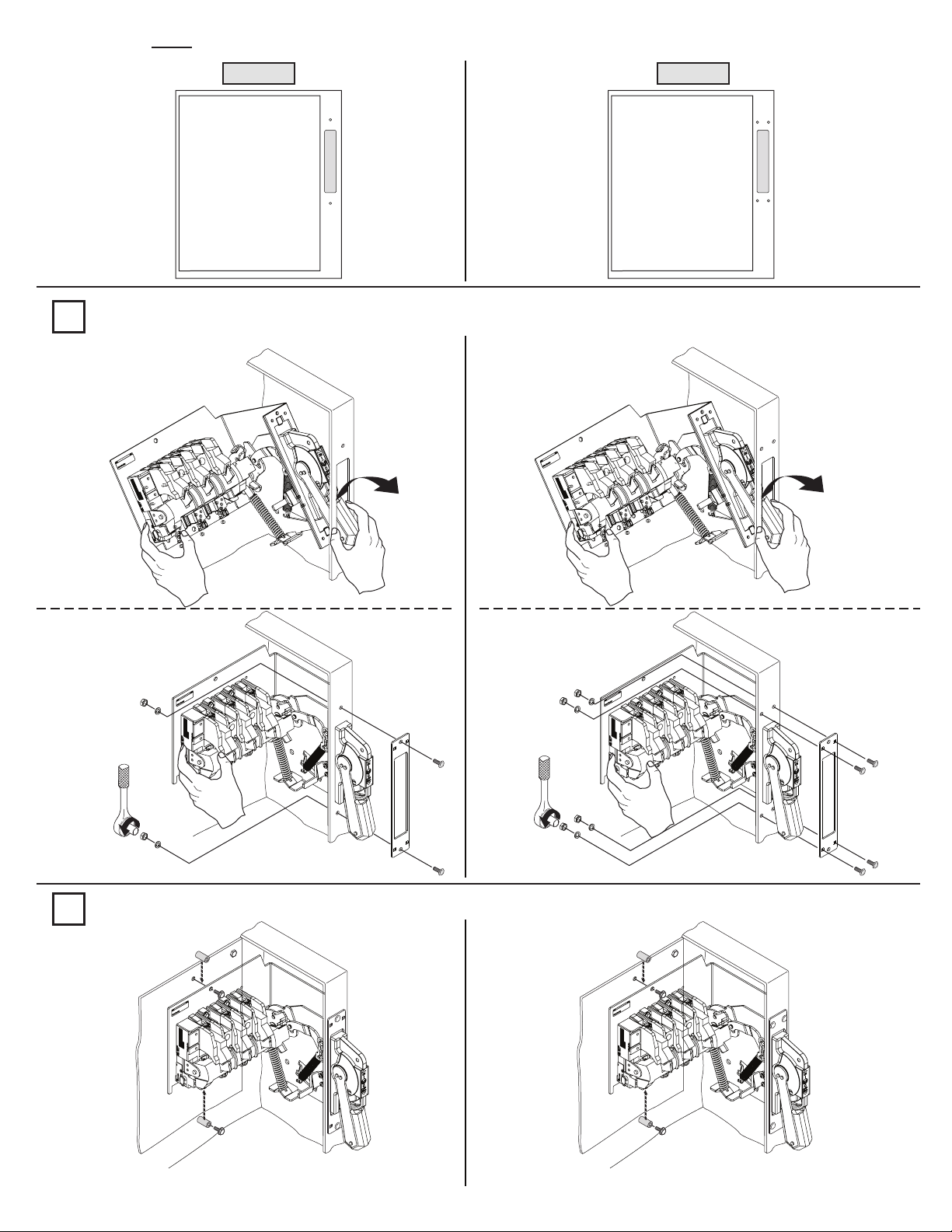
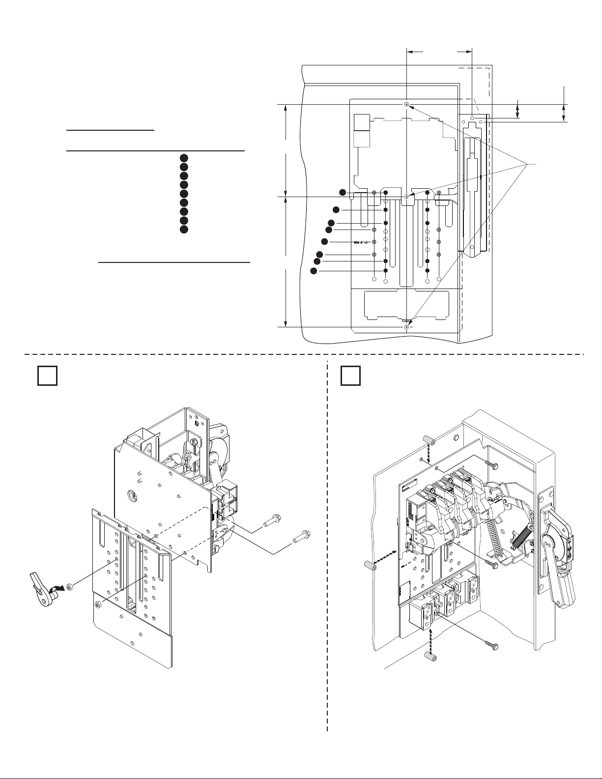
Enclosure with Pre-Drilled Handle Cutout
Option 1
Install Disconnect Switch (Left-hand installation unavailable.)
1
Option 2
35-45 lb-in
Install Disconnect Switch Standoffs
2
Standoffs & Bolts to be
Provided by User or
Enclosure Manufacturer
42052-195-01
DIR 10000075001 (Version 00)
23-37 lb-in
Standoffs & Bolts to be
Provided by User or
Enclosure Manufacturer
(2)
Page 3
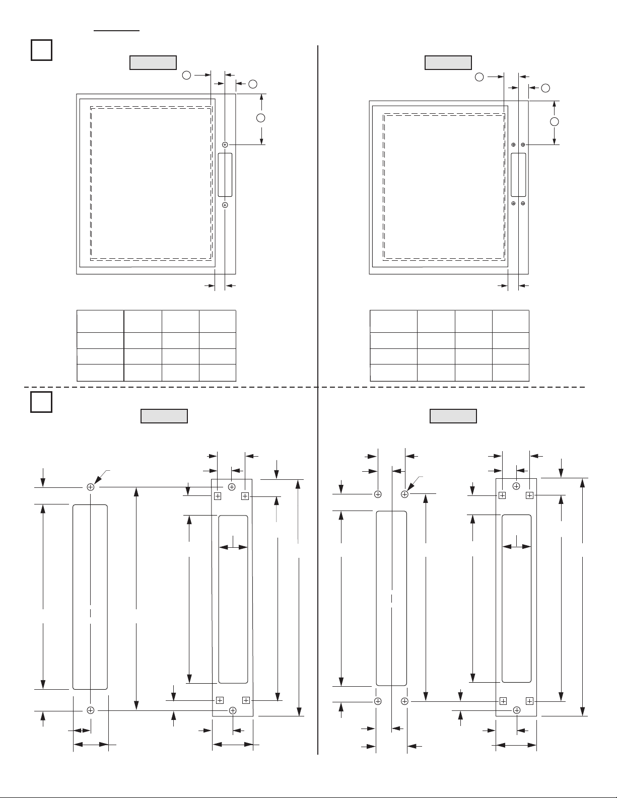
Enclosure without Pre-Drilled Handle Cutout
Locate Handle
1
Option 1
C
B
Option 2
F
E
NEMA
SIZE
30A, 60A
100A
200A
Drill Handle Holes
2
ENCLOSURE FLANGE
HANDLE CUT-OUT
15/32”
A
(min)
2-3/4"
4-1/4"
8-1/4"
Option 1
(2) .265” Dia.
Holes
B
(min)
1 - 3/16"
1 - 3/16"
1 - 3/16"
9/16”
13/16”
5/8” Min.
C
(min)
1 - 1/16"
1 - 1/16"
1 - 1/16"
FLANGE MOUNTED
COVER PLATE
1 - 1/8”
A
D
5/8” Min.
Enclosure Flange Cut-Out Dimensions (Option 2)Enclosure Flange Cut-Out Dimensions (Option 1)
NEMA
SIZE
30A, 60A
100A
200A
D
(min.)
3
4-1/2"
8-1/2"
E
(min.)
1 - 3/16"
1 - 3/16"
1 - 3/16"
F
(min.)
1 - 1/16"
1 - 1/16"
1 - 1/16"
Option 2
FLANGE MOUNTED
COVER PLATE
1 - 1/8”
9/16”
9/16”
13/16”
9/16”
ENCLOSURE FLANGE
HANDLE CUT-OUT
1-1/8”
9/16”
13/32”
(4) .203” Dia.
Holes
7 - 3/16”
27/32”
21/32”
8 - 1/2”
1 - 5/16”
42052-195-01
DIR 10000075001 (Version 00)
1/4”
6-3/8”
25/32”
1 - 3/16”
8”
1 - 9/16”
9-1/8”
(3)
7-3/16”
13/32”
21/32”
1-5/16”
1 - 3/16”
8”
6-3/8”
1/4”
25/32”
1 - 9/16”
8”
9-1/8”
Page 4
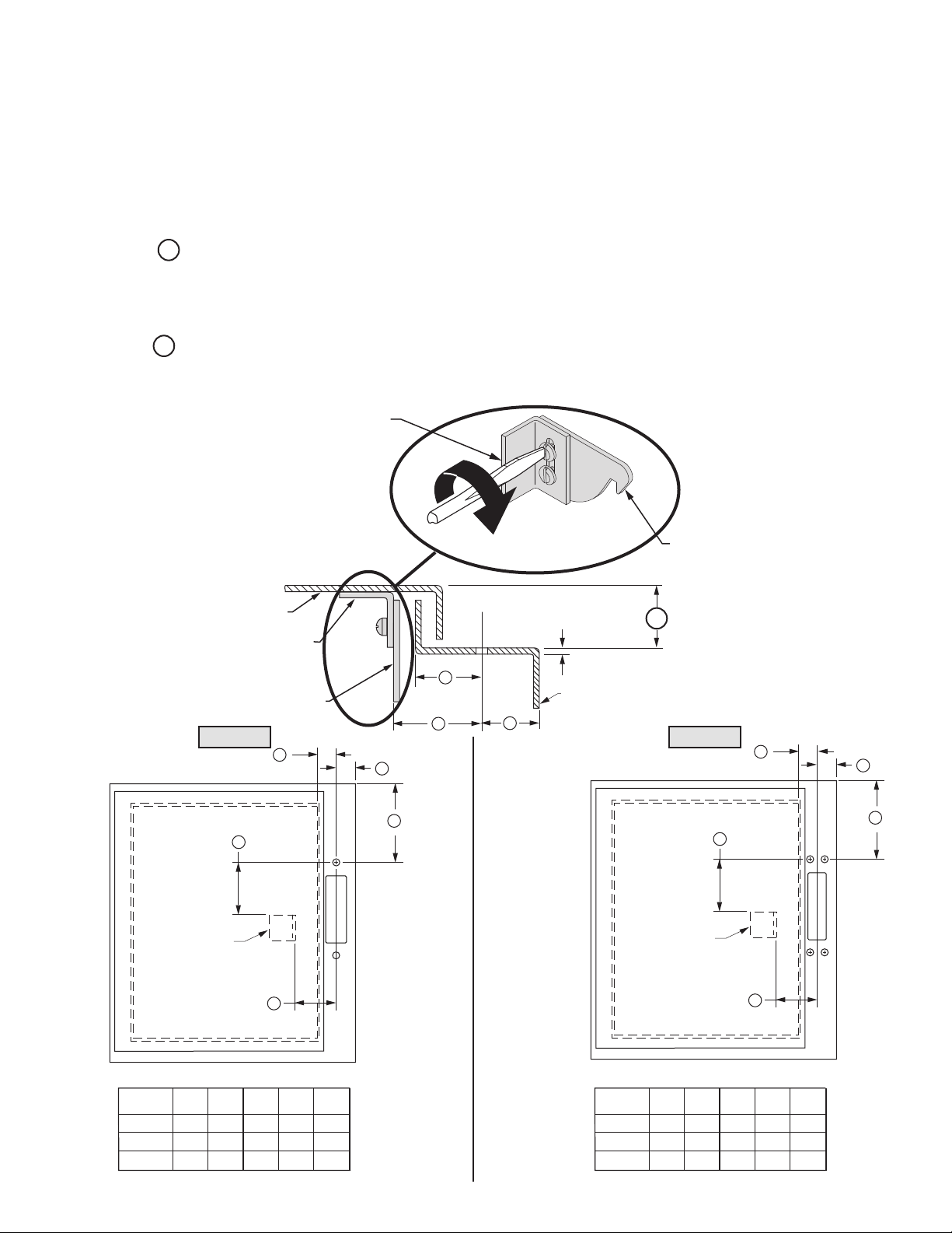
Enclosure Requiring Door Catch Bracket
Right-hand installation shown with or without enclosure door vault hardware
(Left-hand installation unavailable)
Door Catch Mounting Bracket:
L Provided with projections for welding.
L Projections can also be used as a guide for drilling holes.
L Can be used as a template to drill corresponding holes in the enclosure door.
L User to supply the hardware for fastening the bracket.
L The bracket hardware must be inaccessible to unauthorized personnel.
L Fasteners must provide the degree of ingress protection for the environmental rating of the enclosure.
Dimension K (3/4" to 1")
L When installed in any size enclosure without door vault hardware, use door catch provided with disconnect switch kit.
L When installed in small and intermediates size enclosures (15 inches to 40 inches) using door vault hardware kits
(1494F-L1, 1494F-L2 and 1494F-L3), use door catch with pivot lever provided with disconnect switch kit. Discard the door catch
supplied with the door vault hardware kit.
Dimension K (1-1/8" to 1-3/8")
L When installed in large enclosure using door vault hardware kit (1494F-L4), use the door catch assembly with the pivot lever
included with the disconnect switch. Discard the door catch supplied with the door vault hardware kit.
Mounting Bracket
Enclosure Door
Door Catch
Mounting Bracket
Door Catch
Option 1
C
E
Door Catch
TOP VIEW
Top
Door Catch (used without door
vault hardware kits)
Flange
Thickness
C
K
Enclosure
Base
D
B
Option 2
H
B
A
K
G
F
Door Catch
Mounting
Bracket
Enclosure Dimensions
NEMA
SIZE
30A, 60A
100A
200A
42052-195-01
DIR 10000075001 (Version 00)
A
(min)
2 - 3/4"
4 - 1/4"
8 - 1/4"
B
(min)
1 - 3/16"
1 - 3/16"
1 - 3/16"
C
(max)
1 - 1/16"
1 - 1/16"
1 - 1/16"
Door Catch
Mounting
Bracket
H
(max)
1 - 1/16"
1 - 1/16"
1 - 1/16"
J
J
2 - 1/8"
2 - 1/8"
2 - 1/8"
K
3 - 9/16"
3 - 9/16"
3 - 9/16"
D
Enclosure Dimensions
D
2 - 1/8"
2 - 1/8"
2 - 1/8"
E
3 - 13/16"
3 - 13/16"
3 - 13/16"
NEMA
SIZE
30A, 60A
100A
200A
F
(min)
3"
4 - 1/2"
8 - 1/2"
G
(min)
1 - 3/16"
1 - 3/16"
1 - 3/16"
(4)
Page 5
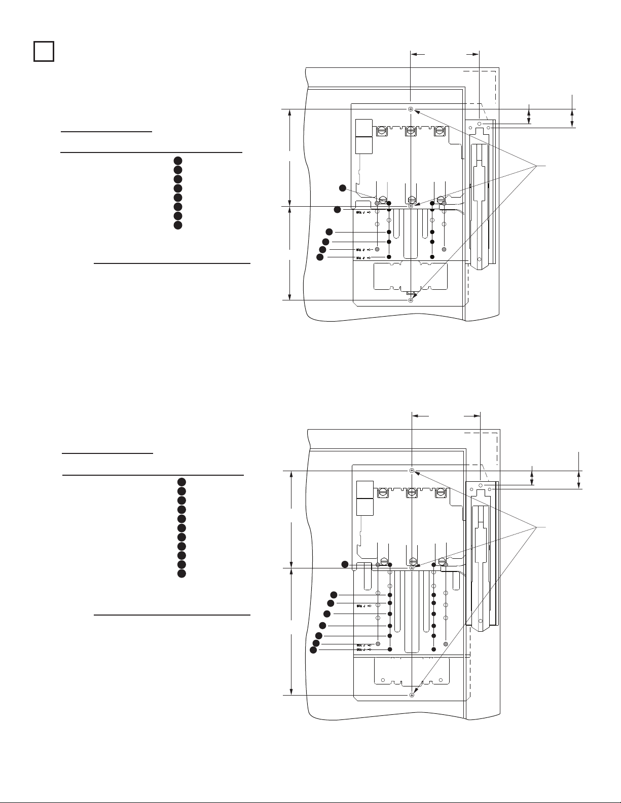
Fuse Block Adapter Plate Installation (Switch Rating 30A - 60A - 100A)
30 Amp Fuse Block Adapter Plate Kit (1494F-F30)
1
Fuse
Amps
30
30
30
30
60
60
60
60
Voltage Class
250
600
600
600
250
600
600
600
H/R
H/R
HRCII-C
H/R
H/R
HRCII-C
Position D
J
J
6
2
6
3
4
1
5
3
2 - 13/16”
5 - 5/8”
2 - 13/16”
4
-
3/16”
3 - 5/8”
6 - 1/8”
3”
4 - 3/16”
Hardware Torque (lb-in)
30
60
Fuse Block
Adapter Kit
Fuse
Clip
Lug to
Terminal
into Lug
40-60 22-37 20-25 20-25
Wire
Fuse
Amps
6”
4 - 5/16”
1 - 3/16”
15/16”
(Option 2)
(Option 1)
(3) - 9/32 Dia.
1
2
3
4
D
5
6
60 Amp Fuse Block Adapter Plate Kit (1494F-F60)
Fuse
Amps Voltage Class Position
30
30
30
30
60
60
60
60
100
100
100
250
600
600
600
250
600
600
600
250
600
600
H/R
H/R
J
HRCII-C
H/R
H/R
J
HRCII-C
H/R
J
H/R
8
3
8
5
6
2
7
5
2
4
1
Hardware Torque (lb-in)
30
60
100
Fuse Block
Adapter Kit
Fuse
Clip
Terminal
40-60 22-37 40-60 45-50
40-60 16-22 40-60 45-50
Fuse
Amps
Lug to
D
2 - 13/16”
5 - 5/8”
2 - 13/16”
4 - 3/16”
3
-
5/8”
6
-
1/8”
3”
4 - 3/16”
6 - 1/8”
4 - 15/16”
8 - 1/8”
Wire
into Lug
6”
4
-
5/16”
1
-
3/16”
15/16”
(Option 2)
(Option 1)
(3) - 9/32 Dia.
1
2
3
4
D
5
6
7
8
42052-195-01
DIR 10000075001 (Version 00)
(5)
Page 6
Fuse Block Adapter Plate Installation (Switch Rating 30A - 60A - 100A) - (Cont’d)
a
100 Amp Fuse Block Adapter Plate Kit (1494F-F100)
100 Amp Trailer Fuse Block (1494F-F100)
Fuse
Amps Voltage Class
60
60
60
60
100
100
100
100
200
Fuse
Amps
100
200
60
250
600
600
600
250
600
600
600
600
Fuse Block
Adapter Kit
H/R
J
H/R
HRCII-C
H/R
H/R
J
HRCII-C
J
Hardware Torque (lb-in)
40-60 22-37 90-110 150-165
40-60 16-22 90-110 150-165
Fuse
Clip
7
8
3
6
3
1
5
2
4
Lug to
Terminal
DPosition
4 - 3/16”
3 - 9/16”
6 - 11/16”
4 - 11/16”
6 - 11/16”
8 - 11/16”
5
-
1/2”
7 - 9/16”
6
-
1/4”
Wire
into Lug
6”
D
4 - 5/16”
1
-
3/16”
15/16”
(Option 2)
(Option 1)
(3) - 9/32 Di
1
2
3
4
5
6
7
8
2 3
40 - 60 lb-in
Standoffs & Bolts to be
Provided by User or
Enclosure Manufacturer
42052-195-01
DIR 10000075001 (Version 00)
(6)
Page 7

Fuse Block Adapter Plate Installation (Switch Rating 200A)
200 Amp Fuse Block Adapter Plate Kit (1494F-F200)
1
200 Amp Trailer Fuse Block (1494F-F200)
Fuse
Amps Voltage Class
100
100
100
100
200
200
200
200
400
Fuse
Amps
100
200
400
250
600
600
600
HRCII-C
250
600
600
600
HRCII-C
600
Fuse Block
Adapter Kit
40-60 16-22 160-190 275-305
40-60 16-22 160-190 275-305
Position
Fuse
Clip
5
2
7
7
3
1
6
6
4
Terminal
Lug to
5 - 7/8”
7 - 7/8”
4 - 5/8”
4
6 - 3/4”
9 - 1/4”
5 - 3/8”
5 - 3/8”
6
-
H/R
H/R
J
H/R
H/R
J
J
Hardware Torque (lb-in)
D
5/8”
1/4”
into Lug
Wire
8 - 3/16”
D
1
2
3
4
5
6
7
400A J
200A J
100A J
4 - 23/32”
1 - 3/16”
(Option 2)
15/16”
(Option 1)
(3) - 9/32 Dia.
2
40 - 60 lb-in
3
Standoffs & Bolts to be
Provided by User or
Enclosure Manufacturer
42052-195-01
DIR 10000075001 (Version 00)
(7)
Page 8

Phase Barrier Replacement Kit (Switch Rating 30A - 60A)
1494F-PH2
1 2
1
2
Disconnect Switch
Phase Barrier
Part No. 40392-097
30 Amp Disconnect Switch and Fuse Block Shown
Fuse Block
Phase Barrier
Part No.
40392-098
Fuse Clip Installation (Switch Rating 30A - 60A)
1
23 - 37 lb-in
2
2
CLICK
1
CLICK
2
Class R
Fuses Shown
42052-195-01
DIR 10000075001 (Version 00)
Class R
Fuse Clips
Shown
1
30 Amp Disconnect Switch and Fuse Block Shown
(8)
Page 9

Phase Barrier Replacement Kit (Switch Rating 100A)
R
1494F-PH3
Switch Phase Barrier
Trailer Block Phase Barrier
1
2
CLICK
Fuse Clip Size and Class
60 A
100 A
200 A
200 A
600V H - R
600V H - R
600V H - R
250V H - R
2
2
Fuse Clip Size and Class
60 A
1
60 A
100 A
100 A
250V H - R
600V J
250V H - R
600V J
600V J200 A
1
CLICK
3
1
2
Fuse Clip Installation (Switch Rating 100 Amp)
1
16 - 22 lb-in
2
2
CLICK
1
1
CLICK
2
100 Amp Class
Fuses Shown
2
23 - 37 lb-in
42052-195-01
DIR 10000075001 (Version 00)
1
(9)
Page 10

Phase Barrier Replacement Kit (Switch Rating 200A)
1494F-PH4
1
1
2
5
40 - 60 lb-in
3
2
CLICK
4
1
2
3
CLICK
42052-195-01
DIR 10000075001 (Version 00)
(10)
Page 11

Fuse Clip Installation (Switch Rating 200A)
1
16 - 22 lb-in
2
2
1
1
Fuse Clip Installation (Switch Rating 200A) for 400A Class J Fuses (Cat. No. 1401-N171)
23 - 37 lb-in
2
1
2
16 - 22 lb-in
2
150 - 200 lb-in
1
42052-195-01
DIR 10000075001 (Version 00)
(11)
Page 12

Dimensions
Spacers /
Standoffs
Provided by
User or
Enclosure
Manufacturer
H
(Min)
J Q
Non-Fusible Disconnect Switch
R
E
D
Fusible Disconnect Switch
A
B
1-1/8”
M
C
F
1/4”
K LG
(2) - 9/32 Dia.
Spacers /
Standoffs
Provided by
User or
Enclosure
Manufacturer
Switch
Size
H
(Min)
J
ABC EFGH
R
Q
E
D
See Fuse Block
Adapter Plate Section
See Fuse Block
Adapter Plate Section
(Min)
A
B
1-1/8”
N
P
JD
KMNPQRL
M
C
F
1/4”
K LG
(3) - 9/32 Dia.
30A
60A
100A
200A
9 - 3/16”
9
9
-
3/16”
-
-
9
3/16”
5/8”
4
-
5/16”
4
-
5/16”
-
5/16”
4
-
3/4”
4
42052-195-01
DIR 10000075001 (Version 00)
1
-
1/8”
1
-
1/8”
-
1/8”
1
-
5/32”
1
-
8
6”
6”
6”
3/16”
3/8”
3/8”
3/8”
1
1
1
-
-
-
9/16”
9/16”
9/16”
2”
10
10
10
10
-
-
-
-
29/32”
1/2”
1/2”
1/2”
8
8
9
9
-
-
-
-
1/2”
1/2”
3/4”
3/4”
6
-
7/8”
6-
7/8”
-
1/8”
8
-
1/8”7/16”
8
8”
8 - 1/2”
8”
8
8”
8
8
8”
15/16”
3 - 21/32”
15/16”
15/16”
3
3
-
1/2”
-
1/2”
-
1/2”
-
21/32”
-
21/32”
-
3
3/4”
7
7
7
7
-
5/16”
-
5/16”
-
5/16”
-
1/2”
5
3”
-
7/16”
3”
5
-
7/16”
3”
-
7/16”
5
-
3”1 - 5/16”
7/16”
5
(12)
Page 13

Installation--
)
Vault Hardware Latching (1494F-L1) - Top and Side Latching
(40 Inches Maximum Enclosure Height)
1
Latching rod may be supplied
by enclosure manufacturer
2
2
Drive-Lok Pin
1
(Optional screw
and nut included
with kit)
3 4
3
40 - 60 lb-in
Gasket to be installed inside door.
40 - 60 lb-in
1
Optional number of
1
150 - 200 lb-in
2
shims used (0 - 3).
More shims, more
gasket compression
23 - 37 lb-in
2
23 - 37 lb-in
3
23 - 37 lb-in
Assemble door catch
and defeater lever
actuator in center of
slots. (Parts included
with the disconnect
switch).
Adjustment may be
required (up or down
1
for interlocking to
work properly.
42052-195-01
DIR 10000075001 (Version 00)
(13)
Page 14

Installation--
c
f
Vault Hardware Latching (1494F-L2, -L3) -
(40 Inches Maximum Enclosure Height-1494F-L2)
(60 Inches Maximum Enclosure Height-1494F-L2, -L3)
Top and Bottom Latching or Top, Side and Bottom Latching
Vault Hardware Latching (1494F-L4 for Large Enclosures) -
(84 Inches Maximum Enclosure Height)
1
3
2
Latching rod may be
supplied by
enclosure manufacturer
1
Drive-Lok Pin
(Optional screw and
nut included with kit)
Top, Side and Bottom Latching
4
Drive-Lok Pin
(Optional screw and
nut included with kit)
2
3
4
3
40 - 60 lb-in
3
23 - 37 lb-in
Gasket to be
installed inside door.
Assemble door cat
and defeater lever
actuator in center o
slots. (Parts include
with the disconnect
switch).
Adjustment may be
required (up or dow
1
for interlocking to
work properly.
40 - 60 lb-in
1
1
3
40 - 60 lb-in
2
150 - 200 lb-in
23 - 37 lb-in
Optional number
of shims used
(0 - 3).
More shims,
more gasket
compression
2
23 - 37 lb-in
42052-195-01
DIR 10000075001 (Version 00)
(14)
Page 15

Installation-- Vault Hardware Latching (Non Pre-Drilled Enclosures)
2
Option 2Option 1
1 - 3/8”
1
-
1/8”
9/16”
(1494F-L1)
-
1/4”
3
G
(Min)
(1494F-L2,
1494F-L4)
H *
(Min)
C
(Min)
J *
(Min)
C + 1/16” *
(Min)
4 - 3/4”
Bracket
Guide
Bracket
2 - Holes
9/32” Dia.
3 - 1/4”
2 - 3/8”
13/16”
2 - Holes
13/32” Dia.
Guide
1 - 3/8”
B
1/4”
A
D
F
E
(Min)
1/4”
3/4” Dia.
B
M
Guide Bracket
Door Catch Bracket
(1494F-L1, 1494F-L2)
E + 3 - 1/2”
(1494F-L4)
-
3/8”
E + 3
N
Guide Bracket
M
3/4”
5/16”
N
3/4”
6 - Holes
+.000
.193” Dia.
-.003
3/8”
K
L
1/2”
2 - Holes
#10-32
5/16”
3/8”
(1494F-L1, 1494F-L
G minus 3/4”
(1494F-L4)
-
G minus 1
1/8”
(1494-L2)
H minus 3/4”
(1494-L4)
H minus 1 - 1/8”
* Non applicable for 1494F-L1
Vault Hardware
Kits
Switch
Size
AB C
(Min)
E
(Min)
FG
(Min)H(Min)
J
(Min)
KLD
M
N
Small and Intermediate Enclosures
4
-
1/2”
1494F-L1 *
1494F-L2 *
1494F-L3 *
30A
60A
100A
200A
3
-
3
-
-
3
-
3
7/8”
7/8”
7/8”
7/8”
3/8”
3/8”
3/8”
3/8”
3
-
1/16”
-
1/8”
2
3
-
1/16”
2 - 1/8”
-
1/16”
3
-
3
1/16”
-
1/8”
2
2
-
1/8”
3
-
13/16”
-
1/2”
4
3
-
13/16”
-
1/2”
4
4
-
1/2”
-
3
-
3
13/16”
13/16”
18
23 - 25/32”
13”
14”
-
7/8”
8
-
1/8”
8
-
1/8”
-
1/8”
8
-
1/8”
8
5”
1/2”
5”
1/2”
5”
1/2”
5”
1/2”
1/4”
1/4”
1/4”
1/4”
11/16”
11/16”
11/16”
11/16”
1/2”
1/2”
1/2”
1/2”
Large Enclosures
5”
3
-
13/16”
13 - 1/8”
5”
3
-
5”
-
3
5”
-
3
13/16”
13/16”
13/16”
13
18
23 - 13/32”
-
13/16”
9
9
-
5/8”
-
13/16”
-
1/2”
-
13/16”
9
-
13/16”
9
6”
6”
6”
6”
5/8”
5/8”
5/8”
5/8”
5/16”
5/16”
5/16”
5/16”
1-1/4”
1-1/4”
1-1/4”
1-1/4”
3/4”
3/4”
3/4”
3/4”
1494F-L4 *
30A
60A
100A
200A
1/2”
4”
4”
4”
4”
1/2”
1/2”
1/2”
3 - 3/4”
3
-
3/4”
-
3/4”
3
-
3/4”
3
2
-
1/8”
2
-
1/8”
-
1/8”
2
-
1/8”
2
* When using 1494F-L1, -L2, -L4 vault hardware kits with Series A 1494F-N30, 1494F-NF30, 1494F-N60, 1494F-NF60, 1494F-N100, 1494F-NF100, 1494D-N4,
1494D-N5, 1494M-N30, 1494M-NF30, 1494M-N60, 1494M-NF60, 1494M-N100 or 1494M-NF100 it may be necessary to order adapter 1494F-N13. (Required for
Hoffman A22 Series B or later enclosures.)
42052-195-01
DIR 10000075001 (Version 00)
(15)
Page 16

Testing Vault Hardware Latching and Enclosure Seal
Close door against enclosure base. The door handle should
1 2
be in the 6 o’clock position in line with the length of the door
when fully latched and the enclosure is sealed.
Turn release screw counterclockwise and hold screw in that
position to release initial catch from beneath enclosure flange.
Handle should rotate clockwise to approximately the 9 o’clock
3 4
position under spring action. The locking bars should have
retracted from top and bottom of door and center latch cleared
right hand flange.
Reclose door against enclosure base. Turn door handle
counterclockwise to the 6 o’clock position. You should
hear two distinct clicks as you turn the handle.
Handle should remain in this position.
“Click”
“Click”
42052-195-01
DIR 10000075001 (Version 00)
(16)
Page 17

Testing Vault Hardware Latching and Enclosure Seal (Cont’d)
Return to Step 3 to open door. Close the
5 6
door on the base and turn the handle to
the 6 o’clock position. Door should be
sealed securely to the enclosure base.
Close the door and turn the door handle counterclockwise until the first “click”
is heard. Move the disconnect handle to the ON position (do not force). If the
disconnect handle can be moved, the defeater lever actuator is properly adjusted.
Continue rotating door handle to fully closed position (6’oclock).
“Click”
Move defeater lever actuator upward
to allow disconnect handle to be turned
to on position later.
Move door catch downward to allow
operation of handle relative to door
latching handle sooner.
42052-195-01
DIR 10000075001 (Version 00)
(17)
Page 18

Bulletin 1494F Disconnect Switch Kit
Disconnect Kit
Disconnect Switch and Handle
with Mechanism
Fuse Block
with Adapter Plate
Cat No.
Switch and Handle with Right Hand Mechanism
(Non-Fusible and Fusible)
1494F-N30 (30A)
1494F-N60 (60A)
1494F-N100 (100A)
1494F-N200 (200A)
1494F-F30 (30A)
1494F-F60 (60A)
1494F-F100 (100A)
1494F-F200 (200A)
42052-195-01
DIR 10000075001 (Version 00)
Fuse Clips
1401-N41 (Class H, 30A - 250V)
1401-N42 (Class H,J, 30A - 600V,
Class H, 60A-250V)
1401-N43 (Class H,J, 60A - 600V)
1401-N44 (Class H,J, 100A-250V, 100A-600V)
1401-N45 (Class H,J, 200A-250V, 200A-600V)
1401-N50 (Class R, 30A - 250V)
1401-N51 (Class R, 30A - 600V, 60A-250V)
1401-N52 (Class R, 60A - 600V)
1401-N53 (Class R, 100A - 250V, 100A-600V)
1401-N54 (Class R, 200A-250V, 200A-600V)
1401-N171 (Class J, 400A-250V / 600V)
(18)
Page 19

Bulletin 1494F Disconnect Switch Optional Accessory List
Optional Accessories
(Installation Instructions
Included with Accessory Kits)
Electrical
Interlock
Terminal
Adapter Kit
Use with Switch with Right Hand Mechanism
1495-N34 (1-N.O./N.C.) (30A - 60A - 100A)
1495-N35 (2-N.O./N.C.) (30A - 60A - 100A)
1495-N43 (1-N.O./N.C.) (200A)
1495-N44 (2-N.O./N.C.) (200A)
1494R-N16 (30A)
1494R-N17 (60A)
1494R-N18 (100A)
1494R-N19 (200A)
Cat No.
Line Side
Cover
Auxiliary
Contact
Lug
Connectors
Phase
Barrier
Fuse
Cover
with Door
1495-N80 (30A - 60A - 100A)
1495-N81 (200A)
1495-N8 (1-N.O.) (30A - 60A - 100A - 200A)
1495-N9 (1-N.C.) (30A - 60A - 100A - 200A)
Low Energy
1495-N8X (1-N.O.) (30A - 60A - 100A - 200A)
1495-N9X (1-N.C.) (30A - 60A - 100A - 200A)
(Saddle Clamps Included)
(CU Wire Size #14 . . #8 AWG) (30A)
1494R-N1
(CU Wire Size #14 . . #4 AWG) (60A)
1494R-N2
(CU Wire Size #8 . . #1/0 AWG) (100A)
1494R-N3
(CU Wire Size #6 . . #4/0 AWG) (200A)
1494F-PH2 (30A - 60A)
1494F-PH3 (100A)
1494F-PH4 (200A)
Switch
Rating
30A
30A
60A
30A
60A
60A
100A
30A
60A
100A
100A
200A
Fuse
Class
Non-Fusible
H, R
H, R
J
J
Non-Fusible
Non-Fusible
H, R
H, R
J
H, R
J
Non-Fusible
H, J, R
J
Fuse Clip
Rating
250V 600V
----
----
30A
----
60A
----
30A
30A
60A
60A
----
----
----
----
----
30A
----
60A
100A
100A
100A
100A
200A
200A
----
----
200A
200A
400A
400A
Cat No.
1495-N64
1495-N65
1495-N66
1495-N67
42052-195-01
DIR 10000075001 (Version 00)
(19)
Page 20

42052-195-01
DIR 10000075001 (Version 00)
Print in U.S.A.
 Loading...