

Page 1

MANUAL
May be covered by one or more of the following: U.S. Patents
#4538297, 4647876, 4696044, 4745309, 4881047, 4893099, 5124657, 5263091,
5268527, 5319713, 5333201, 5402498 and 5493617.
Other patents pending. Foreign patents pending.
1
Page 2

Your PatchMate LOOP 8 Floor has been designed to comply with the following Standards and Directives as set forth
by the European Union:
Council Directive(s): 89/336/EEC, 73/23/EEC, 76/769/EC, 1994/62/EC, 2000/
53/EC, 2002/95/EC
Standard(s): EN55022, EN50082-1, EN60065
This means that this product has been designed to meet stringent guidelines on how much RF energy it can emit,
and that it should be immune from other sources of interference when properly used. Improper use of this equipment
could result in increased RF emissions, which may or may not interfere with other electronic products.
To insure against this possibility, always use good shielded cables for all audio input and output connections. This will
help insure compliance with the Directive(s).
SPECIFICATIONS
Active Input Impedance
Active Output Impedance
Input Jacks
Send Jacks
Return Jacks
Output Jacks
Power requirements
Dimensions
MIDI In/Thru/Out
Phantom power
Presets
MIDI program change
1.5M ohms
150 ohms
1/4” mono
1/4” mono
1/4” mono
1/4” mono
9VAC 2 amps 4 pin DIN connector
19” wide, 3” tall, 4.5" deep
483mm x 75mm x 114mm
7 pin DIN, (standard 5 pin cable plugs in without phantom power feature)
Thru/Out 5 pin DIN
Provided on MIDI IN jack pins 6 and 7 - 9VAC 2 amps
128
0-127
Midi control
Change commands in groups of 8 with 16 banks 0-7, 8-15, 16-
23.................120-127
Relays
Copyright © 2009 GHS Corporation.
All rights reserved.
2
Gas lled, contacts gold plated
Page 3

PRECAUTIONS
NOTE: IT IS VERY IMPORTANT THAT YOU READ THIS SECTION TO PROVIDE YEARS OF TROUBLE FREE USE. THIS UNIT REQUIRES CAREFUL HANDLING.
• All warnings on this equipment and in the operating instructions should be
adhered to and all operating instructions should be followed.
• Do not use this equipment near water. Care should be taken so that objects
do not fall and liquids are not spilled into the unit through any openings.
• The power cord/adapter should be unplugged from the outlet when left
unused for a long period of time.
• Do not block any ventilation openings (if applicable). Install in accordance with the manufacturer’s instructions.
• Do not install near any heat sources such as radiators, heat registers, stoves
or other apparatus (including ampliers) that produce heat.
• Only used attachments/accessories specied by the manufacturer.
• Do not use this product with any case, stand, tripod, bracket or table that
is not specied by the manufacturer. Insure that the case, stand, tripod,
bracket etc. is properly adjusted and setup (follow all instructions). Extra
care and caution should be taken to avoid tip over and injury.
• Unplug this apparatus during lightning storms or when unused during long
periods of time.
Refer all service to qualied service personnel. Servicing is required when the apparatus has been
damaged in any way, such as power supply or plug is damaged, liquid has been spilled or objects have
fallen into the apparatus or if the apparatus has been exposed to rain or moisture, does not operate normally or has been dropped.
DO NOT ATTEMPT TO SERVICE THIS EQUIPMENT. THIS EQUIPMENT
SHOULD BE SERVICED BY QUALIFIED PERSONNEL ONLY. DO NOT MAKE
ANY INTERNAL ADJUSTMENTS OR ADDITIONS TO THIS EQUIPMENT AT
ANY TIME. DO NOT TAMPER WITH INTERNAL ELECTRONIC COMPONENTS
AT ANY TIME. FAILURE TO FOLLOW THESE INSTRUCTIONS MAY VOID THE
WARRANTY OF THIS EQUIPMENT, AS WELL AS CAUSING SHOCK HAZARD.
OPERATING TEMPERATURE
Do not expose this unit to excessive heat. This unit is designed to operate between
32° F and 104° F (0° C and 40° C). This unit may not function properly under extreme
temperatures.
3
Page 4

Introduction
The PatchMate LOOP 8 Floor provides 8 discrete Loops all with True Bypass, buffered and non buffered signal paths, 128 programmable presets with Real time control using the 9 high quality metal foot
switches.
The eight LOOPs may be congured for multiple purposes including Channel switching, effects loops,
guitar routing and more. Add preset programmability along with pedal True Bypass to any standard
pedal board with ease!
The PatchMate LOOP 8 Floor is easy to set up and program with real time user controls. Program
the unit from the top panel using the switches. Recall the rst 8 user presets using the 8 onboard
footswitches or access a total of 128 presets using external MIDI program changes. External MIDI Continuous Controllers add the ability to trigger loops externally.
The PatchMate LOOP 8 Floor supports intelligent latching and momentary switch sensing, which allows
the user to use any MIDI Continuous Controller number without any other programming effort!
The PatchMate LOOP 8 Floor has buffered ACTIVE and PASSIVE inputs, with PASSIVE/ACTIVE and
ACTIVE outputs on the back. It may also be set to any MIDI channel and is programmable from the top
panel as well as congured for use on any of 16 banks of controllers via the top panel switches.
MIDI In/Out/Thru is also provided making it the ideal addition to any oor setup that can benet from
the exibility attained with Programmable Presets, 8 LOOPS with True Bypass, Real Time and External
Loop Control capabilities. Additionally, using Rocktron’s SMART CONTROLLER TECHNOLOGY,
the PatchMate LOOP 8 Floor can also be used for momentary amplier switching!
For further expansion Rocktron recommends combining the PatchMate Loop 8 Floor with any Rocktron
MIDI controller, including the MIDI XChange, MIDI Mate, All Access and All Access LTD.
Enjoy!
4
Page 5
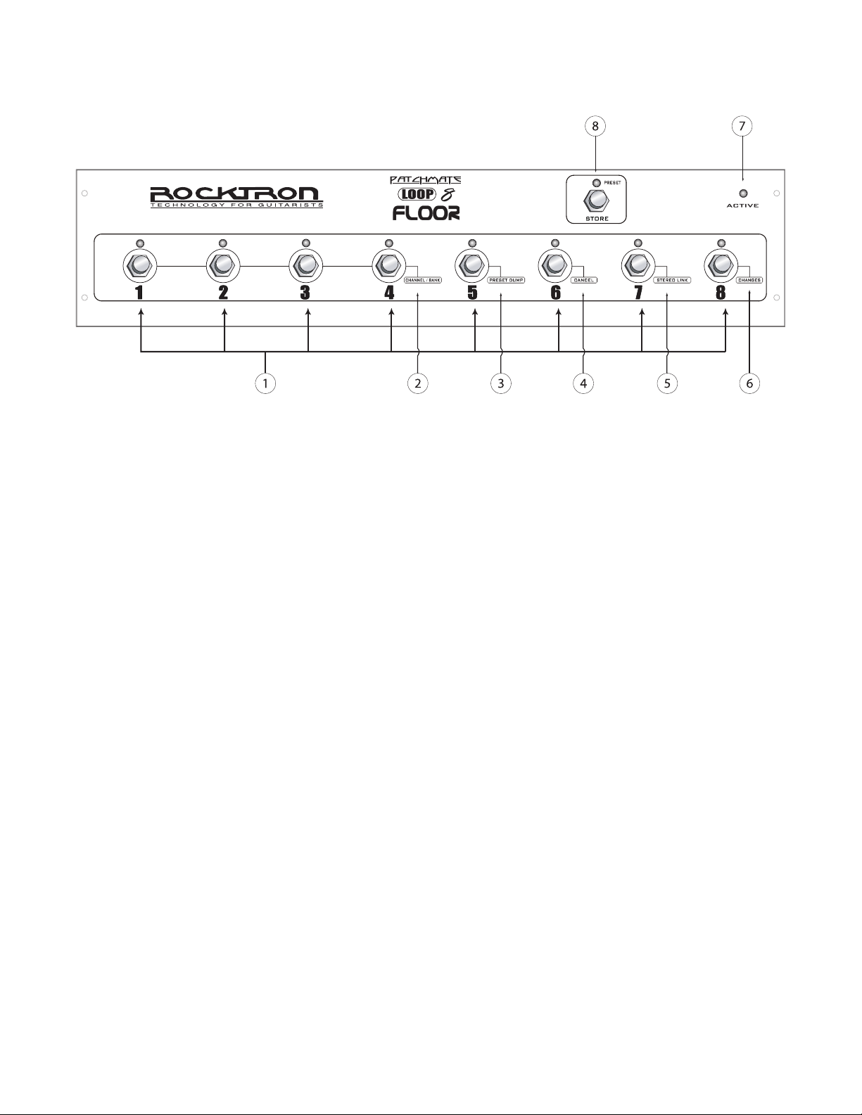
PatchMate LOOP 8 Floor Top Panel
1 LOOP Switches
These switches are used to turn "on/off" each individual loop. The LED above each switch will
display the "current" status of the PatchMate. If an LED above a switch is lit, that LOOP is active. If the LED above a switch is not lit, the LOOP is not active or off.
SECONDARY SWITCH FUNCTIONS - DESCRIPTIONS 1-6
These functions are only available once you have entered the "SETUP MODE". To enter the SETUP
MODE, turn the power "ON" - you now have 3 seconds to press the STORE SWITCH once. After the 3
second time out it will enter the SETUP MODE...... and the STORE LED will "blink".
2 CHANNEL/BANK Function
In this function switches 1, 2, 3 and 4 are used to select the MIDI Channel and MIDI Control-
lers Banks. See the section titled "SETUP YOUR PATCHMATE LOOP 8 FLOOR" later in this
manual for the procedure.
3 PRESET DUMP Function
In this function switch 5 is used to dump presets from one PatchMate LOOP 8 Floor to another
PatchMate LOOP 8 Floor. See the section titled "PRESET DUMP" later in this manual for the
proceedure.
4 CANCEL Function
In this function switch 6 is used to CANCEL any secondary function changes that you have
made before you have stored them.
5 STEREO LINK Function
In this function switch 7 is used to select the STEREO LINK function whic allows you to link
LOOPs within the PatchMate Loop 8 Floor for Stereo control. See the section titled "STEREO
LINK" later in this manual for the procedure.
5
Page 6

PatchMate LOOP 8 Floor Top Panel Continued......
6 CHANGES Function
In this function switch 8 is used to select if you would like the PatchMate LOOP 8 Floor to
respond to MIDI Program changes and MIDI Controller changes or not. See the section in this
manual called "CHANGES Function" for more details.
7 ACTIVE - Power LED
When this LED is lit the PatchMate LOOP 8 Floor is "ON" or "ACTIVE". To turn on the
PatchMate LOOP 8 Floor, use the POWER switch located on the back panel. See PatchMate
LOOP 8 Floor Back Panel section of this manual for more information on the power switch.
8 STORE Button & PRESET LED
This Switch is used to STORE (save) any preset that has been changed and to put the PatchMate
LOOP 8 Floor into "PRESET" mode.
See "STORING PRESETS" and "PRESET MODE" sections in this manual for more details on
these functions.
6
Page 7
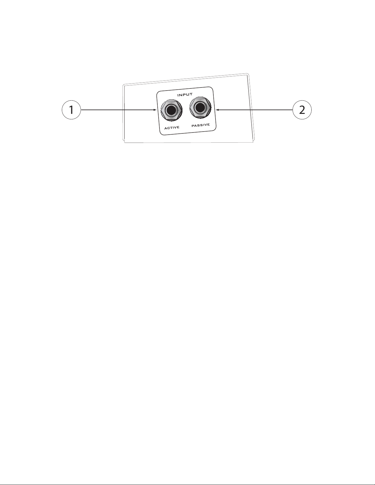
PatchMate LOOP 8 Floor Top Panel Side Panel
1 ACTIVE Input Jack
Plug your guitar into this jack to use the buffered input. This ACTIVE Input Jack is connected
to an active buffer that helps maintain signal strength when driving multiple devices in parallel. This "buffered" output is present on the "ACTIVE OUTPUT" on the back panel of the
PatchMate.
ACTIVE INPUT (front panel) → BUFFER (internal) → ACTIVE OUTPUT (back panel)
Note: When the ACTIVE INPUT Jack is used, the buffered signal is present at the PAS.-
ACT. OUTPUT as well, allowing you to connect another device to this jack.
ACTIVE INPUT (front panel) → BUFFER (internal) → PAS.-ACT.. OUTPUT (back panel)
2 PASSIVE Input Jack
Plug your guitar into this jack if you would like to bypass the buffered input allowing your guitar
signal to "feed thru" wire to wire. This "feed thru" signal is present on the "PAS.-ACT. OUTPUT" on the back panel of the PatchMate
PASSIVE INPUT (front panel) → PAS.-ACT. OUTPUT (back panel)
Note: When the PASSIVE Input is NOT being used the ACTIVE (buffered) OUTPUT
will be present at the PAS.-ACT. OUTPUT. Thus, you can connect another device to
PAS.-ACT. OUTPUT and it will have the buffered signal.
ACTIVE INPUT (front panel) → BUFFER (internal) → PAS.-ACT.. OUTPUT (back panel)
7
Page 8
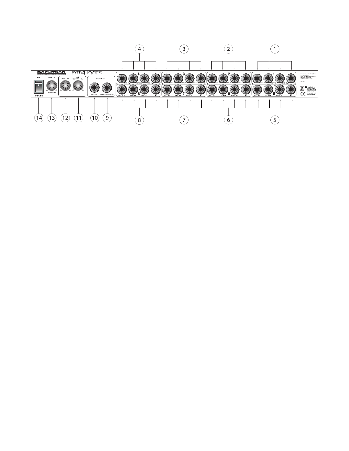
PatchMate LOOP 8 Floor Back Panel
NOTE: The following example is to illustrate a serial chain of effects and how the
Patchmate Loop 8 Floor may be applied. It is not necessary to daisy chain each
LOOP in the order listed below. You may use any LOOP you desire and in any
order you choose.
1 LOOP Section Number "1"
These jacks are used to connect your rst device in the signal chain. These jacks correspond to
the LOOP Button Number "1" on the front panel of the PatchMate LOOP 8 Floor.
2 LOOP Section Number "2"
These jacks are used to connect your second device in the signal chain. These jacks correspond
to the LOOP Button Number "2" on the front panel of the PatchMate LOOP 8 Floor.
3 LOOP Section Number "3"
These jacks are used to connect your third device in the signal chain. These jacks correspond to
the LOOP Button Number "3" on the front panel of the PatchMate LOOP 8 Floor.
4 LOOP Section Number "4"
These jacks are used to connect your fourth device in the signal chain. These jacks correspond to
the LOOP Button Number "4" on the front panel of the PatchMate LOOP 8 Floor.
5 LOOP Section Number "5"
These jacks are used to connect your fth device in the signal chain. These jacks correspond to
the LOOP Button Number "5" on the front panel of the PatchMate LOOP 8 Floor.
6 LOOP Section Number "6"
These jacks are used to connect your sixth device in the signal chain. These jacks correspond to
the LOOP Button Number "6" on the front panel of the PatchMate LOOP 8 Floor.
7 LOOP Section Number "7"
These jacks are used to connect your seventh device in the signal chain. These jacks correspond
to the LOOP Button Number "7" on the front panel of the PatchMate LOOP 8 Floor.
8 LOOP Section Number "8"
These jacks are used to connect your eighth device in the signal chain. These jacks correspond
to the LOOP Button Number "8" on the front panel of the PatchMate LOOP 8 Floor.
8
Page 9

PatchMate LOOP 8 Floor Back Panel...continued....
9 PASSIVE/ACTIVE OUTPUT Jack
Use this jack to plug into the next unit in your signal chain or the desired LOOP. This jack can
also be used as an output for the guitar signal when splitting the signal. This jack is the output
for the PASSIVE/ACTIVE input jack located on the side panel of the PatchMate LOOP 8 Floor.
10 ACTIVE OUTPUT Jack
This jack is used to send your guitar signal to your desired device, such as an amplier. This
jack is the output for the ACTIVE input jack located on the side panel of the PatchMate LOOP 8
Floor.
11 MIDI OUT/THRU Jack
Use this jack to plug into the rst MIDI controllable device in your signal chain.
12 MIDI IN Jack
Use this jack to plug in your MIDI controller. This jack is a 7 Pin MIDI Jack, however a stan-
dard 5 Pin MIDI Cable can be used. If plugging into a Rocktron MIDI controller such as the All
Access, MIDI Mate or MIDI Xchange, we recommend using the Rocktron RMM900 7-Pin MIDI
Cable (sold separately). Pins 6 and 7 supply phantom power to the Rocktron MIDI controller
when using the RMM900.
13 POWER Jack
Plug the included 9VAC adapter into this jack to provide power to the unit. Please follow all pre-
cautions as outlined in this manual and the manuals of the products that are being plugged into
the PatchMate LOOP 8 Floor. Failure to follow these precautions may void the warranty.
14 POWER Switch
Use this switch to power "on" or "off" the PatchMate LOOP 8 Floor. When on the "ACTIVE"
LED on the top panel will be lit.
9
Page 10
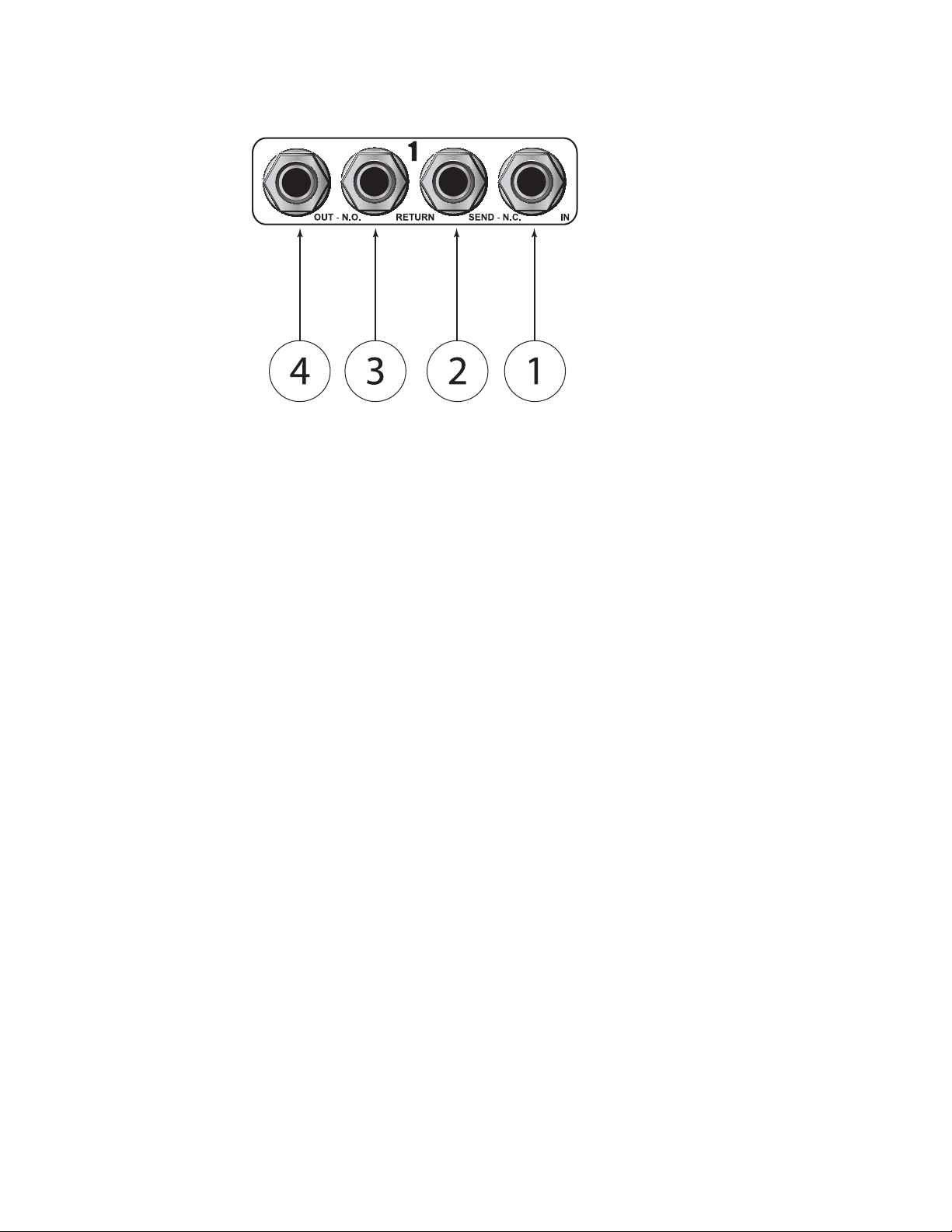
Individual LOOP Jacks Descriptions
1 IN Jack
This is the rst jack in the signal chain. The audio signal will enter the "LOOP" through this
jack.
2 SEND - N.C. Jack
This jack is used to send the signal to the desired audio device or to an ampliers footswitch jack
for N.C. (NORMALLY CLOSE) channel switching.
3 RETURN Jack
This jack is used to receive the returned signal from the desired audio device..
4 OUT - N.O. Jack
This jack is then used to send the signal to the next LOOP or next device in the signal chain or to
an ampliers footswitch jack for N.O. (NORMALLY OPEN) channel switching.
10
Page 11

Connections
Note: to simplify the connection diagrams, all of the jacks may not be shown in similar locations as on
unit, but the jack descriptions will show the correct connections
This connection diagram shows one way to use the LOOPs in the PatchMate LOOP 8 Floor to connect
stompboxes (pedals). Although only two connections are shown here, you can follow a similar progression of connections using LOOPs 3-8.
11
Page 12

Connections....continued.....
This connection diagram shows one way to use the LOOPs in the PatchMate LOOP 8 Floor. Although
only two connections are shown here, you can follow a similar progression of connections using LOOPs
3-8.
12
Page 13

Connections....continued.....
This connection diagram shows one way to use the LOOPs in the PatchMate to connect to multiple effects processors.
13
Page 14

1
OUT - N.O.
RETURN SEND - N.C. IN
To RETURN
of PatchMate
OUT to
next Loop
or device
IN to
Loop 1
PRE SET
PARAM ETER
ADJUS T
FUNC TION
SEL ECT
INPUT
LEVE L
PReamp 1
PRE SET
PARAM ETER
ADJUS T
FUNC TION
SEL ECT
INPUT
LEVE L
PReamp 2
Guitar
Signal
IN to
Preamp 1
IN to
Preamp 2
Out of
Preamp 1
Out of
Preamp 2
Connections....continued.....
This connection diagram shows one way to use the LOOPs in the PatchMate to connect to two different
preamps.
14
Page 15

Connections....continued.....
This connection diagram shows one way to use the LOOPs in the PatchMate to connect two ampliers
and select between the two.
15
Page 16

Connections....continued.....
This connection diagram shows one way to use the PatchMate LOOP 8 Floor's SENDS to change
change channels on an amplier.
16
Page 17

Connections....continued.....
This connection diagram shows one way to use the PatchMate LOOP 8 Floor's buffered connection.
17
Page 18

Connections....continued.....
This connection diagram shows one way to use the PatchMates buffered connection to connect to two
different preamps.
18
Page 19

Connections....continued.....
This connection diagram shows one way to connect the PatchMate to "MUTE" an effects processor
where parallel effect routings are being implemented.
19
Page 20

Connections....continued.....
This connection diagram shows how to connect the PatchMate to a MIDI Controller such as the
Rocktron MIDI Mate (use similar connections for the Rocktron All Access, All Access LTD and MIDI
Xchange.
Note: Internal PHANTOM POWER is provided by the PatchMate LOOP 8 Floor via the MIDI IN connector pins 6 & 7 and will power your Rocktron MIDI Controller eliminating the need to have a power
adapter plugged directly into the MIDI Controller.
The power provided is 9VAC. To use this feature you will need a Rocktron RMM900 MIDI Cable (sold
separately). See the Rocktron website - www.rocktron.com for more information.
20
The PHANTOM POWER feature is provided exclusive to support all ROCKTRON MIDI CONTROLLER products. Please refer to your owners manual before attempting to use this option with a MIDI
CONTROLLER other than a Rocktron product. Rocktron can not be held responsible for any damages
arising from improper use or connections.
Page 21

LOOPS and PRESETS Descriptions- Creating & Storing:
The PatchMate LOOP 8 Floor has two basic MODES of operation, LOOP MODE (Default) and PRESET MODE.
LOOP MODE
LOOP Mode is when the PatchMate is in a state where you can access (turn on/off) the individual
"loops" using the switches marked 1-8 .
In the PatchMate LOOP 8 Floor's LOOP mode (which is the default mode or state of the PatchMate
LOOP 8 Floor when the unit is turned ON) you can turn ON and/or OFF the various LOOPS using the
footswitches on the top panel. Switch 1 turns ON or OFF "LOOP 1" on the back panel, Switch 2 turns
ON of OFF "LOOP 2" on the back panel.
PRESET MODE
PRESET Mode is when the PatchMate is in a state where you can access (turn on/off) a "preset" using
the switches marked 1-8. You have a total of 8 PRESETS that can be accessed via the 8 Switches on the
PatchMate LOOP 8 Floor. To access more presets you will need to combine it with a Rocktron MIDI
Controller such as the Rocktron MIDI Xchange, MIDI Mate, All Access or All Access LTD.
A "PRESET" is a setup within the PatchMate LOOP 8 Floor where you may have multiple LOOPS set
to be on and/or off. Thus, instead of stepping on multiple switches to turn on and off loops, you can
select a predetermined set up (loops on or off) for a particular sound you like.
For example, if you have a LEAD sound that you like that requires loops 1, 2 and 7 to be
"on" and the other loops to "off" you can set up a PRESET that automatically tells the PatchMate Loop
8 Floor to turn "on" loops 1, 2 and 7 and turn "off" all other loops with one simple process, thus saving
you the effort of turning on and off each loop individually to get your LEAD sound.
When the PatchMate LOOP 8 Floor is rst turned on it is in "LOOP" mode. This means that you can
turn on/off the 8 individual loops using the switches marked 1 through 8. To enter into "PRESET"
mode, which allows you to select presets that you have stored.
To access the PRESET MODE press and release the STORE switch. The LED next to the word "PRESET" will light. You are now in "PRESET MODE" Thus, whatever switch you press next will be that
preset. NOTE, if for example you press switch number 1 you have accessed preset number 1, not LOOP
1. However, once you have pressed a switch the PatchMate LOOP 8 automatically reverts to LOOP
mode, so you may now turn ON/OFF LOOPs within that preset. To access a different preset, press and
release the STORE switch, the LED next to the word PRESET will light, now the next switch you press
it will select that particular PRESET.
21
Page 22

PRESETS - Selecting, Creating & Storing:
To create and store a preset follow these instructions;
To select a preset:
1 Press and Release the "STORE" Switch. The LED next to the word "PRESET" will light.
2 Press the desired PRESET number using the switches on the top panel. Switch Number 1 is
preset number 1 and so on.
3 After the preset has been selected the PatchMate LOOP 8 Floor will revert to "LOOP" Mode.
You will now be able to turn ON/OFF LOOPS within this preset.
To Create and Store a preset:
1 First you must determine which preset number you would like to create and then select that
number by pressing the corresponding switch. The preset number must be the rst switch you select in
this process.
2 Turn ON or OFF the desired LOOPS (including the loop corresponding to the switch you have
selected for the preset).
3 Press and HOLD the STORE switch down until the LED lights and then goes out.
You have now saved the preset.
Here is an example:
Lets set up SWITCH 1 (PRESET 1). In this preset we want LOOPs 2, 4 and 8 to be on all others off.
Thus the process is as follows:
1 Press and Release the "STORE" Switch. The LED next to the word "PRESET" will light.
2 Press switch 1 (this selects the preset number)
3 Press "ON" Loops 2, 4 and 8 by pressing switches 2, 4, and 8. The corresponding LEDs will be
"ON" or lit.
4 Turn "OFF" LOOPs 1, 3, 5, 6, and 7 by pressing switches 1, 3, 5, 6, and 7 if necessary. The
corresponding LEDS will be "OFF."
5 Press and HOLD the STORE switch until the RED LED lights (turns "ON") and continue to
hold until the LED turns "OFF." The preset now has been stored and the PatchMate LOOP 8 Floor has
reverted to "LOOP" Mode
22
So, lets test this to conrm. Turn "ON" all LOOPs. Now PRESS and RELEASE the STORE switch
quickly to access "PRESET" Mode. Press switch 1. If stored correctly LOOPS 2, 4 and 8 will be "ON"
and all other loops "OFF" indicated by the LEDs above switches 2, 4 and 8 being on and all other LEDs
off.
Page 23

PRESETS Recall - Loop and Instant
In order to provide the ultimate exibility the operating system has been upgraded.
The Patchmate Loop 8 Floor now has two different Preset Recall modes RETURN TO LOOP
and INSTANT. The Patchmate Loop 8 Floor is shipped in the RETURN TO LOOP Preset Recall .
Below are descriptions of each mode of operation. The following pages of this document replaces
pages 23 and 25 of the manual. You will nd details about how to perform the steps needed to
change the global setup conguration when INSTANT preset recall is desired.
PRESET RECALL MODES
RETURN TO LOOP :
1. Press the Store/Preset button to turn ON the Store/Preset led.
2. Press desired Preset button.
The Patchmate Loop 8 will recall the desired preset then automatically turn off the Store/Preset led and
return to Loop Access mode so you may have instant access to all of the loops.
INSTANT:
Press the Store/Preset button to turn ON the Store/Preset led. = Instant Preset Recall
You are now able to recall any of the 8 presets on the y with a single button access.
Note: When the preset is recalled the leds will reect the loops that are active within that preset.
Example: Preset 2 was previously programmed to have Loops 3, 5 and 8 ON.
When you press the preset 2 button the leds for Loops 3, 5 and 8 will light.
Press the Store/Preset button to turn OFF the Store/Preset led . = Instant Loop Access
Now you may access any of the Loops.
Tip:
The Patchmate Loop 8 oor has the ability to store and recall 128 presets when a Midi
Controller is used to send program changes to the Patchmate Loop 8 Floor.
To take full advantage this it is recommended to place the Patchmate Loop 8 Floor into the
RETURN TO LOOP preset mode in order to take advantage of instant access to any of the loops
via the Patchmate Loop 8 Floor's buttons while recalling presets with the use of an added Midi
Controller.
23
Page 24

Setup your PatchMate LOOP 8 Floor:
SETUP MODE:
To enter setup mode once you turn the power on you have 3 seconds to press the Store button once.
After the 3 second time out it will enter the SETUP MODE...... and the STORE LED will blink. You are
now in the MIDI CONFIGURATION PROGRAMMING MODE.
Note: If you do not press the store button within the rst 3 seconds proceeding the initial power up, the
Patchmate Loop 8 will automatically enter normal mode and recall preset number 1.
1. The LEDs above the switches on the top panel will be displaying the current MIDI CHANNEL conguration information. To modify the MIDI CHANNEL information press the desired button combination as shown on the MIDI CHANNEL SELECT diagram on the following page.
2. If you would like the PatchMate LOOP 8 Floor to respond to these program changes, press and release swtich 8. When the LED is "OFF" the PatchMate LOOP 8 Floor will respond to controller changes.
Once you have made your selections PRESS and RELEASE the STORE Switch. All relays and LEDs
will blink twice indicating store success. (Now proceed to step 3 under MIDI CONTROLLER SETUP)
*You may PRESS CANCEL (Switch 6 ) on the top panel then press the STORE switch and release if no
changes are needed.
MIDI CONFIGURATION PROGRAMMING (DEFAULT)
24
Page 25

MIDI Channel Select
25
Page 26

MIDI Controller Bank Setup
3. Once you have pressed the Store switch from step 2, the TOP PANEL SWITCH LEDs [ 1 thru 8 ] will
blink twice and the STORE BUTTON will continue to blink signifying that the MIDI CONTROLLER
BANK information is now being displayed.
4. You may now make your MIDI CONTROLLER BANK selections based on the MIDI CONTROLLER BANK SETUP diagram on the following pages or you may PRESS CANCEL [ 6 ] ON then
PRESS and RELEASE the STORE BUTTON.
5. If you would like the PatchMate LOOP 8 Floor to respond to these controller changes you just made,
press and release swtich 8. When the LED is "OFF" the PatchMate LOOP 8 Floor will respond to controller changes.
6. When you are ready to store the information simply PRESS and RELEASE the STORE SWITCH
(TWICE). The STORE LED will blink followed by the recall of preset 1.
Programming is now completed.
MIDI CONTROLLER PROGRAMMING (DEFAULT)
26
Page 27

MIDI Controller Bank Setup
*CANCEL:
PRESS SWITCH 6 then PRESS and RELEASE the STORE BUTTON to CANCEL the PROGRAMMING MODE.
Note: If CANCEL is executed any modied information will not be retained.
27
Page 28

Preset Dump
MIDI PRESET DUMP PROCEDURE:
To DUMP or copy presets from your PatchMate LOOP 8 Floor to another PatchMate LOOP 8 Floor,
rst connect the two via MIDI OUT of the sending PatchMate LOOP 8 Floor to the MIDI IN of the
receiving PatchMate LOOP 8 Floor.
1. Turn the PatchMate LOOP 8 Floor “ON”, within the rst 3 seconds press and release the STORE button. The Store Button will begin “ashing”. Note: this procedure must be done within 3 seconds of the
PatchMate LOOP 8 Floor being turned “ON If you forgot just turn the Patchmate Loop 8 off
for 5 seconds and try again.
2. Press SWITCH 5 (PRESET DUMP ), the LED above it will be lit.
3 PRESS and RELEASE the STORE BUTTON to execute a dump of all user preset data via MIDI. The
STORE BUTTON will blink rapidly during this process.
After the PatchMate LOOP 8 Floor has nished the Midi Preset Dump process the PROGRAMMING
MODE will be canceled and the PatchMate LOOP 8 Floor will return to the current PRESET.
28
Page 29

Stereo Link
To link loops in Stereo, follow these instructions
1. Turn the PatchMate LOOP 8 Floor "ON", then press and hold the STORE button down until the
STORE LED starts "ashing". Note that this procedure must be done within 3 seconds of the PatchMate
LOOP 8 Floor being turned "ON"
2. Press SWITCH 7 (STEREO LINK), the LED above it will be lit.
3 SWITCHES 1, 2, 3 and 4 now become the STEREO LINK switches. When Switch 1 is pressed and
the LED is lit, LOOP 1 is now linked in stereo to LOOP 5 and Switch 1 now is the ON/OFF control over
the linked pair. The linked pairs are [ 1 to 5 ] [ 2 to 6 ] [ 3 to 7 ] [ 4 to 8 ].
4 PRESS and RELEASE the STORE SWITCH to execute the link.
After you have pressed the STORE SWITCH the PatchMate LOOP 8 Floor will return to the current
PRESET.
29
Page 30

How to use an external MIDI Controller with the
PatchMate LOOP 8 Floor
SETTING PatchMate USING MIDI PROGRAM CHANGES
Now that you have congured your PatchMate LOOP 8 Floor MIDI CHANNEL to the same channel as
your midi controller along with enabling PROGRAM CHANGES ON, you are now ready to program
your presets.
Make sure you have exited the MIDI CONFIGURATION PROGRAMMING MODE before using your
PatchMate LOOP 8 Floor with a Midi Controller.
1. Connect your Midi Controllers MIDI OUT to the PatchMate LOOP 8 Floor’s MIDI IN using a 5 PIN
MIDI cord.
2. RECALL the desired preset you want to edit using your MIDI CONTROLLER.
3. Set the RELAY STATES using the front panel buttons.
4. Press STORE and release.
The PatchMate LOOP 8 Floor will respond by blinking the STORE BUTTON one (1) time.
REPEAT STEPS 2-4 for all presets..... That’s it!
SMART LOOP CONTROLLERS
The PatchMate LOOP 8 Floor includes ROCKTRON’s exclusive Smart Controller Technology which
allows the PatchMate LOOP 8 Floor to receive Latching or Momentary controller messages then applying user programmed release delay times.
This feature provides the user the ability to control Ampliers that use momentary pulses to switch
channels using latching or momentary midi continuous controller messages with a pre determined delay
applied to the switch release. This delay value is determined by the reception of the on state value.
If the values received were
127 = ON
0 = OFF
The relay operation will be executed immediately when received….. No delay will be applied….
However if the value for the on state is anything else other than 127 the following delay to release will
be calculated using the following equation
[ ON VALUE * 2] * 1 millisecond
30
So if the value for on was 125 then the time the relay would be on for would become
[ 125 * 2 ] * 1 ms = 250 ms or about a Quarter of a Second.
Page 31

How to use an external MIDI Controller with the
PatchMate LOOP 8 Floor.......continued....
On the initial reception of this ON state value the target relay will be activated followed by the execution of the delay release timer.
Note: When this feature is being used any transmitted value of 0 will be ignored as the delay will
handle the off state execution.
Therefore Momentary amplier switching may be attained without the need to provide a momentary
controller message.
31
Page 32

Rocktron -A Division of GHS Corporation
2813 Wilber Avenue
Battle Creek MI 49037
USA
Rocktron Phone: 1-(269)-968-3351
Email: info@rocktron.com
Check us out on the web at:
www.rocktron.com
32
2009-0001
Rev. 5/19/09
 Loading...