

U S E R ’ S M A N U A L
Precautions
NOTE: IT IS VERY IMPORTANT THAT YOU READ THIS SECTION
TO PROVIDE YEARS OF TROUBLE FREE USE. THIS UNIT REQUIRES CAREFUL HANDLING.
All warnings on this equipment and in the operating instructions
should be adhered to and all operating instructions should be followed.
Do not use this equipment near water. Care should be taken so that
objects do not fall and liquids are not spilled into the unit through any
openings.
The power cord should be unplugged from the outlet when left
unused for a long period of time.
DO NOT ATTEMPT TO SERVICE THIS EQUIPMENT. THIS EQUIPMENT SHOULD BE SERVICED BY QUALIFIED PERSONNEL
ONLY. DO NOT MAKE ANY INTERNAL ADJUSTMENTS OR ADDITIONS TO THIS EQUIPMENT AT ANY TIME. DO NOT TAMPER
WITH INTERNAL ELECTRONIC COMPONENTS AT ANY TIME.
FAILURE TO FOLLOW THESE INSTRUCTIONS MAY VOID THE
WARRANTY OF THIS EQUIPMENT, AS WELL AS CAUSING SHOCK
HAZARD.
PRECAUTIONS
OPERATING TEMPERATURE
Do not expose this unit to excessive heat. This unit is designed to operate
between 32° F and 104° F (0° C and 40° C). This unit may not function
properly under extreme temperatures.
Copyright © 2011 GHS Corporation.
All rights reserved. V112011 - R4
CE Approved

Contents
Introduction ......................................................................................................................................1
Top Panel ...........................................................................................................................................2
Rear Panel .........................................................................................................................................4
Typical Setup ....................................................................................................................................5
Using Phantom Power ......................................................................................................................6
Editing the MIDI Raider .................................................................................................................8
QUICK REFERENCE - MIDI Edit Cycle ...........................................................................................9
SETUP ...............................................................................................................................................10
SETUP, Page 1 of 10 - Operating Mode ..............................................................................................10
SETUP, Page 2 of 10 - Bank Size ........................................................................................................12
SETUP, Page 3 of 10 - Bank Style .......................................................................................................14
SETUP, Page 4 of 10 - Instant access switch operating status .............................................................16
SETUP, Page 5 of 10 - Naming MIDI Channels .................................................................................18
SETUP, Page 6 of 10 - Starting Preset Number ...................................................................................20
SETUP, Page 7 of 10 - MIDI Filtering ................................................................................................22
SETUP, Page 8 of 10 - Preset Reinitialization .....................................................................................24
SETUP, Page 9 of 10 - Memory Reinitialization (All Presets) ............................................................26
SETUP, Page 10 of 10 - Remote Title Number ...................................................................................28
MIDI ..................................................................................................................................................30
MIDI, Page 1 of 7 - Programmable Patch Changes .............................................................................30
MIDI, Page 2 of 7 - Control Number Assignment ...............................................................................32
MIDI, Page 3 of 7 - Control Value Assignment ...................................................................................34
MIDI, Page 4 of 7 - Switch Type .........................................................................................................36
MIDI, Page 5 of 7 - Program Change Status .......................................................................................38
MIDI, Page 6 of 7 - Program Mapping ................................................................................................40
MIDI, Page 7 of 7 - MIDI Receive Channel ........................................................................................42
COPY .................................................................................................................................................44
COPY, Page 1 of 4 - Preset Copy.........................................................................................................44
COPY, Page 2 of 4 - Bank Copy ..........................................................................................................46
COPY, Page 3 of 4 - Song Copy ..........................................................................................................48
COPY, Page 4 of 4 - Set Copy .............................................................................................................50
TITLES ..............................................................................................................................................52
SONG/SET.........................................................................................................................................54
SONG/SET, Page 1 of 3 - Set Select ...................................................................................................54
SONG/SET, Page 2 of 3 - Song Create ................................................................................................56
SONG/SET, Page 3 of 3 - Set Create ...................................................................................................58
CTR STORE ......................................................................................................................................60
CUSTOM ...........................................................................................................................................62
CUSTOM, Page 1 of 2 - Command Selection .....................................................................................62
CUSTOM, Page 2 of 2 - Additional Data ............................................................................................64
SYSX .................................................................................................................................................66
SYSX, Page 1 of 3 - Bulk Dump/Load ................................................................................................66
SYSX, Page 2 of 3 - MIDI Sysx On/Off status ...................................................................................68
SYSX, Page 3 of 3 - Byte Value Assignment ......................................................................................70
Expression Pedal Cords .................................................................................................................72
MIDI Implementation ....................................................................................................................73
Technical Data ................................................................................................................................74

Introduction
The Rocktron MIDI Raider is a powerful onstage tool for the serious professional guitarist. A standalone foot controller that can be completely customized for your gear requirements, the MIDI Raider
can be set up to your specs in three operating modes: Bank Mode, Song Mode and Remote Mode.
* Bank Mode has 120 presets and each instant switch can be set up global or per preset.
* Customize set-up as either 24 banks of 5 presets with 10 “instant” switches (effect on/off);
or 12 banks of 10 presets with 5 instant switches (effect on/off); or 8 banks of 15 presets
with no instant switches set up.
* Song Mode allows up to 150 songs to be stored with 15 presets per song. The 10 sets allow placement of 50 songs per set.
* All MIDI Raider 15 access switches can also be set up to “instant”, operating as a huge instant
access “pedal board”. Remote mode automatically programs the footswitch to match Rocktron
remote-compatible units, including titles and individual switch functions.
* Functions like tap delay, mute, boost and effects on/off instantly appear when connected to a Rocktron remote jack without any programming.
* 18 metal switches for positive tactile feel and long life.
* Large display for custom titles and easy programming and clear visual on any stage.
* LED indicators light for every switch at all times as an on/off status indicator.
* Seven pin MIDI Out jack allows phantom powering from your rack.
* 120 presets which can include over 36 MIDI commands per preset to be transmitted amongst the
16 MIDI channels including “toggling” control change commands.
* MIDI ltering, dump/load, SysEx
* Select 0-127 or 1-128 transmit operation.
* Fast, easy copy function allows you to copy any preset, bank, song, or set to another respectfully.
1

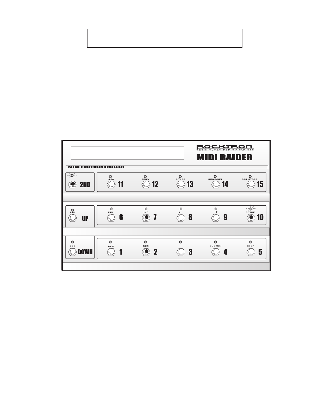
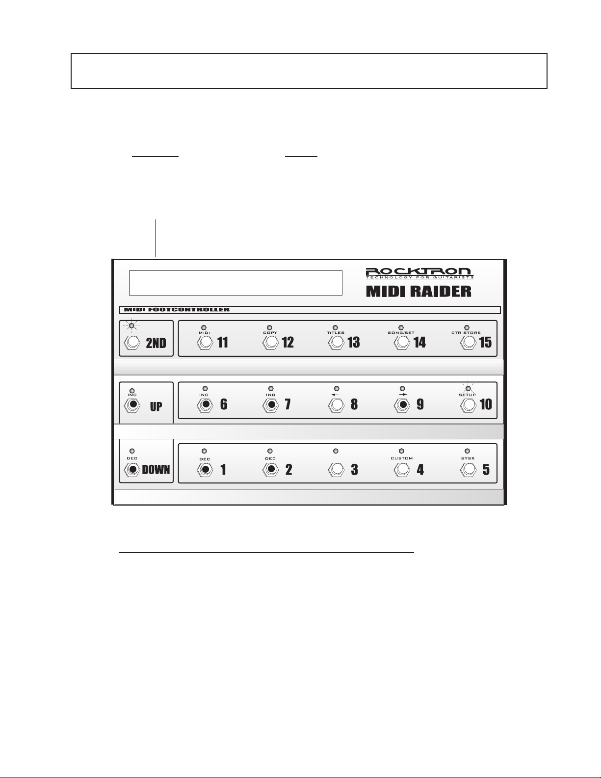
Top Panel
Primary button functions (2ND L.E.D. off) of the MIDI Raider footswitch
1
2
3
Bank UP/DOWN
switches
Switches 1-15
2ND switch
These switches allow for the selection of the preset bank (0-12).
These switches are used as preset switches and/or instant access
switches, dependent upon the conguration of the MIDI Raider.
(see SETUP, Pages 1 and 2)
This switch activates the secondary button functions. The secondary button functions are listed above each switch (see opposite
page)
2
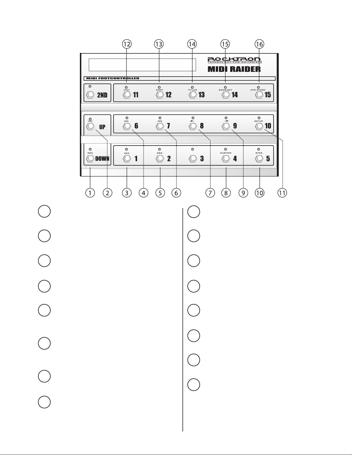
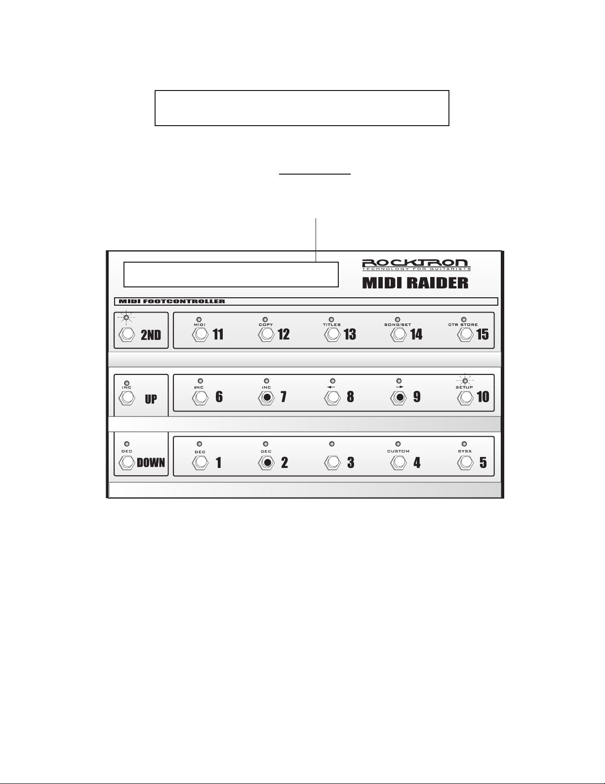
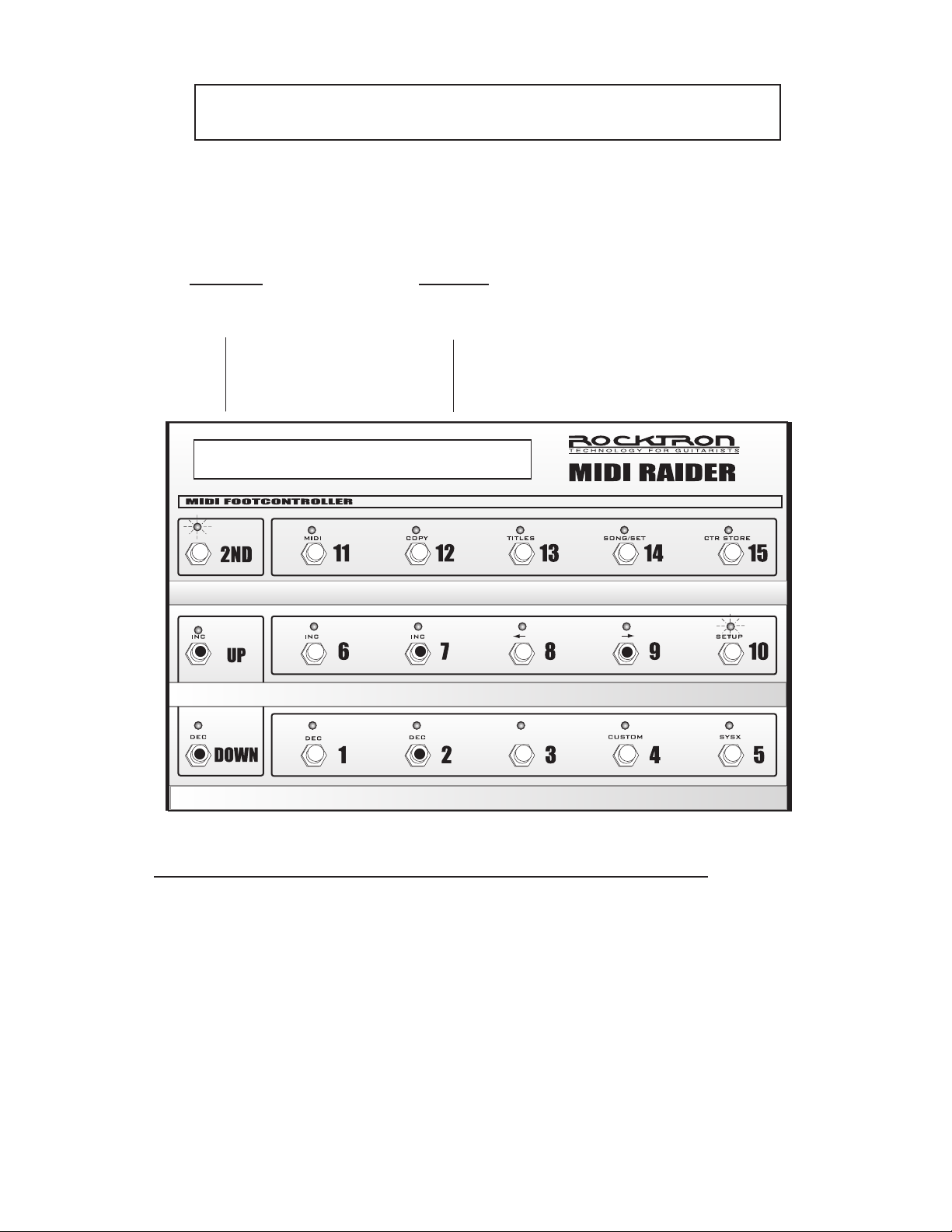
Secondary button functions (2ND L.E.D. on) of the MIDI Raider footswitch
DEC switch - used to decrement data selec-
1
tion currently shown on the left side of the
display.
2
INC switch - used to increment data selection
currently shown on the left side of the display.
3
DEC switch - used to decrement data selection currently shown in the center of the
display.
4
INC switch - used to increment data selection
currently shown in the center of the display.
5
DEC switch - used to decrement data selection currently shown on the right side of the
display.
6
INC switch - used to increment data selection currently shown on the right side of the
display.
7
switch - used to access the previous page
within an editing program.
8
9
switch - used to access the next succes-
sive page within an editing program.
10
SYSX switch - used to access the SYSX
editing program.
11
SETUP switch - used to access the SETUP
editing program.
12
MIDI switch - used to access the MIDI
editing program.
13
COPY switch - used to access the COPY
editing program.
14
TITLES switch - used to access the TITLES editing program.
15
SONG/SET switch - used to access the
SONG/SET editing program.
16
CTR/STORE switch - used to store the
current on/off status of the instant access
switches for the current preset.
CUSTOM switch - used to access the CUSTOM editing program.
3
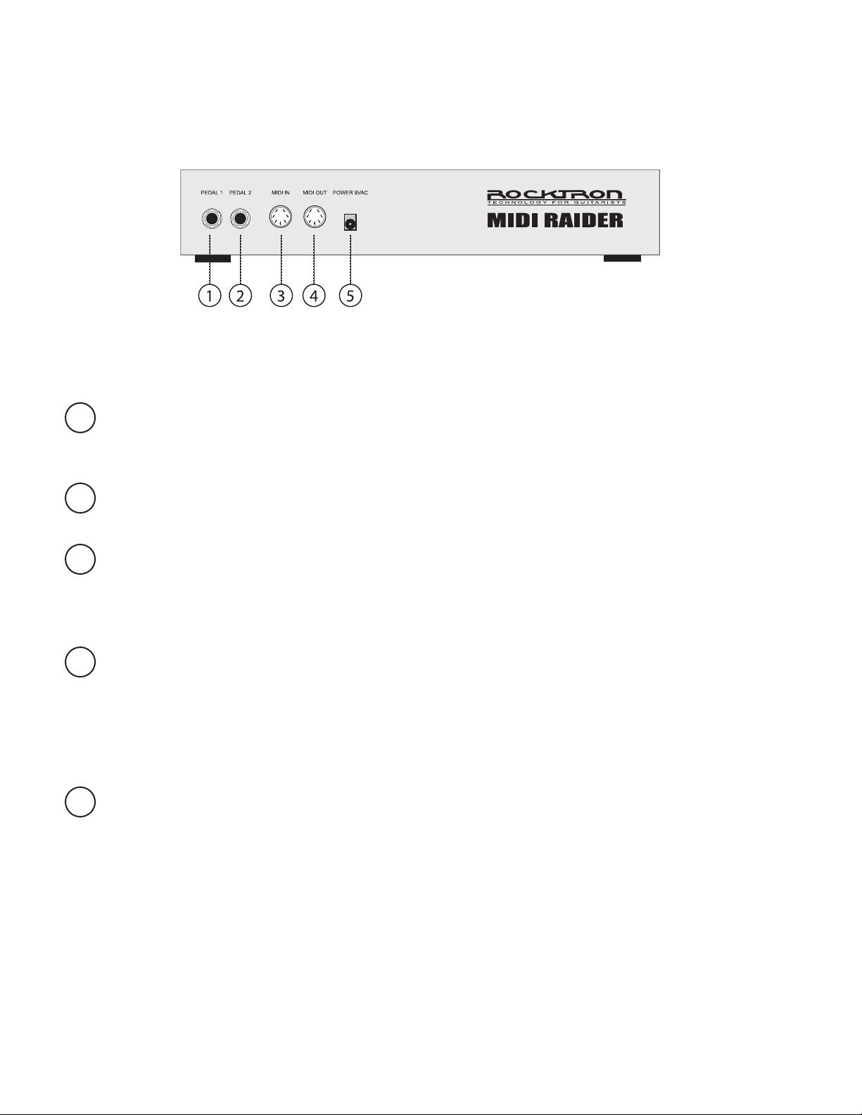
Rear Panel
PEDAL 1 jack
1
PEDAL 2 jack
2
MIDI IN jack
3
MIDI OUT jack
4
POWER jack
5
This ¼” stereo TRS jack allows for the connection of a continuous controller (such as an expression pedal, volume pedal, fader, etc.) to the MIDI
Raider.
This ¼” stereo TRS allows for the connection of a second continuous controller to the MIDI Raider.
This 7-pin DIN connector accepts the MIDI output signal from another
MIDI transmitting device which may be used to control the MIDI Raider. In
some applications, MIDI information will also be sent out through the MIDI
IN jack through pins 1 and 3.
This 7-pin DIN connector transmits MIDI information from the MIDI
Raider and connects to a MIDI receiving device or the rst in a chain of
MIDI receiving devices. In some applications, MIDI information will also
be received through the MIDI OUT jack through pins 1 and 3. Pins 6 and
7 of this connector provide phantom power to the MIDI Raider from your
rack.
This 2.5mm pin jack accepts power from the 9VAC adaptor
supplied with the unit.
4
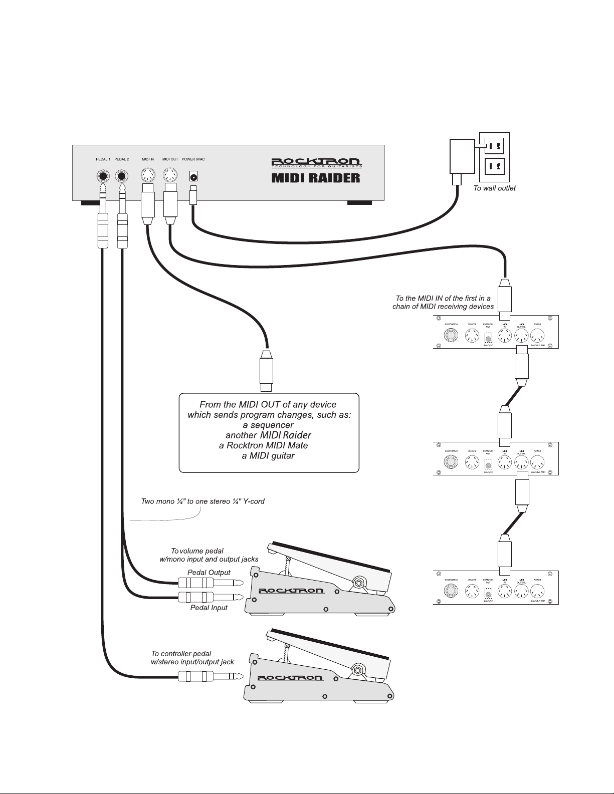
Typical Setup
5
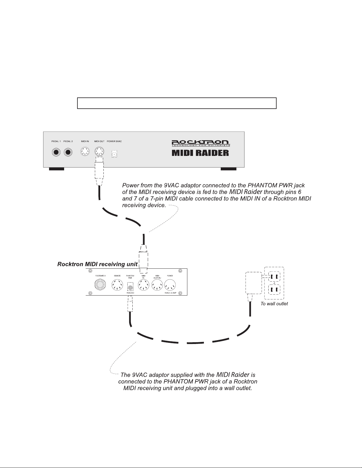
Using Phantom Power
Phantom power allows for the MIDI Raider to be powered from your rack (or from an AC outlet
near your rack) instead of running a long extension cord out across the stage to the footswitch.
Using phantom power with a Rocktron MIDI receiving device
6
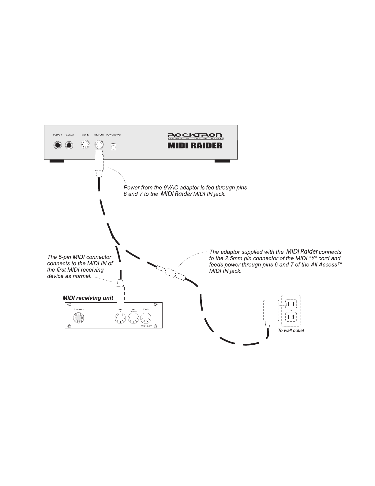
Using Phantom Power
Using phantom power with a non-Rocktron MIDI receiving device
7

Editing the MIDI Raider
The MIDI Raider can be congured to provide complete control over all of the MIDI receiving devices within a rack. This section discusses each of the following editing programs in detail:
SETUP
MIDI
COPY
TITLES
SONG/SET
CTR STORE
CUSTOM
SYSX
The MIDI Raider MIDI edit cycle on the following page can be used as a quick reference when
searching for specic MIDI Raider editing pages.
8
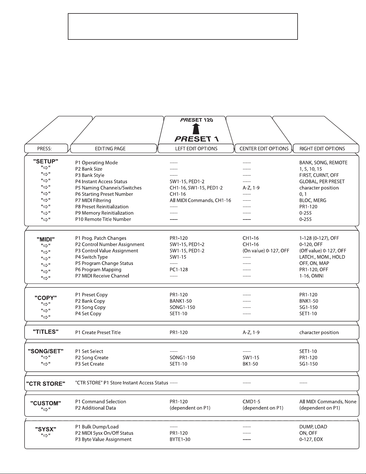
Quick Reference - MIDI Edit Cycle
The gure below lists all of the pages for each editing function, as well as the options which are
available for each editing page.
* Press “2ND” to access the following edit functions:
9

SETUP
The SETUP program allows the user to congure the general operation of the MIDI
Raider footswitch. Use the SETUP program to determine each of the following:
The operating mode;
The number of presets within each bank;
How presets are recalled when changing from bank to bank;
Assigning MIDI control values as sent globally or per preset;
Assigning names for MIDI channels;
The starting preset number for each MIDI channel;
MIDI ltering options;
Preset reinitialization;
Memory reinitialization;
Selecting a remote title number for use with other Rocktron products
Upon accessing SETUP, the rst page of the SETUP program, Operating Mode,
will automatically be displayed.
SETUP, Page 1 of 10 - Operating Mode
The rst page of the SETUP program determines the current operating mode of
the MIDI Raider. The MIDI Raider can be used in any of three different operating
modes - BANK, SONG or REMOTE.
When BANK mode is selected, presets are selected by rst “banking up” or
“banking down” via the “UP” and “DOWN” switches on the MIDI Raider. This selects
the Bank, or the rst two digits of the preset number (0-12). Depending upon the setting
of the BANK STYLE parameter (see SETUP, Page 2), the MIDI Raider will recall the
next preset based on the selected bank and either (a) the preset switch last selected from
the previous bank, (b) the rst preset in the newly selected bank, or (c) will not recall a
preset until an additional preset switch is pressed to select the preset number.
In SONG mode, the MIDI Raider allows for presets to be assigned to the preset switches
to create a SONG. Songs can then be arranged in a bank order to create a SET.
In REMOTE mode, the MIDI Raider acts as a remote control which can be
congured to control future remote compatible Rocktron products.
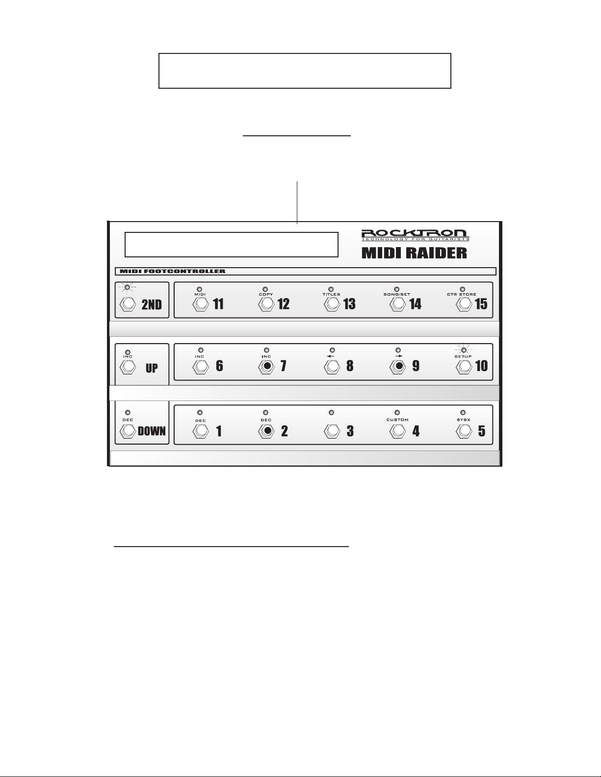
Accessing SETUP:
() To access the SETUP program, press the “2ND” button to activate the secondary
button functions.
() Press the “SETUP” button. The L.E.D. above the “SETUP” button will ash and
the MIDI Raider will display the rst page of the SETUP program. Pressing the
“” button while in the 2ND mode accesses each successive editing page.
10
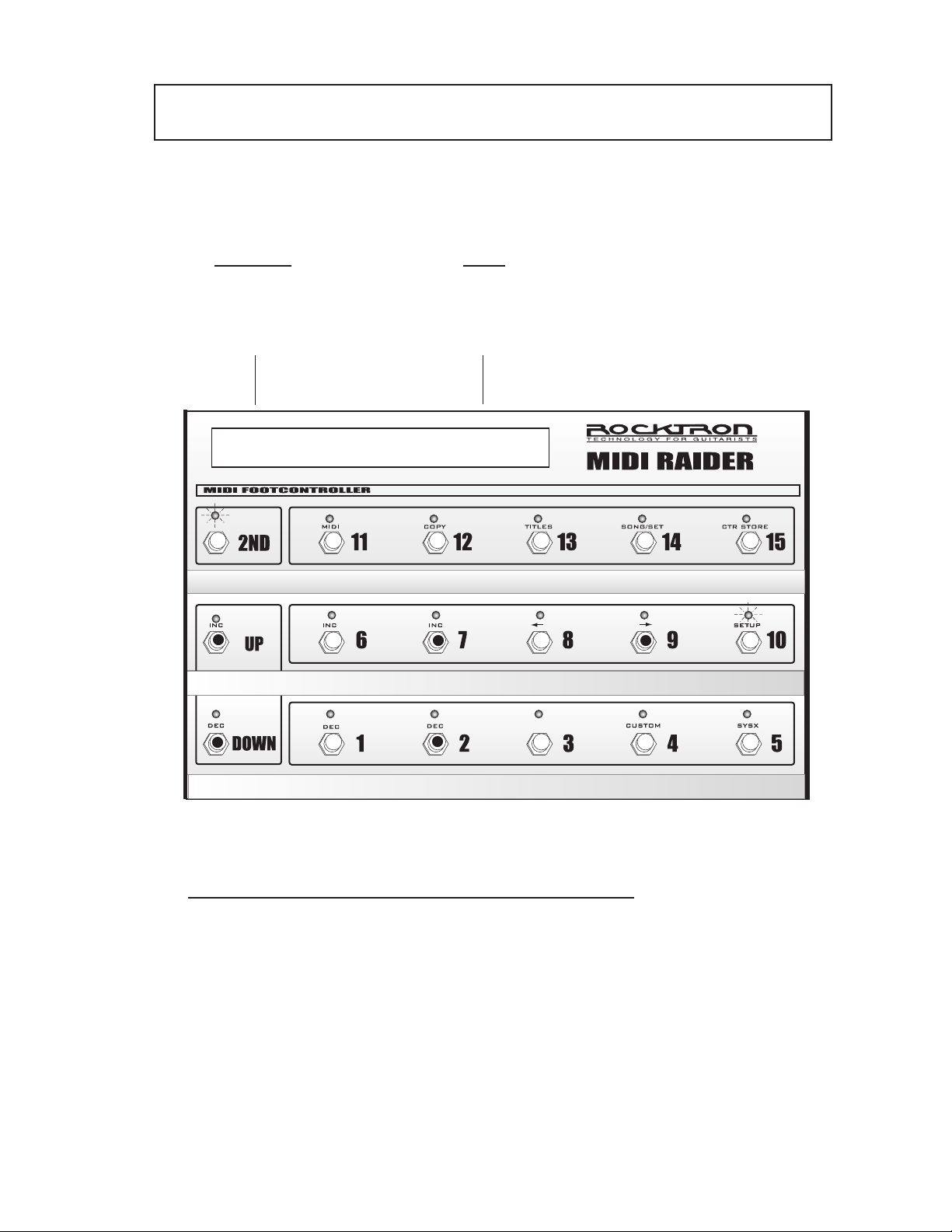
To select the operating mode:
() To select a different mode than the one displayed, press the “INC” or “DEC”
switches directly below the currently selected option on the right side of the
display. The selection will be automatically stored when this page is exited.
Selecting the operating mode
Mode Options
select
BANK, SONG
or REMOTE
MODE BANK
1
3
3
When the desired operating mode has been selected:
(a) press the “2ND” button again (turning the “2ND” L.E.D. off) to exit
the editing mode; or
(b) press the “” button to access additional SETUP editing pages; or
(c) press another mode button to edit MIDI Raider features other than
SETUP
2
11

SETUP, Page 2 of 10 - Bank Size
The second page of the SETUP program allows for the selection of the Bank
Size, or the number of presets that the MIDI Raider will bank up or down by
when the UP or DOWN switches are pressed.
When set to “5”, switches 1-5 become preset switches and the unit will bank
up or down by 5 presets at a time. When set to “10”, switches 1-10 become
preset switches and the unit will bank up or down by 10 presets at a time.
When set to “15”, switches 1-15 become preset switches and the unit banks
up or down by 15 presets at a time. When set to “1”, the unit banks up or
down by one preset at a time and all of the switches become instant access
switches.
The Bank Size setting also determines the number of preset switches for each
song when operating the MIDI Raider in Song mode.
About Preset and Instant Access Switches:
The MIDI Raider can be congured so that one row (switches 1-5), two rows
(switches 1-10) or three rows (switches 1-15) of switches can be dedicated as
preset switches, or switches that are used to select the various presets within
each bank. Preset switches send out commands which can recongure a
whole rack.
Any switches that are not congured as preset switches automatically become
instant access switches - or switches that are used to send specic MIDI
controller information on specic MIDI channels. Instant access switches
are used to switch in or out a specic effect or function on a MIDI receiving
device - thereby giving the user direct control over that specic effect or
function without affecting other effects, functions or presets within a rack of
devices.
Instant access switches can operate globally or per preset (see Setup, Page 4),
and each can be congured to operate as a latching, momentary or hold type
switch. (To congure instant access switches, refer to MIDI, Pages 2-4.)
To Select the Bank Size:
() With the MIDI Raider still in SETUP mode (2ND and SETUP L.E.D.s
lit), press the “" switch to access the second page of the SETUP pro-
gram, Bank Size. (If the MIDI Raider is not already in SETUP mode,
press “2ND”, then “SETUP”, followed by “" one time.)
() To select a new bank size, press the "INC" or "DEC" switches directly
below the currently selected option to scroll through the available
selections.
12
Selecting the Bank Size
Size Options
select
1, 5, 10 or 15
BANK BY 10
12
2
When the desired bank size has been selected:
(a) press the “2ND” button again (turning the “2ND” L.E.D. off) to exit
the editing mode; or
(b) press the “" button to access additional SETUP editing pages; or
(c) press another mode button to edit MIDI Raider features other than
SETUP.
13

SETUP, Page 3 of 10 - Bank Style
The third page of the SETUP program, Bank Style, determines how the next
preset will be recalled when the MIDI Raider is banked up or down. If the
Bank Style parameter is set to “First”, the rst preset in the new bank will
be recalled when the unit is banked up or down. If set to “Curnt”, the current
preset switch from the previous bank will be recalled. When set to “None”, an
additional preset switch must be pressed after banking up or down to recall the
desired preset.
FIRST - recalls the rst preset in the bank;
CURNT - recalls the preset based on the last preset switch pressed;
NONE - recalls a preset when a preset switch is pressed
To select the Bank Style:
() With the 2ND L.E.D. still lit, press the "" switch to access the next
page of the SETUP program, Bank Style. (If the MIDI Raider is not already in SETUP mode, press “2ND”, then “SETUP”, followed by “"
two times.)
() To select a different Bank Style, press the "INC" or "DEC" switch di-
rectly below the currently selected style to scroll through the available
options.
14
Selecting the Bank Style
Bank Style Options
select
FIRST, CURNT
or NONE
bANK style > first
12
2
When the desired bank style has been selected:
(a) press the “2ND” button again (turning the “2ND” L.E.D. off) to exit
the editing mode; or
(b) press the “" button to access additional SETUP editing pages; or
(c) press another mode button to edit MIDI Raider features other than
SETUP.
15

SETUP, Page 4 of 10 - Instant access switch
operating status
The fourth page of the SETUP program determines whether the
controller values sent from the MIDI Raider are global (the same
for all presets) or set on a per preset basis. When set to “GLOBAL”,
the controller channel, control number, “on” value and “off” value
that is sent when an instant access switch is pressed is the same for
all presets. When set to “PER PR”, the controller channel, control
number, “on” value and “off” value that is sent when an instant access
switch is pressed can be programmed for each individual preset.
Note:
When scrolling through the
switches to program, only
those switches which are
congured as instant access
switches can be accessed.
To change the instant access switch operating status:
() With the 2ND L.E.D. still lit, press the "" switch to access
the next page of the SETUP program. (If the MIDI Raider is
not already in SETUP mode, press "2ND", then "SETUP", followed by "" three times.)
() To select a specic instant access switch, use the "INC" and
"DEC" switches directly below the currently selected switch.
The current setting for each switch or pedal will be displayed.
() To select whether the displayed switch is congured as
"GLOBAL" or "PER PR", use the "INC" and "DEC" switches
directly below the currently displayed option.
16
Selecting the Instant access operating status
Switches to
Program
select
PED1-2
SW1-15
Operating
Type
select
GLOBAL or
PER PR
ped1 global
2
3
1
2
3
When the desired control value status has been selected:
(a) press the “2ND” button again (turning the “2ND” L.E.D. off) to exit
the editing mode; or
(b) press the “" button to access additional SETUP editing pages; or
(c) press another mode button to edit MIDI Raider features other than
SETUP.
17

SETUP, Page 5 of 10 - Naming MIDI Channels
The fth page of the SETUP program allows for custom 4 character
abbreviations to be shown in place of MIDI channels and instant
access switches during editing. Assigning a name to each MIDI
channel can make it considerably easier to remember which MIDI
devices are assigned to particular MIDI channels. This is also true of
instant access switches.
To assign a name to a MIDI channel or instant access switch:
() With the 2ND L.E.D. still lit, press the "" switch to access
the fth page of the SETUP program. (If the MIDI Raider is
not already in SETUP mode, press "2ND", then "SETUP", followed by "" four times.)
() To select a MIDI channel or switch to name, use the "INC"
and "DEC" switches directly below the currently selected
MIDI channel/switch to scroll through the available selections.
() Use the "INC" and "DEC" switches directly below the center
of the display to select the desired character for the current
position.
() Use the "INC" and "DEC" switches directly below the right
side of the display to advance to the next character position to
edit.
18
Naming MIDI Channels and Instant Access Switches
Channel/Switch
Channel
to Name
select
CH1-16
SW1-15
PED1, PED2
ch16 name->i.fex
2 3
4
Name
select
A-Z
1-9
1
2 3
4
When the desired channels and switches have been named:
(a) press the “2ND” button again (turning the “2ND” L.E.D. off) to exit
the editing mode; or
(b) press the “" button to access additional SETUP editing pages; or
(c) press another mode button to edit MIDI Raider features other than
SETUP.
19

SETUP, Page 6 of 10 - Starting Preset Number
Some MIDI devices may use “0” as the rst preset number of each
MIDI channel, while others may use “1”. This page of the SETUP
program allows for either “0” or “1” to be selected as the starting
preset number for each MIDI channel so that the preset number
displayed by the MIDI Raider matches the preset number displayed by
the MIDI device.
To select the starting preset number:
() With the 2ND L.E.D. still lit, press the "" switch to access
the next page of the SETUP program, Starting Preset Num-
ber. (If the MIDI Raider is not already in SETUP mode, press
“2ND”, then “SETUP”, followed by “" ve times.)
() To select a MIDI channel, use the "INC" and "DEC" switches
directly below the currently displayed MIDI channel (the
MIDI Raider displays the name of the channel given).
() To change the starting preset for the displayed MIDI channel,
use the "INC" and "DEC" switches directly below the currently displayed starting preset.
20
Selecting the Starting Preset Number
Selected
Channel
select
CH1-16
Starting Preset
Number
select
0 or 1
ifex pr start > 0
2 3
1
2 3
When the Starting Preset Number has been selected for each channel:
(a) press the “2ND” button again (turning the “2ND” L.E.D. off) to exit the edit-
ing mode; or
(b) press the “" button to access additional SETUP editing pages; or
(c) press another mode button to edit MIDI Raider features other than SETUP.
21
 Loading...