

Page 1
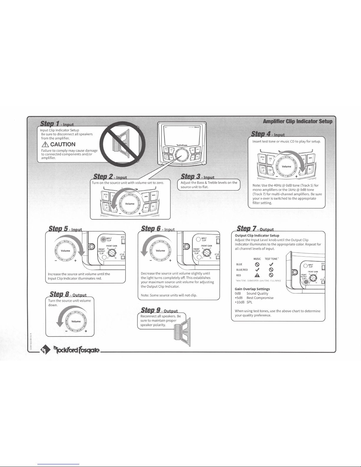
Input
Clip
Indicator
Setup
Be
sure
to
disconnect all speakers
from
the amplifier.
&_CAUTION
Failure
to
comply may cause damage
to
connected components
and/or
amplifier.
Amplifier
Clip
Indicator
Setup
Insert test
tone
or
music
CD
to
play for setup.
Turn on
the
source
unit
with
volume
set
to
zero.
Adjust the
Bass
& Treble levels on the
source
unit
to
flat.
Note:
Use
the 40Hz@
OdB
tone
(Track
5)
for
mono
amplifiers
or
the 1kHz@
OdB
tone
(Track
7)
for
multi-channel
amplifiers.
Be
sure
your
x-over
is
switched
to
the
appropriate
filter
setting.
Increase
the
source
unit
volume
until
the
Input
Clip Indicator illuminates red.
Turn the source
unit
volume
dow(0
2CH
[J
F
LPAP
lb!!
Decrease the source
unit
volume slightly
until
the
light
turns completely off. This establishes
your
maximum
source
unit
volume
for adjusting
the
Output
Clip Indicator.
Note: Some source units
will
not
clip.
Reconnect all speakers.
Be
sure
to
maintain
proper
speaker polarity.
Output Clip Indicator Setup
Adjust the
Input
Level knob
until
the
Output
Clip
Indicator
illuminates
to
the
appropriate
color. Repeat
for
all channel levels
of
input
.
BLUE
BLUE/RED
RED
MUSIC
TESTTONE
•
'
40Hz
TONE·
SUBWOOFER ·1kHz
TONE.
FULL
RA"GE
Gain Overlap Settings
OdB
Sound Quality
+SdB
Best Compromise
+lOdB
SPL
When using test tones, use the above chart
to
determine
your
quality
preference.
·~~~b.--------------------------------~
Page 2
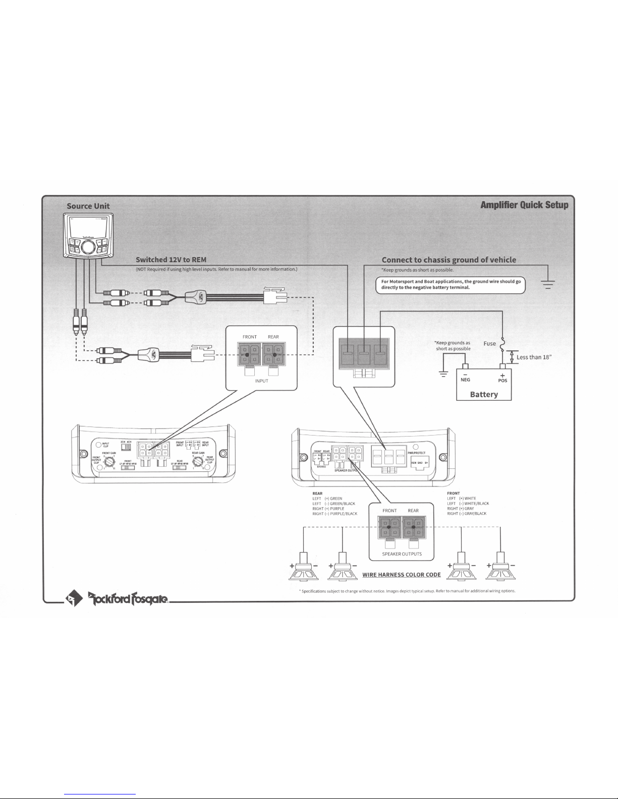
Source
Unit
Switched 12V to
REM
(NOT
Required
if
using high level inputs. Refer
to
manual for more
information
.)
FRONT
REAR
I
·----
INPUT
REAR
LE
FT
(+)GREEN
LEFT
(-)GREEN/BLACK
RIGHT (+) PURPLE
RIGHT(-)
PURPLE/BLACK
+
Amplifier
Quick
Setup
'Keep grounds
as
short
as
possible.
For
Motorsport
and
Boat
applications,
the
ground
wire
should go
directly
to
the
negative
battery
terminal.
SPEAKER
OUTPUTS
NEG
Battery
FRONT
LE
FT
(+) WHITE
LEFT
(-)W
HITE/BLACK
RIGHT (+)GR
AY
RIG
HT (-)GRAY/BLACK
+
POS
Less
than 18"
01~
WIRE
HARNESS COLOR CODE
~
~~~~
·
-------------------------------------------
··s
•p•ec.
ifi
•tc•at.io•n•ss•u•bJ.
·ec
•t•to•c•h•an•g•e•w•it.ho•u•t-no·t-ice_
.• lm•a•g-es•d•e-pi.ct•t-yp.ic•a•ls.et•u•p.•R•e•fe.r
t•o•m•a•nu•a•l•fo.ra•d•d-it.io.na•l•
w-iri•n-go•p·t'_·o.n
s •.
__________________
,
Page 3
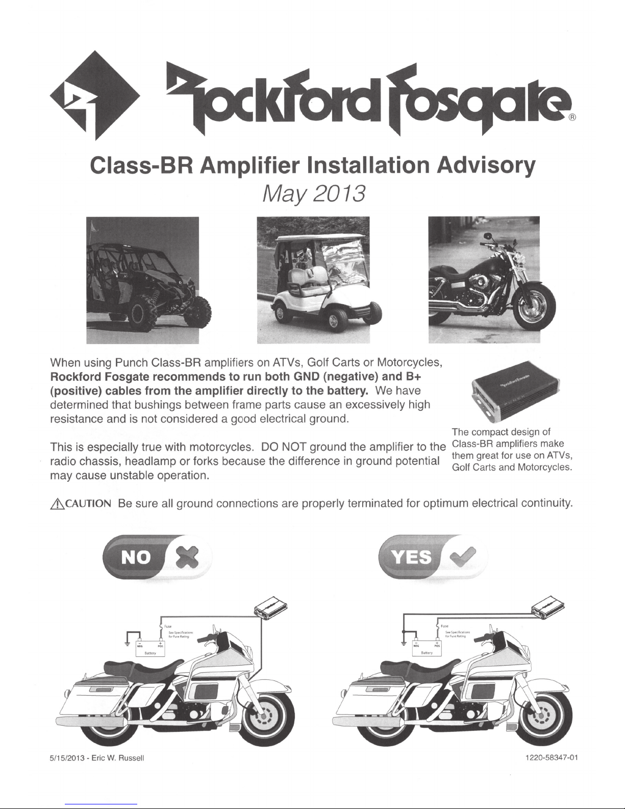
Class-BR Amplifier Installation
May 2013
Carts or Motorcycles,
When using Punch
Rockford Fosgate recommends to run both GND (negative) and
(positive) cables
determined that bushings between frame parts cause an
resistance and is not considered a good
especially
is
This
radio chassis head
may cause unsta e
'
Class-BR amplifiers
from the amplifier directly
true with
lamp
bl
operat1on.
motorcycles. DO NOT
or forks because the difference
·
on ATVs,
electrical
Golf
to the battery. We have
excessively high
ground.
ground
in
amplifier
potential
ground the
Advisory
8+
The compact design of
to the
Class-BR amplifiers
them great for use
Carts and
Golf
make
ATVs,
on
Motorcycles.
ground connections are
~CAUTION
5/15/2013 - Eric
Be sure
Russell
W.
all
properly
terminated for optimum electrical continuity.
__
-
-
8~ttery
·:
forFvw~
+
1220-5834
7-01
ft:t
- -
-
Page 4

Fuse and Battery Positive(+)
Run both
directly to battery terminals for optimum current delivery.
B+
(with fuse) and GND cables from amplifier
Battery Ground
Amplifier Mounting
Mount amplifier under motorcycle fairing
where it provides adequate air-flow.
(-)
5/15/2013 - Eric W. Russell
1220-5834 7-01
Page 5

E=====:
CERTIFICATE
OF
PERFORMANCE
VERIFICATION
===:====3i
~
Model#:
Idle
Current
Measure Current Draw at Idle
Current Draw
Frequency
< 100uA
Response
20Hz-20kHz Sweep @ 1 W
I
CHl
I PASS I CH21 PASS I CH
Remote
Level &
2/4/5
20Hz-20kHz Sweep @ 1 W
I
CH1
I
N/A
I CH
21
_J
<(
Common
z
20Hz-20kHz Sweep@
(.!)
C/)
C
Hl
I PASS I CH21 PASS I CH
Signal
to
Noise
Mode
N/A
Rejection
Ratio
20Hz-20kHz Sweep @ Rated
C
H1
I PASS I
Input
CH21
Sensitivity
PASS I CH
Check Sensitivity @ Minimum
C
H1
I PASS I
CH2
j PASS I CH
I CH
JI
Ch.
31
1W
JI
31
31
RMS
PASS I
Select
RMS
N/A
<[
Rated
RMS
PASS 1 CH
RMS
PASS I CH
PASS I C
08/29/2017 Test
CH1
High
Pass
Crossover
20Hz-20kHz Sweep @ W MS
4
1
CH
Check
PASS I
CHs
l
N/A
C
H1
I PASS I CH21 PASS J CH31 PASS I CH41 PASS I CH51
Low
Pass
Cross~~~
20Hz-20kHz Sweep @ W
CH4J
4
1
N/A
'
PASS I
I CH51
N/A
_l~
CH5
1
N/A
C
H1
I PASS
c
I~
PASS I C
nnel
Sep~tion
20f;1z-20kHz Sweep @ Rated
C
H1
I PASS j
Total
CH
21
Harmonic
PASS I
Distortion
Power 20Hz-20kHz Sweep@
41
PASS I CH
51
N/A
1 I 0.060 I
Total
CH21
Harmonic
0.070 I
Distortion
CH
20Hz-20kHz Sweep @ Rated
CH
H4
l
PASS I CH
51
/A
1 I
0.105 I
N
CH2l
0.028 I
C~k
Punch
RMS
H31
PASS I C
from
Left
CH3
1 PASS I CH
1W
RMS
CH3
1 0.077 I CH
Rated
CH3
1 0.035 I CH
System:
EO
H4
to
Right
RMS
Power
41
(%)
41
(%)
RMS
Power
41
RF-RATS-3
Check
1 PASS I
PASS I CH
0.066 I
0.166 I
CH51
51
CH51
CH51
N/A
N/A
N/A
N/A
N/A
Short
Protect
Sh
~
::J
Ill
<(
_J
w
((
((
w
~
0
a.
ALL Roc
conducted
©2012 Rockford Corporat
Co
rporation
without notice.
ort All Channels Sequentially@ 1%
C
H1
I
PASS I
Burn-In
Accelerated Life Monitor
CH I
PASS I TH I
Channel
2
CH
PASS I
1
Amplifier
PASS I v I
Power
CHJI
PASS I C
(45
PASS I
sec . @
Individual Channel Power@ 1% T
CH
1 I
12
7
Total
lcH2
Power
12
7 [cHJI
131
Total RMS Power @ Each Impedan
40
1
309 1
20
1 516 1 ,0 1
kford Fosgate amplifiers are designed, developed, manufactured and
at
14.4Vdc,
in
Min.
Impedance, 1kHz(ab/ad) or 100Hz (bd) unless otherwise stated.
ion.
the United States and/or other countries. All other trademarks are
All Rights
Reve
N/A
rsed.
ROCKFORD
THO
H4
1 PASS I CH
1%
T
BI
AS
I
N/A
HO
l CH
4l
131
ce@
1%
12/
10 I N/A I
FOSGATE,
51
N/A
Thermal
Th
TH1
I PASS I TH21
Test
ermistor Voltage Check
PASS I
TH3
1 N/A I TH41 N/A I
HO)
PASS
IIR
I
Total
Power
@2 0
I CH
THO
N/A
51
tes
ted
and associated logos where applicable are registered trademarks of Rockford
the
Total
RMS
Power@ 1% T
516
in
accordancE
property of their respective owners. Specifications subject
Nith
the CEA-2006 amplifier rating requirements.
HO
watts
to
change
All
tests
TH51
N/A
Page 6

Are
You
Engineered to Rock?
Get a One-Year Extended Warranty when
Amplifier
Installation
kit
you
use a matching
with
your
Rockford Fosgate
Amplifier!
We want you to get the performance and reliability that made Rockford Fosgate Amplifiers famous. Using poorquality under-spec wiring is a guaranteed way to get less than you paid for from your system.
We are so certain that getting your system wired to rock with the right wire and cables will make a difference, that we
will give you
an
additional 1 year warranty on your amp when you use the matching amplifier installation kit. See your
dealer to determine the matching kit for your amplifier.
To
extend your warranty under this program attach the serial number sticker or UPC code removed from the original
amplifier installation kit package
in
the box below. Keep this form along with your original purchase receipt.
One warranty extension per amplifier regardless of the number of amplifier kits purchased. Amplifier and wiring kit
must be purchased at the same time.
What
is
Covered
This warranty applies only to Rockford
Fosgate products sold to consumers by
Authorized Rockford Fosgate Dealers
in the United States
possessions. Product purchased
consumers from an Authorized Rockford
Fosgate Dealer in another country
are covered only by that country's
Distributor and not
Corporation.
of
America or its
by
Rockford
by
Who
is
Covered
This warranty covers only the original
purchaser
purchased from
Fosgate Dealer in the United States. In
order to receive service, the purchaser
must provide Rockford with a copy
the receipt stating the customer name,
dealer name, product purchased and
date
defective during the warranty period will
be repaired
deemed
discretion.
of
Rockford product
an
Authorized Rockford
of
purchase. Products found to be
or
replaced (with a product
to
be
equivalent)
at
Rockford's
of
What
is
Not
Covered
1. Damage caused by accident,
abuse, improper operations, water,
theft, shipping
2.
Any cost
removal
or
expense related to the
or
reinstallation
of
product
3. Service performed by anyone other
than Rockford or an Authorized
Rockford Fosgate Service Center
4. Any product which has had the
serial number defaced, altered,
removed
or
5. Subsequent damage to other
components
6. Any product purchased outside the
u.s.
7. Any product not purchased from
an Authorized Rockford Fosgate
Dealer
'
Limit
on
Implied
Any implied warranties including warranties of fitness for use and merchantability are limited in duration
express warranty set forth above. Some states do not allow limitations on the length of an implied warranty, so this limitation
may not apply. No person is authorized to assume for Rockford Fosgate any other liability in connection with the sa
product.
How
to
Obtain
The amplifier must be returned by the customer (you)
receipt and the ORIGINAL Performance Verification Certificate with the serial number or UPC code from the amp installation
kit. Contact your Authorized Rockford Fosgate Dealer
EU
Warranty
This product meets the current
"This Additional One-Year Warranty" is only available where allowed under local laws.
Warranties
Service
Under
the
Extended
EU
warranty requirements, see your Authorized dealer for details.
Warranty
Program
or
an authorized Rockford Fosgate retailer with a copy of the origina l
or
our Customer Support Specialists (1-800-669-9899) for assistance.
Attach Amplifier Installation Kit
or
Serial Number
UPC Code from
original packaging here.
to
the period of the
le
of the
Page 7

Page 8

 Loading...