

Page 1

AC690PRO & variants
de
Originalbetriebsanleitung
Klimaservicegerät
en
Original instructions
AC service units
fr
Notice originale
Appareil SAV pour la climatisation
es
Manual original
Aparato de servicios de
aire acondicionado
it
Istruzioni originali
Attrezzatura per assistenza
climatizzatore
pt
Manual original
Aparelho de manutencao de sistemas
de ar condicionado
M2
HIGH
LOW
P1
T1
T2
1
2
P
EV1
EV5
EV3
EV6
3 F1
C
P2
HP
5
VU2
6
F2
9
4
EV7
10
7
V18V3 V2V4
V6V5
M1
M3
13
12
11
EV10
VU3 VU1
EV8EV9
8
tuv
7
pqrs
0
1
4
ghi
V
abc
jkl
5
2
9
wxyz
def
mno
6
3
Page 2

8
tuv
7
pqrs
0
1
4
ghi
V
abc
jkl
5
2
9
wxyz
def
mno
6
3
14
15
16
18
19
17
20
22
23
21
26
25
24
Page 3

Italiano 4
English 44
Français 84
Deutsch 124
Español 164
Português 204
Page 4

• È proibita la riproduzione anche parziale di questo manuale in qualsiasi forma, senza
l’autorizzazione scritta da parte del produttore.
• I dati e le caratteristiche indicati in questo manuale non impeg nano il produttore, che si riserva il
diritto di apportare tutte le modifiche ritenute opportu ne senza obblighi di preavviso o sostituzione.
• Tutti i nomi di marchi e di prodotti o marchi registrati app artengono ai rispettivi proprietari.
S P00 D00 095 11/2013
Gentile autoriparatore,
vogliamo ringraziarla di aver scelto un nostro apparecchio per la Sua officina.
Siamo sicuri che trarrà da esso la massima soddisfazione e un notevole aiuto nel Suo
lavoro.
La preghiamo di leggere con attenzione le istruzioni contenute in questo manuale
operativo, da conservare con cura e a portata di mano per consultarlo ogni qualvolta ne
avrà l’esigenza.
AC690PRO è un’unità elettronica per il recupero, il riciclo, il vuoto e la carica degli
impianti A/C che impiegano R134a come gas refrigerante.
Un semplice ma affidabile sistema di allacciamento garantisce la sicurezza totale nello
svolgimento delle operazioni: recupero e riciclo del refrigerante; vuoto e prova tenuta;
iniezione di lubrificante o additivi; infine, ricarica del circuito e test della pressione di
esercizio.
Il flusso di refrigerante è controllato e gestito mediante bilancia elettronica, in modo da
rendere impossibile la tracimazione della bombola o l’afflusso di una quantità di
refrigerante superiore a quella consentita.
La quantità da caricare nell'impianto A/C viene programmata dall’operatore attraverso la
tastiera funzionale oppure consulta ndo il database interno.
Un distillatore-separatore consente la separazione del refrigerante dal lubr ifi c ante.
Page 5

________________________________________________________________________________ AC690PRO it
MANUALE OPERATIVO 5
Page 6

it AC690PRO ________________________________________________________________________________
6 MANUALE OPERATIVO
SOMMARIO
LEGENDA 8
INFORMAZION I GENERALI PER L’UTENTE 9
Smaltimento dell’apparecchio 9
Smaltimento delle batterie 9
1.0 - PER UN USO SICURO AC690PRO 10
1.1 - Per un uso sicuro 10
1.2 - Dispositivi di sicurezza 11
1.3 - Ambiente operativo 12
1.4 - Collaudo bombola 12
2.0 - INTRODUZIONE ALL'UNITÀ 13
3.0 - DESCRIZIONE DELL’UNITÀ 14
3.1 - La tastiera 14
4.0 - INSTALLAZIONE DELL’UNITÀ 15
4.1 - Disimballo e controllo dei comp onenti 15
4.2 - Movimentazione e stoccaggio della macchina 15
4.3 - Preparazione all’uso 16
4.4 - Memorizzazione refrigerante caricato e recuperato 20
4.4.1 - Abilitazione gestione report 20
4.4.2 - Stampa report 20
4.4.3 - Gestione report con ACUSB (optional) 20
4.5 - Riempimento bombola 21
4.6 - Visualizzazione bombola 22
4.7 - Autozero bilance olio 22
5.0 - USO DELL’UNITÀ 23
5.1 - Inserimento dati veicolo 23
5.2 - Database 23
5.3 - Database personale 26
5.4 - Recupero del refrigerante 27
5.5 - Evacuazione dell'impianto A/C 28
5.6 - Iniezione olio e carica impianto A/C 29
5.7 - Funzione automatica 30
5.8 - Funzione di riciclaggio 32
5.9 - Carica incompleta 32
5.10 - Flushing (optional) 33
Page 7

________________________________________________________________________________ AC690PRO it
MANUALE OPERATIVO 7
6.0 - MESSAGGI VISUALIZZATI A DISPLAY 34
6.1 - Messaggi di servizio 34
6.2 - Messaggi di errore 34
7.0 - MANUTENZIONE 35
7.1 - Sostituzione olio pompa di vuoto 35
7.2 - Azzeramento contatore olio pompa di vuoto 35
7.3 - Sostituzione filtro deidratatore 36
7.4 - Azzeramento del contatore filtro deidratatore 37
7.5 - Taratura bilancia refrigerante 38
7.6 - Taratura bilancia reintegro olio 39
7.7 - Taratura bilancia scarico olio 40
8.0 - ARRESTO PER LUNGHI PERIODI 41
9.0 - DEMOLIZIONE/SMALTIMENTO 41
9.1 - Smaltimento delle attrezzature 41
9.2 - Smaltimento dei materiali ricicl ati 41
10.0 - CARATTERISTICHE TECNIC HE 42
11.0 - PARTI DI RICAMBIO 42
12.0 - GLOSSARIO DEI TERMINI 43
Page 8

it AC690PRO ________________________________________________________________________________
8 MANUALE OPERATIVO
LEGENDA
M1 Manometro bassa pressione
M2 Manometro alta pressione
M3 Manometro serbatoio interno
T1 Tubo di servizio bassa pressione
T2 Tubo di servizio alta pressione
LOW Valvola bassa pressione gruppo manometrico
HIGH Valvola alta pressione gruppo manometrico
V1 Valvola tubo lato vapore bombola
V2 Valvola tubo lato liquido bombola
V3 Valvola lato vapore bombola
V4 Valvola lato liquido bombola
V5 Valvola di sicurezza
V6 Valvola scarico in condensabili
VU1 Valvola unidirezionale di protezione olio
VU2 Valvola di non ritorno distillatore
VU3 Valvola unidirezionale di protezione tracciante
F1 Filtro meccanico linea recupero
F2 Filtro deidratatore
EV1 Elettrovalvola linea vuoto
EV3 Elettrovalvola di separazione c i r c ui to
EV5 Elettrovalvola di recupero/riciclo
EV6 Elettrovalvola di carica
EV7 Elettrovalvola scarico olio
EV8 Elettrovalvola reintegro olio
EV9 Elettrovalvola iniezione liquido di contrasto
EV10 Elettrovalvola di separazione alta/bassa pressione
1 Ampolla reintegro olio
2 Pompa per vuoto
3 Regolatore di pressione
4 Distillatore-separatore per olio recuperato
5 Distillatore-separatore per olio compressore
6 Compressore
7 Bombola di stoccaggio
8 Bilancia elettronica
9 Ampolla scarico olio
10 Scambiatore di calore
11 Ampolla car i c o liquido di contrasto
12 Bilancia reintegro olio
13 Bilancia scarico olio
P1 Trasduttore di pressione
P2 P ressostato di alta pressione
Page 9

________________________________________________________________________________ AC690PRO it
MANUALE OPERATIVO 9
INFORMAZIONI GENERALI PER L’UTENTE
Smaltimento dell’apparecchio
• Non smaltire queste apparecchiature come rifiuto municipale solido misto ma
effettuare una raccolta separata.
• Il reimpiego o il corretto rici claggio delle apparecchiature elettriche ed elettroniche
(AEE) è importante per preservare l’a mbiente e la salute umana stessa.
• Secondo la Direttiva Europea RAEE 2002/96/EC sono disponibili specifici centri di
raccolta a cui consegnare i rifiuti di apparecchiature elettriche ed elettroniche.
• La pubblica amministrazione ed i produttori di AEE sono impegnati ad agevolare i
processi di reimpiego e recupero dei rifiuti di AEE attraverso l’organizzazione delle
attività di raccolta e attraverso l’util izzo di opportuni accorgimenti progettuali.
• La legge punisce con opportune sanzi oni chi smaltisce abusivamente i rifiuti di AE E.
Smaltimento delle batterie
• È necessario riciclare le batterie o disfarsene in modo appropriato.
Non gettare le batterie nei rifiuti urbani.
• Non gettare le batterie nel fuoco!
Page 10
it AC690PRO ________________________________________________________________________________
10 MANUALE OPERATIVO
1.0 - PER UN USO SICURO AC690PRO
L’avanzata tecnologia utilizzata per progettazione e produzione fa dell’AC690PRO
un’unità estremamente semplice ed affidabile nello svolgimento di tutte le operazioni.
Pertanto l’utente, seguendo le regole generali di sicurezza riportate più oltre, facendo
un uso proprio della unità e mantenendola correttamente, non è soggetta ad alcun
rischio.
NOTA BENE:
Questa unità è destinata esclusivamente ad operatori professionalmente preparati che
devono conoscere i fondamenti della refri gerazione, i sistemi frigoriferi, i gas refrigera nti
e gli eventuali danni che possono provocare le apparecchiature in pressione.
Si richiede una attenta lettura del presente manuale da parte dell'utilizzatore, per il
corretto e sicuro impiego dell'a pparecchiatura.
1.1 - Per un uso sicuro
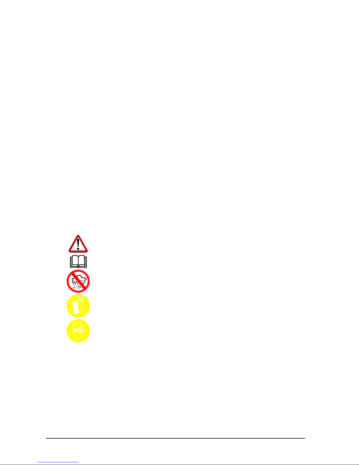
• È obbligatorio indossare adeguate protezioni quali occhiali e guanti, il contatto con
il refrigerante può provocare cecità e altri danni fisici all'operatore. Fare riferimento
alla simbologia qui sotto riportata:
Leggere attentamente le istruzioni.
Non usare all'aperto in condizi oni di pioggia o forte umidità.
Obbligo di usare guanti.
Obbligo di usare occhiali di p r otezione.
• Evitare il contatto con la pelle, la bassa temperatura di ebollizione (circa -30 °C)
può provocare congelamenti.
• Evitare l’inalazione dei vapo r i dei gas refrigeranti.
• Prima di effettuare collegamenti fra l'unità AC690PRO ed un impianto A/C o un
contenitore esterno, verificare che tutte le valvole siano chiuse.
Page 11

________________________________________________________________________________ AC690PRO it
MANUALE OPERATIVO 11
• Prima di scollegare l'unità AC690PRO, verificare che il ciclo sia stato completato e
che tutte le valvole siano chiuse, si evita così di disperdere il gas refrigerante
nell’atmosfera.
• Non modificare la taratura delle valvole di sicurezza e dei sistemi di control lo.
• Non utilizzare serbatoi esterni o altri contenitori di stoccaggio che non siano
omologati oppure privi di valvole di sicurezza.
• Non lasciare l’unità sotto tensione se non se ne prevede l’utilizzo immediato,
interrompere l'alimentazione elettrica prima di un lungo periodo di inattività della
unità oppure prima di effettuare dei lavori di manutenzione interna.
• Durante le operazioni di manutenzione fare attenzione perché i tubi di
collegamento potrebbero contenere refrigerante sotto pressione.
• Non utilizzare l’unità in ambi enti esplosivi.
Gli interventi di manutenzione straordinaria devono essere eseguiti solo da personale
autorizzato.
• La pressione o le perdite delle apparecchiature di servizio HCF-134a o dei sistem i di
aria condizionata del veicolo non devono essere provate con aria compressa.
Alcune miscele di aria/HCF-134a sono combustibili a pressioni elevate.
Queste miscele sono potenzialmente pericolose e possono causare incendi o
esplosioni con conseguenti infort uni o danni materiali.
Ulteriori informazioni relative alla salvaguardia della salute umana e della sicurezza
possono essere otten ute dai produtt ori del refrigerante.
1.2 - Dispositivi di sicurezza
L’AC690PRO è dotata dei seguenti dispositivi di sicurezza:
• Valvole di sovrapressione.
• In aggiunta alla valvola di sovrapressione è stato inserito un pressostato di
massima pressione che interviene arrestando il compressore in caso di eccessiva
pressione.
ATTENZIONE:
Non è ammesso alcun t ip o d i ma no mi ssio ne dei d isposit ivi di sicurezza
sopracitati.
Page 12
it AC690PRO ________________________________________________________________________________
12 MANUALE OPERATIVO
1.3 - Ambiente operativo
• L'unità deve funzionare in ambient e suffic ientemente aerato.
ATTENZIONE:
Lavorare a distanza da fiamme libere e superfici calde; alle alte
temperature il gas refrigerante si de
compone liberando sostanze
tossiche e aggressive, dannose per l'operatore e per l'ambiente.
• Per un corretto funzionamento, l'unità deve operare in piano; anche durante brevi
spostamenti, evi tare di sottoporl a a scuotimento eccessivo.
• Non sottoporre a vibrazioni l'unità AC690PRO.
ATTENZIONE:
Durante le varie operazioni, evitare assolutamente di disperdere in
ambiente il refrigerante. Tale precauzione, oltre ad essere richiesta
dalle norme internazionali a tutela dell’ambiente, è indispensabile al
fine d
i evitare che la presenza di refrigerante in ambiente renda
difficile la localizzazione delle eventuali perdite.
• Lavorare in ambienti sufficientemente illum inati.
• Evitare di inalare i refrigeranti e gli oli degli impianti. L’esposizione può irritare gli
occhi e le vie respiratorie. Per rimuovere R134a dall’impianto A/C, utilizzate
solamente unità adatte al riciclaggio dell’R134a. Se avvengono emissioni
accidentali di refrigerante in atmosfera, ventilate l’area di lavoro prima di
ricominciare il servizio.
• Non utilizzare l’unità sotto l’azione diretta del sole; l’esposizione al sole può causare
temperature eccessive e mal funzionamenti. Le temperature di esercizio indicate
sono riferite all’unità non esposta direttamente al sole.
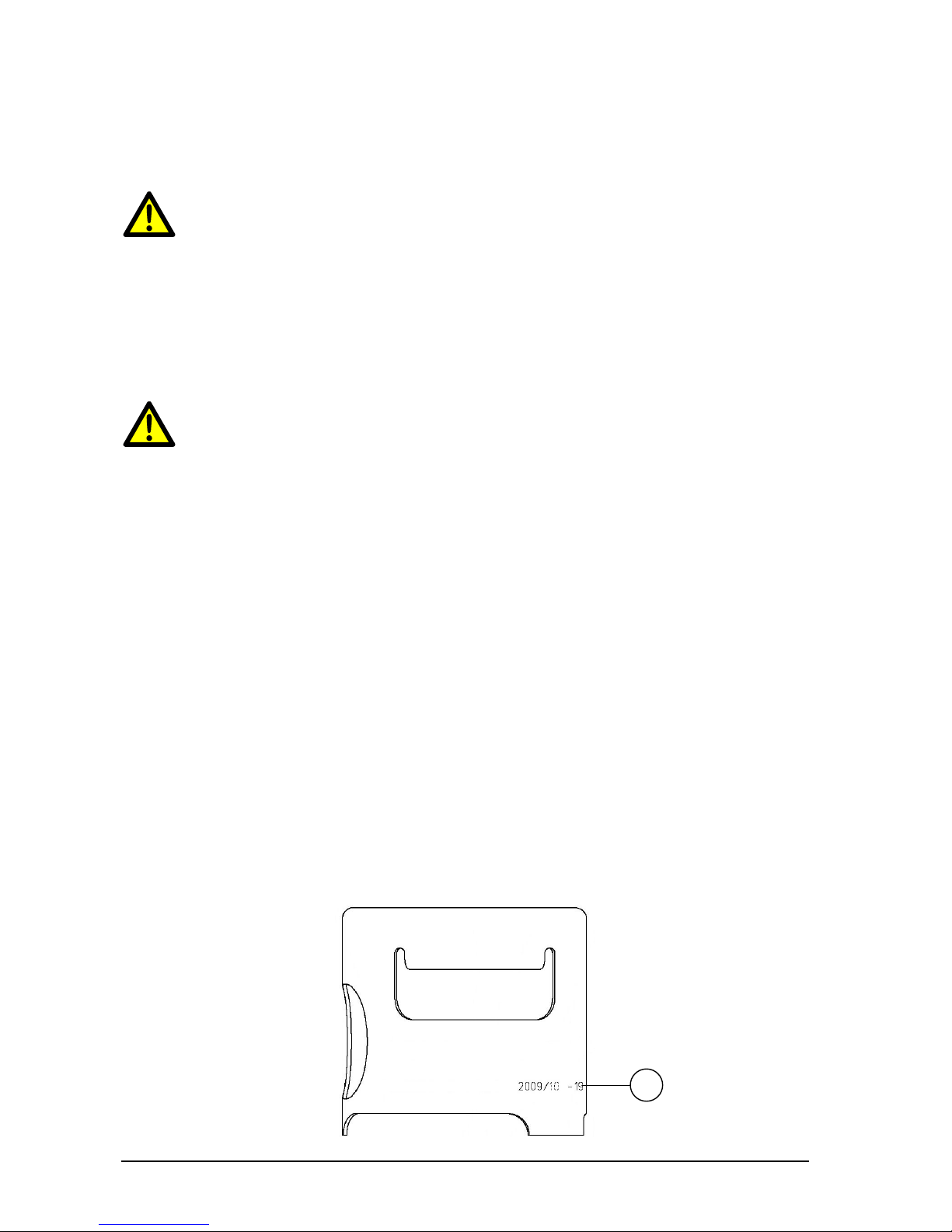
1.4 - Collaudo bombola
La bombola deve essere ricollaudata o sostituita ogni 10 anni. Verificare la data di
ricollaudo (1) sul collare della bombola stessa.
1
Page 13

________________________________________________________________________________ AC690PRO it
MANUALE OPERATIVO 13
2.0 - INTRODUZIONE ALL'UNITÀ
L’unità AC690PRO è adatta per il servizio su tutti i condizionatori/climatizzatori
funzionanti con gas refrigerante R134a che equipaggiano autovetture, camion e veicoli
industriali.
Il microprocessore che equipaggia l'unità AC690PRO, permette di gestire tutte le
funzioni tramite l’utilizzo di una bilancia elettronica, un LCD per la visualizzazione dei
valori in peso o in minuti e di messaggi di aiuto delle diverse procedure selezionate e un
pannello di comando con tasti era alfanumerica.
Collegando l'unità AC690PRO ad un impianto A/C, il gas refrigerante potrà essere
recuperato, riciclato, pronto per essere immesso di nuovo nell'impianto stesso dopo
avere effettuato una buona evacuaz ione.
È possibile misurare la quantità di lubrificante sottratta all'impianto A/C durante il
recupero del refrig erante e successivam en te reintegrarlo.
L’unità è equipaggiata con una pompa bistadio per alto vuoto e con un gruppo
manometrico per il monitoraggio continuo delle operazioni in corso.
La verifica di tenuta dell'impianto A/C viene effettuata mediante i manometri dell’unità
stessa.
L’unità è dotata di speciali raccordi per evitare contaminazioni con sistemi che utilizzano
R12.
ATTENZIONE:
Non cercare di adattare questa unità per condizionatori/climatizzatori
che utilizzano R12.
Page 14

it AC690PRO ________________________________________________________________________________
14 MANUALE OPERATIVO
3.0 - DESCRIZIONE DELL’UNITÀ
14. Tastiera.
15. Manometro bassa pressione.
16. Manometro alta pressione.
17. Manometro serbatoio interno.
18. Valvola alta pressione.
19. Valvola bassa pressione.
20. Stampante.
21. Interruttore generale alimentazione.
22. Tubo per collegamento alta pressione.
23. Tubo per collegamento bassa pressione.
24. Contenitore iniezione olio.
25. Contenitore iniezione liquido di contrasto.
26. Contenitore scarico olio.
3.1 - La tastiera
27. Led funzione di RECUPERO.
28. Tasto funzione di RECUPERO.
29. Led funzione di VUOTO.
30. Tasto funzione di VUOTO e movimento cursore verso l’alto.
31. Led funzione di CARICA.
32. Tasto funzione di CARICA e movimento cursore verso destra.
33. Led funzione AUTOMATICA.
34. Tasto funzione AUTOMATICA e movimento cursore verso sinist r a.
35. Led funzione di FLUSHING.
36. Tasto funzione di FLUSHING e movimento cursore verso il basso.
37. Tasto MENU (menù, cancellazione, by-pass e pausa).
38. Tasto funzione DATI VEICOLO e DATABASE.
39. Porta per aggiornamenti software.
40. Tasto STOP.
41. Tasto ENTER.
42. Display.
Page 15

________________________________________________________________________________ AC690PRO it
MANUALE OPERATIVO 15
4.0 - INSTALLAZION E DELL’UNITÀ
Di seguito verranno descritte le operazioni da effettuare per la messa in funzione
dell’unità.
4.1 - Disimballo e controllo d ei componenti
• Rimuovere l’imballo della macchina.
• Controllare la presenza di tutti i componenti accessori:
Manuale d’uso.
N°1 Bicchiere graduato.
N°2 raccordi bombola.
Certificato di conformità della valvola di sicurezza della bombola.
4.2 - Movimentazione e stoccaggio della macchina
Togliere l’unità dal bancale di ba se d ell’imballo.
L’unità viene movimentata sulle quattro ruote; le due anteriori sono frenabili.
Su terreni accidentati l’AC690PRO può venire spostata mantenendola inclinata ed
appoggiata a terra sulle due ruote posteriori.
Nonostante i componenti più pesanti dell’unità siano stati installati sul fondo per
abbassare il baricentro non è stato possibile eliminare totalmente il
rischio di rovesciamento.
Page 16

it AC690PRO ________________________________________________________________________________
16 MANUALE OPERATIVO
4.3 - Preparazione all’uso
Prima di iniziare ad utilizza r e la st azione AC690PRO, è possibile personalizzarla.
Questi settaggi non sono obbligat ori sui modelli standard.
Per personalizz are la stazione A/C procedere come segue:
• Accendere la stazione ed attendere la visualizzazione della pagina di STAND-BY
(data e ora).
• Premere contemporaneamente i tasti 3 e FLUSHING (36) per alcuni secondi.
• Il display visualizza 0000.
• Digitare il codice 2222.
• Il display visualizza un menù con le opera zioni che si possono eseguire.
• Premere il tasto movimento cursore verso l’alto (30) o verso il basso (36) per far
scorrere il menù.
• Selezionare la funzione desiderata e premere ENTER per entrare.
• Premere STOP per tornare alla pagina STAND-BY.
CAMBIO LINGUA
• Selezionare la funzione CAMBIO LINGUA e premere ENTER.
• Il display visualizza l’elenco delle lingue disponibili in memoria.
• Premere il tasto movimento cursore verso l’alto (30) o verso il basso (36) per far
scorrere il menù e premere ENTER (41) per impostare la lingua scelta.
• Il display visualizza nuovament e il m enù principale.
UNITÀ DI MISURA
• Selezionare la funzione UNITÀ DI MISURA e premere ENTER.
• Il display visualizza l’elenco delle unità di misura disponibili in memo r ia.
• Premere il tasto movimento cursore verso l’alto (30) o verso il basso (36) per far
scorrere il menù e premere ENTER (41) per impostare l’unità di misura scelta .
• Il display visualizza nuovament e il m enù principale.
Page 17

________________________________________________________________________________ AC690PRO it
MANUALE OPERATIVO 17
DATA E ORA
• Selezionare la funzione DATA E ORA e premere ENTER.
• Il display visualizza la data e l’ ora correnti e il cursore si posiziona sulla data.
• Digitare la data e premere ENTER per confermare.
• Il cursore si posiziona sull’ora.
• Digitare l’ora e premere ENTER per confermare.
• Il display visualizza nuovament e il m enù principale.
LUNGHEZZA TUBI
È possibile fornire su richiesta, dei tubi di servizio più lunghi (optional), in questo caso è
necessario settare la macchina affinché durante la carica compensi la variazione di
refrigerante che rimane nei tubi. I tubi in dotazione standard sono di 2,5 m.
• Selezionare la funzione LUNGHEZZA TUBI e premere ENTER.
• Il display visualizza la lunghezza standard dei tubi optional.
• Premere il tasto movimento cursore verso l’alto (30) o verso il basso (36) per far
scorrere il menù e premere ENTER per impostare la lunghezza scelta.
• Il display visualizza nuovament e il m enù principale.
DATI OFFICINA
Per inserire i dati officina sono di sp onibili 8 righe di 20 caratteri.
L’inserimento dei dati avviene da tastiera in modo analogo ai telefoni cellulari:
• Selezionare la funzione DATI OFFICINA e premere ENTER.
• Premere i tasti numerici per selezionar e lettere e caratteri .
• Premere i tasti movimento cursore per spostarsi nelle diverse righe.
• Premere il tasto MENU (37) per cancellare il carattere che precede il cursore.
• Premere ENTER per memorizzare l’inserimento dei dati officina.
• Il display visualizza nuovament e il m enù principale.
Page 18

it AC690PRO ________________________________________________________________________________
18 MANUALE OPERATIVO
CONTRASTO
• Selezionare la funzione CONTRASTO e premere ENTER.
• Il display visualizza un indice numerico d el grado di contrasto.
• Premere il tasto movimento cursore verso l’alto (30) o verso il basso (36) per
modificare il contrasto e premere ENTER per confermare.
• Il display visualizza nuovament e il m enù principale.
FLUSHING
È possibile montare sulla stazione A/C il Kit opzionale per il lavaggio dei componenti.
Se la stazione è dotata di tale Kit, occorre inserirlo nei parametri interni affinché abiliti
la funzione.
• Selezionare la funzione FLUSHING e premere ENTER.
• Il display visualizza ABILITATO e DISABILITATO.
• Premere il tasto movimento cursore verso l’alto (30) o verso il basso (36) per
selezionare ABILITATO o DISABILITATO e premere ENTER per confermare.
• Il display visualizza nuovament e il m enù principale.
BILANCE OLIO
È possibile, in caso di mal funzionamento, disabilitare le bilance di reintegro e di scarico
olio per non bloccare la stazione.
• Selezionare la funzione BILANCE OLIO e premere ENTER.
• Il display visualizza ABILITATO e DISABILITATO.
• Premere il tasto movimento cursore verso l’alto (30) o verso il basso (36) per
selezionare ABILITATO o DISABILITATO e premere ENTER per confermare.
• Il display visualizza nuovament e il m enù principale.
Page 19

________________________________________________________________________________ AC690PRO it
MANUALE OPERATIVO 19
TRACCIANTE
Questo menù viene utilizzato per indicare a display la richiesta di inserimento del
tracciante prima della funzione di carica.
• Selezionare la funzione TRACCIANTE e premere ENTER.
• Il display visualizza ABILITATO e DISABILITATO.
• Premere il tasto movimento cursore verso l’alto (30) o verso il basso (36) per
selezionare ABILITATO o DISABILITATO e premere ENTER per confermare.
• Il display visualizza nuovament e il m enù principale.
ATTENZIONE:
Per evitare problemi dovuti a incompatibilità chimica con i
componenti interni dell'unità A/C, ut ilizzare solo i liquidi di contrasto
selezionati e forniti da Ro binair. Tutt i i problemi causat i dal l’ut
ilizzo di
liquidi di contrasto diversi da quelli indicati, annullano la garanzia
dell’unità A/C.
AGGIORNAMENTO DATABASE
Questo menù viene utilizzato per l’aggiornamento del database case auto.
• Inserire la chiavetta di aggiornamento sulla parte frontale della scheda.
• Selezionare la funzione AGGIORNAMENTO DB e premere ENTER.
• Al termine dell’operazione la sched a si ripristina automaticamente.
• Togliere la chiavetta.
NOTA BENE:
Non spegnere l’unità A/C durante l’aggiornamento.
INSERIMENTO NUMERO DI SERIE
• Selezionare la funzione NUMERO DI SERIE e premere ENTER.
• Inserire il numero di serie della stazione (presente nella targhetta dati tecnici
fissata nella parte posteriore della stazione) con i tasti numerici e premere ENTER.
• Il display visualizza nuovament e il m enù principale.
NOTA BENE:
È necessario inserire solamente le ultime 5 cifre del numero di serie in quanto la prima
cifra viene inserita automati cam ente dal programma.
Page 20

it AC690PRO ________________________________________________________________________________
20 MANUALE OPERATIVO
4.4 - Memorizzazione refrigerante caricato e recuperato
Se si desidera memorizzare e successivamente stampare i dati del refrigerante caricato e
recuperato bisogna abilitare la funzione “Gestione Re port”. Dal momento in cui viene fatta
l’abili t azione t utti i dat i d e l r ef r ig e rante cari ca t o e r e c up e ra t o ve ng ono memor iz z ati.
4.4.1 - Abilitazione gestione report
Per abilitare la f u n zione gestione report procedere come segue:
• Premere i tasti 3 e FLUSHING contemporaneamente per alcuni secondi.
• Il display visualizza 0000.
• Digitare il valore 5599.
• Il display visualizza un menù di funzioni.
• Premere il tasto movimento cursore verso l’alto (30) o verso il basso (36) per
selezionare GESTI ONE REPORT e premere ENTER per confermare.
• Selezionare ABILITATO e premere ENTER.
4.4.2 - Stampa report
ATTENZIONE:
La stazione ha un’ampia memoria, maggio
re della lunghezza del
rotolo di carta che è lungo 12 metri.
Per stampare i r eport memorizzati procedere come segue:
• Premere il tasto MENU dalla pagina di STAND-BY.
• Il display visualizza un menù di funzioni.
• Premere il tasto movimento cursore verso l’alto (30) o verso il basso (36) per
selezionare GESTI ONE REPORT e premere ENTER per confermare.
• Selezionare la funzione STAMPA REPORT e premere ENTER.
• Il display visualizza il numero di r ec ord memorizzati.
• Premere ENTER per stampare. Successivamente i record possono essere
cancellati.
Prima di stampare controllare di avere carta a sufficienza. Si consiglia di stampare i
record memorizzati almeno una volta alla settimana per evitare una stampa troppo
lunga e poco pratica da consultare.
Cancellare i record dopo averli stampati per non accumularli a quelli che verranno
memorizzati successivamente (in caso di una nuova stampa verrebbero rista m pati).
4.4.3 - Gestione report con ACUSB (optional)
I record memorizzati possono essere scaricati in un PC, tramite il lettore ACUSB.
Per trasferire i dati al PC fare riferimento al manuale operativo del lettore ACUSB.
Page 21

________________________________________________________________________________ AC690PRO it
MANUALE OPERATIVO 21
4.5 - Riempimento bombola
Prima di potere utilizzare la stazione, dopo averla personalizzata, è necessario
immettere del refrigerante nella bombola interna.
Procedere come segue:
• Collegare il tubo di servizio ad un contenitore esterno pieno di refrigerante
(utilizzare i raccordi forniti in dotazione).
NOTA BENE:
Ci sono due tipi di serbatoio sorgente: con pescante e senza pescante.
I serbatoi con pescante devono rimanere in posizione diritta per poter trasferire il
refrigerante liquido, per questo ti po di serbatoi collegarsi alla valvola LIQUID.
I serbatoi senza pescante normalmente hanno soltanto una valvola e devono quindi
essere capovolti per trasferire il refrigerante liquido.
• Aprire la valvola sulla bombola est erna e sul tubo di servizio.
• Aprire le valvole di alta e bassa pressione sulla stazione.
• Premere il tasto MENU (37) dalla pagina di STAND-BY.
• Il display visualizza un menù di funzioni.
• Premere il tasto movimento cursore verso l’alto (30) o verso il basso (36) per
selezionare RIEMPIMENTO BOMBOLA e premere ENTER per confermare.
• Il display visualizza lo spazio disponibile in bombola.
• Impostare la quantità di refrigerante che si vuole immettere (si consiglia
almeno 4-5 kg).
• Premere ENTER per iniziare l’operazione.
• Una serie di messaggi guidano l’operatore al collegamento dei tubi, poi viene
avviata la funzione.
• La stazione si arresta automaticament e una volta raggiunto il valore impostato.
• Chiudere la valvola sulla bombol a esterna.
• Premere ENTER per completare l’operazione e svuotare i tubi e il distillatore.
NOTA BENE:
Normalmente la quantità di refrigerante finale recuperata è di circa 500-700 g maggiore
della quantità impostata, in quanto viene svuotato anche il distillatore.
• La funzione si arresta automaticamente quando non c’è più pressione nell’impianto.
• Il display visualizza la pagi na di STAND-BY.
• Chiudere le valvole sulla stazione.
Page 22

it AC690PRO ________________________________________________________________________________
22 MANUALE OPERATIVO
4.6 - Visualizzazione bombola
È possibile visualizzare, dalla pagina di STAND-BY, il peso del refrigerante presente in
bombola.
• Premere ENTER per visualizzare il peso.
• Premere STOP per tornare alla pagina STAND-BY.
4.7 - Autozero bilance olio
NOTA BENE:
È consigliabile effettuare questa operazione periodicamente, in quanto serve per
correggere la deriva del pu nto di zero delle celle di carico de ll’olio (operazione analoga
alle bilance da cucina). L’eventuale scelta di non eseguire questa operazione, non
pregiudica il funzionamento dell’unità stessa, in quanto il software lavora solo per
differenza di pesi.
• Premere il tasto MENU dalla pagina di STAND-BY.
• Premere il tasto movimento cursore verso l’alto (30) o verso il basso (36) per
selezionare AUTOZERO BILANCE e premer e ENTER per confermare.
• Il display indica di scollegare le bo tt i glie dell’olio.
• Premere ENTER per proseguire.
• Il display rimane in attesa per qual c he secondo per effettuare l’autozero.
• Terminato l’autozero il display indi c a di ricollegare le bottiglie dell’olio.
• Premere ENTER per tornare alla pagina STAND-BY.
Page 23

________________________________________________________________________________ AC690PRO it
MANUALE OPERATIVO 23
5.0 - USO DELL’UNITÀ
Di seguito vengono descritte le funzio ni della stazione.
5.1 - Inserimento dati veicolo
Questa funzione permette di visualizzare i dati del veicolo nel report di stampa .
• Premere il tasto DATI VEICOLO (38).
• Premere il tasto movimento cursore verso l’alto (30) o verso il basso (36) per
selezionare DATI VEICOLO e premere ENTER (41) per confermare.
• Inserire i dati veicolo con la tastiera alfanumerica.
• Premere il tasto MENU (37) per cancellare il carattere che precede il cursore.
• Premere ENTER per confermare il dato inserito e passare alla riga successiva.
• Ripetere l’operazione di inserimento dati e di conferma per tutte le voci, al termine
il display visualizza nuovamente il m enù principale.
5.2 - Database
È possibile prelevare i dati relativi alla carica direttamente dal database interno.
Il database contiene anche una serie di ulteriori informazioni che possono essere
visualizzati o stampati.
• Premere il tasto DATABASE (38).
• Premere il tasto movimento cursore verso l’alto (30) o verso il basso (36) per
selezionare DATABASE e premere ENTER per confermare.
• Selezionare con i tasti alfa numerici la lettera iniziale della marca dell’auto.
Utilizzare i tasti movimento cursore per selezionare la marca specifica dell’auto in
prova e premere ENTER per confermare.
• Selezionare con i tasti alfa numerici la lettera iniziale del modello dell’auto.
Utilizzare i tasti movimento cursore per selezionare il modello specifico dell’auto in
prova e premere ENTER per confermare.
• Dopo aver fatto scorrere tutti i dati il display visualizza due p ossibilità di selezione:
Digitare 1 per memorizzare i dati e utilizzarli per la successiva operazione di
manutenzione. Il programma visua li zza nuovamente la pagina di STAND-BY.
Digitare 2 per visualizzare i dati a display. Utilizzare i tasti movimento cursore
per far scorrere le informazioni relative al veicolo.
Premere ENTER per stampare.
Premere STOP (40) per tornare al menù DATABASE.
Page 24

it AC690PRO ________________________________________________________________________________
24 MANUALE OPERATIVO
DIAGNOSI
È necessario posizionare il veicolo da esaminare in modo tale che sia protetto dal vento
e non sia direttamente esposto alla luce solare. Piccole correnti d’aria possono falsare i
valori delle prestazioni.
Per valutare il sistema di aria condizionata è importante seguire la seguente procedura:
• Abbassare il cofano motore.
• Avviare il motore (portare il mot ore alla temperatura normale di funzionament o).
• Stabilizzare i giri motore a circa 1500-2000 gi ri/min.
• Accendere il sistema di aria condizi onata.
• Aprire le bocchette di ventilazione c entrale.
• Regolare il climatizzatore al massimo del freddo.
• Regolare la ventilazione interna al massimo della potenza.
• Spegnere il ricircolo dell’aria.
• Aprire le portiere ed i finestrini.
Prima di procedere all'avanzamento delle prove è necessario controllare che la frizione
del compressore sia agganciata (compressore in funzione).
Verificare la posizione dei comandi del sistema di condizionamento, la temperatura e i
giri motore prima di procedere alla registrazione o all’inserimento dei dati. Attendere il
tempo necessario per permettere al sistema A/C di stabilizzarsi (non meno di 3 minuti).
Temperatura ambiente - per registrare correttamente la temperatura ambiente è
necessario misurare la temperatura davanti al veicolo ad una distanza di circa 1 metro.
La misura della temperatura effettuata nelle immediate vicinanze del vano motore può
portare ad una diagnosi non corretta.
Lato Alta pressio ne – Leggere il valore di pressione più alto misurato con la frizione
del compressore agganciata (compressore in funzione). È importante sapere che il
sistema a frizione può provocare il distacco del compressore che causa a sua volta una
riduzione di pressione; per questo motivo è necessario registrare il valore di pressione
più alto misurato.
Lato Bassa pressione - Leggere il valore di pressione più basso misurato con la
frizione del compressore agganciata (compressore in funzione). È importante sapere
che il sistema a frizione può provocare il distac c o del compressore che causa a sua volta
un aumento di pressione; per questo motivo è necessario registrare il valore di
pressione più basso misurato.
Temperatura delle bocchette di ventilazione cen trale – prendere il valore medio
della temperatura dell’aria misurata sulle bocchette di ventilazione centrale.
Page 25

________________________________________________________________________________ AC690PRO it
MANUALE OPERATIVO 25
ATTENZIONE:
Il software diagnostic
o per aria condizionata, è realizzato per
assistere e guidare operatori profession ali nella d iag no si de i difet t i dei
sistemi A/C. La diagnosi e i suggerimenti offerti sono da usare solo
come guida e non per sostituire i componenti senza che il tecnico
abbia prima verificato che effettivamente siano difettosi.
• Premere il tasto MENU dalla pagina di STAND-BY.
• Premere il tasto movimento cursore verso l’alto (30) o verso il basso (36) per
selezionare DIAGNOSI e premere ENTER per confermare.
NOTA BENE:
La funzione di diagnosi funziona solo se viene selezionato un veicolo dal database.
In caso contrario il programma entra direttamente nel database fornendo la possibilità
di selezionare e memorizzare un veicol o per poi procedere alla diagnosi.
• Inserire il valore misurato della temperatu ra ambiente e premere ENTER.
• Inserire il valore mi su rato di alta pressi one e premere ENTER.
• Inserire il valore mi su rato di bassa pressione e premere ENTER.
• Inserire il valore misurato della temperatura dell’aria delle bocchette di ventilazione
e premere ENTER.
• Il display visualizza due possibilità di selezione:
Digitare 1 per selezionare l’esito e visualizzare i dati inseriti ed il loro stato:
OK, alto e basso.
Premere ENTER per stampare.
Digitare 2 per selezionare i suggerimenti e visualizzare la lista delle possibili
cause del difetto e l’operazione da eseguire per risolvere il problema.
Premere ENTER per stampare.
• Premere STOP per tornare alla pagina di STAND-BY. In uscita il programma
richiede se cancellare i dati auto im postati in memoria.
Page 26

it AC690PRO ________________________________________________________________________________
26 MANUALE OPERATIVO
5.3 - Database personale
È possibile creare un database personale, dove inserire direttamente i dati di nuove
vetture non presenti nel database standard.
• Premere il tasto DATABASE (38).
• Premere il tasto movimento cursore verso l’alto (30) o verso il basso (36) per
selezionare DATABASE PERSONALE e premere ENTER per confermare.
• Inserire i dati richiesti con la tastiera alfanumerica.
NOTA BENE:
Sono disponibili 4 righe di 20 caratteri per la descrizione della vettura. Si consiglia di
inserire Marca, poi Modello, ecc…, in quanto le descrizioni vengono inserite in ordine
alfabetico. Di seguito sono disponibili: 1 riga di 20 caratteri per la quantità di
refrigerante, 1 riga di 20 caratteri per il tipo d’olio e 1 riga di 20 caratteri per la quantità
d’olio.
• Premere il tasto MENU per cancellare il caratter e che precede il cursore.
• Premere i tasti movimento cursore per spostare il cursore nello schermo.
• Premere ENTER per confermare il dato inserito e passare alla riga successiva.
NOTA BENE:
È possibile non inserire tutte le informazioni richieste, in questo caso premere ENTER
per passare alla riga successiva, il ca m po relativo a quel dato specifico rimane vuot o.
• Ripetere l’operazione di inserimento dati e di conferma per tutte le voci, al termine
il display visualizza nuovamente il m enù principale.
Page 27

________________________________________________________________________________ AC690PRO it
MANUALE OPERATIVO 27
5.4 - Recupero del refrigerante
ATTENZIONE:
Indossare sempre occhiali protettivi e guanti quando si lavora con il
refrigerante. Leggere e osservare tutte le avvertenze all’inizio di
questo manuale prima di usare l’unità.
NOTA BENE:
Far funzionare l’impianto A/C per alcuni minuti prima di avviare il procedimento di
recupero. Le prove hanno dimostrato che viene aspirata una maggiore quantità di
refrigerante se si esegue questa operazione. Spegnere l’impianto A/C prima di
procedere alla sua manutenzione.
Per recuperare il refrigerante presente nel l’impianto A/C procedere come segue:
• Una serie di messaggi guidano l’operatore al collegamento dei tubi.
Premere ENTER per passare al messaggio succ essivo.
• Collegare i tubi flessibili T1 bassa pressione e T2 alta pressione all'impianto A/C.
• Aprire i rubinetti posti sugli atta cchi rapidi dei tubi T1 e T2.
• Aprire le valvole di alta e bassa pressione sulla stazione.
• Premere il tasto di RECUPERO (28), viene avviata la funzione di autopulizia .
• La funzione non viene avviata se nell’impianto non è presente pressione; in questo
caso viene visualizzato a display un messaggio che informa l’operatore.
NOTA BENE:
Questa funzione serve per una corretta pesatura del refrigerante recuperato.
È possibile by-passare la funzione di autopulizia premendo il tasto MENU.
• Terminata l’autopulizia, inizia il recupero del refrigerante.
NOTA BENE:
La funzione si arresta automaticamente quando la pressione nell’impianto scende al di
sotto di 0 bar.
• Al termine del recupero automaticamente viene scaricato l’olio e vengono
controllate le pressioni.
• La bilancia posta sulla bottiglia dell’olio, memorizza il peso dell’olio scaricato.
• Terminato il tempo di attesa:
La funzione riparte automaticamente, se la pressio ne è risalita.
Il display visualizza la quantità di refrigerante e di olio recuperato, se la
pressione è rimasta ferma.
• Chiudere le valvole sulla stazione.
Page 28

it AC690PRO ________________________________________________________________________________
28 MANUALE OPERATIVO
• Premere ENTER per stampare.
• Premere STOP per tornare alla pagina di STAND-BY. In uscita il programma
richiede se cancellare i dati auto im postati in memoria.
• Una serie di messaggi guidano l’opera tore come scollegare i tubi.
• Selezionare l’opzione desiderata.
5.5 - Evacuazione dell'impianto A/C
NOTA BENE:
Se la pompa ha lavor ato per più di 10 ore compare il messaggio CAMBIARE OLIO.
Eseguire la manutenzione secondo le pr ocedure descritte nell’apposito capitolo.
• Una serie di messaggi guidano l’operatore al collegamento dei tubi.
Premere ENTER per passare al messaggio succ essivo.
• Aprire le valvole di alta e bassa pressione sulla stazione.
• Premere il tasto di VUOTO (30).
• La funzione non viene avviata se nell’impianto è presente pressione; in questo caso
viene visualizzato a display un messaggio che informa l’operatore.
• Inserire il tempo di vuoto desiderato.
• Premere ENTER per confermare ed avviare la funzione.
• Terminato il tempo di vuoto viene avviato il tempo di controllo delle pressioni.
Al termine del tempo viene verificato se l’impianto ha avuto o meno delle perdite e
viene visualizzato a display l’esit o del controllo.
• Chiudere le valvole sulla stazione.
• Premere ENTER per stampare.
• Premere STOP per tornare alla pagina di STAND-BY. In uscita il programma
richiede se cancellare i dati auto im postati in memoria.
• Una serie di messaggi guidano l’operatore come scollegare i tubi.
• Selezionare l’opzione desiderata.
Page 29

________________________________________________________________________________ AC690PRO it
MANUALE OPERATIVO 29
5.6 - Iniezione olio e carica im pianto A/C
ATTENZIONE:
Questa funzione de ve essere es eguita esclu sivamente su i mpianti A/C
in depressione (dopo una funzione di vuoto
impianto). Al termine
della funzione di iniezione olio viene eseguita una funzione di carica.
Eseguire la carica dal solo lato di alta pressione. In caso di impianti
con solo attacco di bassa pressione (LOW), dopo la carica attendere
almeno 10 minuti prima di avviare l’impianto A/C.
• Una serie di messaggi guidano l’operatore al collegamento dei tubi.
Premere ENTER per passare al messaggio succ essi v o.
• Verificare che i tubi di servizio siano c ollegati ed abbiano le valvole aperte.
• Premere il tasto di CARICA (32).
• Il display richiede se si vuole eseguire l’ i nserimento del liquido di contra sto.
Digitare 1 per procedere all’inserimento del liquido di contrasto.
Digitare 2 per non procedere all’inseriment o del liquido di contrasto.
• Il display richiede se si vuole eseguire l’ i nserimento dell’olio.
Digitare 1 per procedere all’inserimento dell’olio. Inserire la quantità di olio da
caricare con i tasti numerici (il display visualizza di default il valore di olio
scaricato) e utilizzare il tasto MENU per reimpostare il valore di default;
premere ENTER per confermare.
Digitare 2 per non procedere all’inseriment o dell’olio.
• Il display richiede l’inserimento della quantità di refrigerante da car i car e.
NOTA BENE:
Se le vetture vengono selezionate mediante il Database, il display visualizza
automaticamente la quantità di r efrigerante da caricare relativa alla vettura scelta.
• Digitare la quantità di refrigerante da caricare e premere ENTER per confermare.
• La stazione esegue tutte le operazioni in sequenza ed al termine visualizza il valore
di refrigerante e di olio caricato .
• Per verificare se l'impianto è efficiente, è necessario procedere alla verifica delle
pressioni di funzionamento.
• Chiudere le valvole sulla stazione.
ATTENZIONE:
La mancata chiusura dei rubinetti pu
ò causare errori, mal
funzionamenti o danneggiamenti dei componenti interni.
• Accendere la vettura e l’impianto A/C.
• Verificare le pressioni.
• Spegnere l’impianto A/C e la vettura.
Page 30
it AC690PRO ________________________________________________________________________________
30 MANUALE OPERATIVO
• Chiudere le valvole sui tubi di servizio.
• Premere ENTER per stampare.
• Premere STOP per tornare alla pagina di STAND-BY. In uscita il programma
richiede se cancellare i dati auto im postati in memoria.
• Una serie di messaggi guidano l’opera tore come scollegare i tubi.
• Selezionare l’opzione desiderata.
5.7 - Funzione automatica
Questa funzione permette di eseguire le funzioni di recupero, vuoto e carica in
sequenza automatica.
ATTENZIONE:
Per le vetture dotate di un solo attacco di servizio, è consigliabile
eseguire la funzione di carica in modo manuale, seguendo la
procedura consigliata dal costruttore.
Per eseguire la funzione automatica procedere come segue:
• Una serie di messaggi guidano l’operatore al collegamento dei tubi.
Premere ENTER per passare al messaggio succ essi v o.
• Collegare i tubi flessibili T1 bassa pressione e T2 alta pressione all'impianto A/C.
• Aprire i rubinetti posti sugli atta cchi rapidi dei tubi T1 e T2.
• Aprire le valvole di alta e bassa pressione sulla stazione.
• Premere il tasto funzione AUTOMATICA (34).
• Il display richiede l’inserimento del tempo di vuoto.
• Digitare il valore e premere ENTER per conf ermare.
• Il display richiede se si vuole eseguire l’ i nserimento del liquido di contra sto.
Digitare 1 per procedere all’inserimento del liquido di contrasto.
Digitare 2 per non procedere all’inseriment o del liquido di contrasto.
Page 31

________________________________________________________________________________ AC690PRO it
MANUALE OPERATIVO 31
• Il display richiede se si vuole eseguire l’ i nserimento dell’olio.
Digitare 1 per confermare. Il display richiede se si vuole aggiungere dell’olio in
più rispetto a quello recuperato. Inserire la quantità di olio con i tasti numerici
e premere ENTER per confermare.
Digitare 2 per non procedere all’inseriment o dell’olio.
• Il display richiede l’inserimento della quantità di refrigerante da car i car e.
NOTA BENE:
Se le vetture vengono selezionate mediante il Database, il display visualizza
automaticamente la quantità di refrigerante da caricare relativa alla vettura scelta.
• Digitare la quantità di refrigerante da caricare e premere ENTER per confermare.
• La funzione si avvia e procede autom aticamente fino al termine.
NOTA BENE:
In caso di errori, la stazione si arresta visualizzando il relativo messagg io d’errore.
• Per verificare se l'impianto è efficiente, è necessario procedere alla verifica delle
pressioni di funzionamento.
• Chiudere le valvole sulla stazione.
ATTENZIONE:
La mancata chiu
sura dei rubinetti può causare errori, mal
funzionamenti o danneggiamenti dei componenti interni.
• Accendere la vettura e l’impianto A/C.
• Verificare le pressioni.
• Spegnere l’impianto A/C e la vettura.
• Chiudere le valvole sulla stazione.
• Premere ENTER per stampare.
• Premere STOP per tornare alla pagina di STAND-BY. In uscita il programma
richiede se cancellare i dati auto im postati in memoria.
• Una serie di messaggi guidano l’opera tore come scollegare i tubi.
• Selezionare l’opzione desiderata.
Page 32

it AC690PRO ________________________________________________________________________________
32 MANUALE OPERATIVO
5.8 - Funzione di riciclaggio
• Premere il tasto MENU dalla pagina di STAND-BY.
• Premere il tasto movimento cursore verso l’alto (30) o verso il basso (36) per
selezionare RICICLAGGIO e premere ENTER per confermare.
• La funzione è autolimitata a 60 minuti.
• Premere STOP per terminare la funzione.
• La funzione si arresta automaticamente dopo aver completato lo svuotamento del
circuito interno.
5.9 - Carica incompleta
• Chiudere la valvola dell'attacco rapido di alta pressione posta sul tubo di servizio
T2 dell'impianto A/C.
• Avviare il sistema del veicolo.
• Aprire le valvole di alta e bassa pressione sulla stazione.
• Premere ENTER per completare la carica.
• Lasciare aspirare il refrigerante residuo fino a quando sui manometri non compare
una pressione di circa 1-2 bar.
• Chiudere la valvola dell'attacco rapido di bassa pressione posta sul tubo di servizio
T1 dell'impianto A/C.
• Spegnere il veicolo e disconnettere l'unità dal veicolo.
• Chiudere le valvole sulla stazione.
ATTENZIONE:
Disconnettere i tu bi con estrema cura. Tu tti i tu
bi possono contenere
refrigerante liquido sotto pressione. Leggere e seguire le avvertenze
all’inizio di questo manuale prima di utilizzare l’unità.
Page 33

________________________________________________________________________________ AC690PRO it
MANUALE OPERATIVO 33
5.10 - Flushing (optional)
NOTA BENE:
Leggere attentamente le istruzioni del flushing kit per il suo corretto collegamento ed
utilizzo degli accessori.
Per utilizzare il flushing kit procedere come segue:
• Collegare il flushing ed il componente da lavare come suggerito dal manuale in
dotazione al flushing kit.
• Aprire la valvola di bassa pressione e premere ENTER per proseguire.
• Impostare il tempo di vuoto e premere ENTER per procedere alla vuotatura del
componente.
• Dopo la fase di vuoto viene eseguito un t est per verificare che non ci siano perd ite.
• Se l’esito del test di tenuta è positivo , a prire la valvola di flushing.
• Attendere che il tempo di lavaggio si esaurisca, oppure, se si ritiene che la pulizia
sia sufficiente, procedere con il ta sto MENU.
• Chiudere la valvola di flushing e premere ENTER per procedere a llo sv uotamen to
del circuito.
• Premere ENTER per stampare il report di lavaggio.
• Premere STOP per terminare.
Page 34

it AC690PRO ________________________________________________________________________________
34 MANUALE OPERATIVO
6.0 - MESSAGGI VISUALIZZATI A DISPLAY
6.1 - Messaggi di servizio
CAMBIARE OLIO
Sostituzione olio pompa di vuoto (vedere capitolo 7.1).
CAMBIARE FILTRO
Sostituzione filtro deidratatore (vedere capitolo 7.3).
6.2 - Messaggi di errore
PRESSIONE ELEVATA
Pressione eccessiva in uscita al compressore. Spegnere la stazione ed attendere circa
30 minuti. Se il problema si ripresenta, contattare l’assistenza tecnica.
ERRORE DI PROGRAMMA
Errore nel software, contattare l’assistenza tecn i ca.
BOMBOLA PIENA
La bombola ha raggiunto la capienza massima, eseguire alcune cariche per ridurre la
quantità di refrigerante all’interno.
RICALIBRARE BILANCIA
Errore nella calibrazione della bilancia, ricalibrarla. Se l’errore persiste, contattare
l’assistenza tecnica.
TEMPO RECUPERO ELEVATO
Tempo di recupero superiore al limite di sicurezza impostato. Verificare che non ci siano
perdite nell’impianto A/C. Se non ci sono perdite nell’impianto A/C, contattare
l’assistenza tecnica.
IMPIANTO SCARICO
Nell’impianto A/C non è presente refrigerante.
BICCHIERE PIENO
Il bicchiere di scarico olio è pieno e deve esse r e svuo tato.
BICCHIERE VUOTO
Il bicchiere di iniezione olio è vuot o e deve es sere riempito.
IMPIANTO PIENO
Nell’impianto A/C è presente refrigerante.
CARICA INCOMPLETA
Tempo di carica eccessivo; questo indica che la pressione presente in bombola è uguale
alla pressione presente nell’impianto A/C (vedere capitolo 5.9).
TEMPO CARICA OLIO ELEVATO
Nell’impianto A/C non c’è vuoto e quindi la stazione non riesce ad aspirare l’olio.
Page 35

________________________________________________________________________________ AC690PRO it
MANUALE OPERATIVO 35
7.0 - MANUTENZIONE
L’AC690PRO è una unità di grande affidabilità e costruita con la componentistica di
migliore qualità, facendo uso della tecniche produttive più avanzate.
Per questi motivi gli interventi di manutenzione sono ridotti al minimo e caratterizzati da
frequenza molto bassa; inoltre, grazie al sistema elettronico di controllo, ogni intervento
periodico viene segnalato al momento prescritto.
CAMBIARE OLIO Sostituzione olio pompa di vuoto (10 ore).
CAMBIARE FILTRO Sostituzione del filtro deidratato r e (150 kg di fluido).
7.1 - Sostituzione olio pompa di vuoto
L’olio della pompa di vuoto deve essere cambiato frequentemente per permettere
migliori prestazioni.
Quando è il momento di cambiare l’olio della pompa di vuoto, il messaggio
CAMBIARE OLIO compare sul display.
Per la sostituzione seguire le istruzioni di seguito indicate:
• Scollegare l’unità dalla rete elettric a.
• Posizionare un bicchiere sotto il tappo (45), aprirlo e fare scendere tutto l’olio
contenuto nella pompa di vuoto.
• Una volta vuotata la pompa riavvitare il tappo (45) ed aprire il tappo
superiore (43).
• Riempire la pompa con l’olio versandolo nell’apertura superiore. Verificare il
riempimento della pompa attrave rso la finestra (44); il livello deve raggiungere la
mezzeria della spia di controllo .
• Una volta riempita la pompa, chiudere il tappo superiore.
7.2 - Azzeramento contatore olio pompa di vuoto
Una volta sostituito l’olio della pompa di vuoto bisogna azzerare il contatore di lavoro.
Per azzerare il contatore seguire att en tamente le seguenti o perazioni:
• Premere contemporaneamente i tasti 3 e FLUSHING per alcuni secondi.
• Il display visualizza 0000.
• Digitare sulla tastiera 5555 e premere ENTER.
• Il display visualizza un menù di funzioni.
• Premere il tasto movimento cursore verso l’alto (30) o verso il basso (36) per
selezionare CAMBIO OLIO e premere ENTER per confermare.
Page 36

it AC690PRO ________________________________________________________________________________
36 MANUALE OPERATIVO
Il display visualizza un valore corr ispondente in ore di lavoro della pompa di vuoto.
• Premere e mantenere premuto il tasto MENU.
• Quando il display visualizza 0000 rilasciare il tasto MENU.
• Il display visualizza nuovament e il m enù di funzioni.
• Premere STOP per tornare alla pagina STAND-BY.
7.3 - Sostituzione filtro deidratatore
Il filtro deidratatore di questa unità è disegnato per eliminare le parti acide e per
rimuovere l’alto contenuto di acqua del refrigerante R134a.
Il filtro deve essere cambiato quando sul display compare il messaggio
CAMBIARE FILTRO. Per la corretta sostituzione del filtro deidratatore seguire le
istruzioni di seguito indicate.
• Collegare l’unità alla corrente elett r i c a e premere il tasto di RECUPERO.
• Aprire le valvole di alta e bassa pressione sulla stazione.
• Attendere la fine dell’autopulizia.
• Lasciare funzionare il compressore fino a che la pressione indicata sui manometri
non sia scesa sotto il valore di 0 (zero) bar.
• Premere il tasto STOP per fermare il compressore. Adesso il filtro è stato vuotato
dal refrigerante e non dovrebbe essere sotto pressione.
• Chiudere le valvole sulla stazione.
• Disconnettere l’unità dall’alimentazione elettrica e rimuovere la protezione
anteriore.
ATTENZIONE:
Durante la prossima operazione è necessario aprire il circuito del
refrigerante nell’unità. Indossare occhiali e guanti protettivi.
• Scollegare il filtro con cautela e so stituirlo con quello nuovo.
ATTENZIONE:
Verificare il corretto posizionamento degli anelli di tenuta.
• Rimontare la protezione in plastica .
Page 37

________________________________________________________________________________ AC690PRO it
MANUALE OPERATIVO 37
7.4 - Azzeramento del contatore filtro deidratatore
Una volta sostituito il filtro deidratatore bisogna azzerare il contatore di lavoro.
Per azzerare il contatore seguire att en tamente le seguenti o perazioni:
• Premere contemporaneamente i tasti 3 e FLUSHING per alcuni secondi.
• Il display visualizza 0000.
• Digitare sulla tastiera 5555 e premere ENTER.
• Il display visualizza un menù di funzioni.
• Premere il tasto movimento cursore verso l’alto (30) o verso il basso (36) per
selezionare CAMBIO FILTRO e premere ENTER per confermare.
Il display visualizza un valore in kg o libbre corrispondente alla quantità di fluido
frigorigeno filtrato.
• Premere e mantenere premuto il tasto MENU.
• Quando il display visualizza 0000 rilasciare il tasto MENU.
• Il display visualizza nuovament e il m enù di funzioni.
• Premere STOP per tornare alla pagina STAND-BY.
Page 38

it AC690PRO ________________________________________________________________________________
38 MANUALE OPERATIVO
7.5 - Taratura bilancia refrigerante
Attrezzatura richiesta:
2 Pesi campione.
Dopo avere rimosso la copertura posteriore, rimuovere il contenitore dal piatto bilancia.
NOTA BENE:
Non è necessario scollegare le tubazioni dal contenitore interno. Se si desidera
scollegarli, chiudere i rubinetti sui tubi e sulla bombola.
• Premere i tasti 3 e FLUSHING contemporaneamente per alcuni secondi.
• Il display visualizza 0000.
• Digitare il valore 1111.
• Premere il tasto ENTER.
• Il display visualizza un menù di funzioni.
• Premere il tasto movimento cursore verso l’alto (30) o verso il basso (36) per
selezionare TARATURA BOMBOLA e premere ENTER per confermare.
• Il display visualizza PESO ZERO.
• Con il piatto bilancia completamente vuoto, inserire il valore numerico 00.00 e
premere il tasto ENTER.
• Il display visualizza PESO CAMPIONE.
• Posizionare sul piatto bilancia il peso campione (consigliato fra 10 e 15 kg).
• Inserire il valore p eso campione e premere il tasto ENTER.
• Il display visualizza nuovament e il m enù di funzioni.
• Premere STOP per tornare alla pagina STAND-BY.
Page 39

________________________________________________________________________________ AC690PRO it
MANUALE OPERATIVO 39
7.6 - Taratura bilancia reintegro olio
Attrezzatura richiesta:
2 Pesi campione.
• Premere i tasti 3 e FLUSHING contemporaneamente per alcuni secondi.
• Il display visualizza 0000.
• Digitare il valore 1111.
• Premere il tasto ENTER.
• Il display visualizza un menù di funzioni.
• Premere il tasto movimento cursore verso l’alto (30) o verso il basso (36) per
selezionare TARATURA IN OIL e premere ENTER per confermare.
• Il display visualizza PESO ZERO.
• Con il piatto bilancia completamente vuoto (bicchiere scollegato), inserire il valore
numerico 00.00 e premere il tasto ENTER.
• Il display visualizza PESO CAMPIONE.
• Posizionare sul piatto bilancia il peso campione (consigliato fra 200 e 1000 g).
NOTA BENE:
Per comodità si può pesare una delle bottiglie contenente olio ed utilizzarla come peso
campione.
• Inserire il valore p eso campione e premere il tasto ENTER.
• Il display visualizza nuovament e il m enù di funzioni.
• Premere STOP per tornare alla pagina STAND-BY.
Page 40

it AC690PRO ________________________________________________________________________________
40 MANUALE OPERATIVO
7.7 - Taratura bilancia scarico olio
Attrezzatura richiesta:
2 Pesi campione.
• Premere i tasti 3 e FLUSHING contemporaneamente per alcuni secondi.
• Il display visualizza 0000.
• Digitare il valore 1111.
• Premere il tasto ENTER.
• Il display visualizza un menù di funzioni.
• Premere il tasto movimento cursore verso l’alto (30) o verso il basso (36) per
selezionare TARATURA OUT OIL e premere ENTER per confermare.
• Il display visualizza PESO ZERO.
• Con il piatto bilancia completamente vuoto (bicchiere scollegato), inserire il valore
numerico 00.00 e premere il tasto ENTER.
• Il display visualizza PESO CAMPIONE.
• Posizionare sul piatto bilancia il peso campione (consigliato fra 200 e 1000 g).
NOTA BENE:
Per comodità si può pesare una delle bottiglie contenente olio ed utilizzarla come peso
campione.
• Inserire il valore p eso campione e premere il tasto ENTER.
• Il display visualizza nuovament e il m enù di funzioni.
• Premere STOP per tornare alla pagina STAND-BY.
Page 41

________________________________________________________________________________ AC690PRO it
MANUALE OPERATIVO 41
8.0 - ARRESTO PER LUN G HI PERIODI
• L’unità deve essere r iposta in luogo sicuro.
• Accertarsi della chiusura delle val vole sul serbatoio interno.
• Per la rimessa in funzione seguire il processo di attivazione solo dopo aver riaperto
le valvole del serbatoio interno.
9.0 - DEMOLIZIONE/SMALTIMENTO
9.1 - Smaltimento delle attrezzature
Alla fine della vita operativa dell’unità, devono essere eseguite le seguenti operazioni:
• Staccare e smaltire tutto il gas presente nel circuito dell’unità assicurandosi che
anche il serbatoio refrigerante venga vuotato completamente, seguendo le norme
in vigore.
• Conferire l’unità ad un centro di smaltimento.
9.2 - Smaltimento dei materiali riciclati
• I frigorigeni recuperati dagli impianti A/C e che non possono essere riutilizzati,
devono essere consegnati ai fornitor i del gas per il necessario smaltimen to.
• I lubrificanti estratti dagli impianti devono essere conferiti ai centri di raccolta olii
usati.
Page 42

it AC690PRO ________________________________________________________________________________
42 MANUALE OPERATIVO
10.0 - CARATTERISTICHE TECNICHE
Refrigerante:
R134
Risoluzione bilancia elettronica refrigerante:
± 5 g
Manometri M1 M2:
Kl. 1.0
Manometro M3:
Kl. 2.5
Capacità contenitore :
27 l
Peso massimo stoccabile:
20 kg
Stazione filtrante:
1 filtro combinato
Tensione di alimentazione:
230 V/50 Hz
Potenza:
800 W
Temperatura di funzionamento:
10°C ÷ + 50°C
Umidità: 20 ÷ 75%
Temperatura di trasporto e stoccaggio:
- 25°C ÷ + 60°C
Dimensioni:
1270 × 690 × 660 mm
Peso:
110 kg circa con bombola vuota
Rumorosità:
<70 dB (A)
11.0 - PARTI DI RICA MBIO
I componenti riportati di seguito sono quelli necessari per la manutenzione ordinaria.
Filtro deidratatore SP00100001
N°1 Bottiglia olio per pompa vuoto SP00100086
Rotolo carta termica SP00100087
Page 43

________________________________________________________________________________ AC690PRO it
MANUALE OPERATIVO 43
12.0 - GLOSSARIO DEI TERMINI
• Refrigerante: fluido frigorigeno esclusivamente di tipo per il quale l’unità è stata
realizzata (es. R134a).
• Impianto A/C: impianto di condizionamento o climatizzazione dell’aut oveicolo.
• Unità o Stazione: attrezzatura AC690PRO per il recupero, il riciclaggio, il vuoto e
la carica dell’impianto A/C.
• Serbatoio esterno: bombola non ricaricabile di refrigerante (es. R134a) nuovo,
usata per riempire il contenitore refrigerante.
• Contenitore refrigerante: è il serbatoio progettato specificatamente per l’unità.
• Funzione: esecuzione della singola funzione.
• Recupero/Riciclaggio: funzione in cui il refrigerante, viene recuperato da un
impianto A/C e accumulato nel co ntenitore interno.
• Vuoto: funzione di evacuazione da un impianto A/C di incondensabili e umidità
esclusivamente per mezzo di una pom pa di vuoto.
• Iniezione olio: introduzione di olio all’interno di un impianto A/C al fine di
ripristinare la corretta quantità prevista dal costruttore.
• Carica: funzione di introduzione refrigerante all’interno di un impianto A/C nella
misura prevista dal costruttore.
Page 44

• It is forbidden to even partially this handbook in any way unless prior written authorisation has
been obtained from the manufacturer.
• The data and characteristics indicated in t his handboo k are not bind ing. The m anufact ure r rese rves
the right to make all those modifications as are consid ered necessary wit hout being obliged to give
advance warning or make replacements.
• All the names of brands and products and the trade marks are the property of the respective
owners.
S P00 D00 095 11/2013
Dear garage owner,
Thank you for having chosen one of our instruments for your workshop. We are
certain that it will give the utmost sati sfaction and be a notable help on the job.
Please become fully familiar with the instructions in this user’s manual. It should
be kept ready to hand for consultation whenever required.
AC690PRO is an electronic unit for recovery, recycle, vacuum and charge of A/C
systems using R134a as refrigerant.
A simple but reliable connection system guarantees a safe work during all of the
operations: refrigerant recovery and recycle; vacuum and leak test; additive and
lubricant injection; circuit rechar ge and working pressure test.
The refrigerant flow is controlled and managed by an electronic scale so as to prevent
any tank overflow or the flow of a refrigerant quantity exceeding that allowed.
The quantity to be charged in the A/C system is set by the operator by the function
keyboard or by consulting the internal database.
A patented separator still allows to separate the refrigerant from the lubricant.
Page 45

________________________________________________________________________________ AC690PRO en
OPERATING INSTRUCTIONS 45
Page 46

en AC690PRO ________________________________________________________________________________
46 OPERATING INSTRUCTIONS
INDEX
CAPTIONS 48
GENERAL INFORMATION FOR THE USER 49
Disposing of equipment 49
Disposing of batteries 49
1.0 - FOR A SAFE USE AC690PRO 50
1.1 - For a safe use 50
1.2 - Safety devices 51
1.3 - The work environment 52
1.4 - Tank test 52
2.0 - INTRODUCTION TO THE UNIT 53
3.0 - DESCRIPTION OF THE UNIT 54
3.1 - The Keyboard 54
4.0 - INSTALLATION OF THE UNIT 55
4.1 - Unpacking and checking components 55
4.2 - Machine handling and storage 55
4.3 - Preparation for use 56
4.4 - Loaded and recovered coolant storage 60
4.4.1 - Report management enabling 60
4.4.2 - Report printing 60
4.4.3 - Report management with ACUSB (optional) 60
4.5 - Bottle filling 61
4.6 - Tank display 62
4.7 - Oil scales reset 62
5.0 - USE OF THE UNIT 63
5.1 - Vehicle data entry 63
5.2 - Database 63
5.3 - Personalized Database 66
5.4 - Refrigerant recovery 67
5.5 - Evacuating the A/C system 68
5.6 - Oil injection and A/C system charge 69
5.7 - Automatic function 70
5.8 - Recycling function 72
5.9 - Incomplete charge 72
5.10 - Flushing (optional) 73
Page 47

________________________________________________________________________________ AC690PRO en
OPERATING INSTRUCTIONS 47
6.0 - DISPLAYED MESSAGES 74
6.1 - Service messages 74
6.2 - Error messages 74
7.0 - MAINTENANCE 75
7.1 - Vacuum pump oil change 75
7.2 - Reset oil counter vacuum pump 75
7.3 - Filter dryer change 76
7.4 - Reset counter filter dryer 77
7.5 - Refrigerant scale calibration 78
7.6 - Oil replenishing scale calibration 79
7.7 - Oil purge scale calibration 80
8.0 - STOPPAGE FOR LONG PERIODS 81
9.0 - DEMOLITION/DISPOSAL 81
9.1 - Disposal of the equipment 81
9.2 - Disposal of the recycled materia l s 81
10.0 - TECHNICAL SPECIFICATIONS 82
11.0 - SPARE PARTS 82
12.0 - GLOSSARY OF TERMS 83
Page 48

en AC690PRO ________________________________________________________________________________
48 OPERATING INSTRUCTIONS
CAPTIONS
M1 Low pressure gauge
M2 High pressure gauge
M3 Inside tank pressure meter
T1 Low pressure service hose
T2 High pressure service hose
LOW Manifold set low pressure valve
HIGH Manifold se t h igh press ure v alve
V1 Tank vapour side hose valve
V2 Tank liquid side hose valve
V3 Tank vapour side valve
V4 Tank liqui d side valve
V5 Safety valve
V6 Non c onden sa ble dr ain valve
VU1 Oil protection unidirectional valve
VU2 Separator-still che ck va lve
VU3 UV dye protection unidirectional valve
F1 Recovery line mechanic filter
F2 Dehydrat ing filter
EV1 Vacuum line solen oid v alve
EV3 Circuit separation solenoid valve
EV5 Recovery/Recycle solen oid v alve
EV6 Charge s ole n oi d valve
EV7 Oil purge solenoi d v alve
EV8 Oil addition solenoid valve
EV9 UV dye injection solenoid valve
EV10 High/low pressure separation solenoid valve
1 Oil replenishing bottle
2 Vacuum pump
3 Pressure adjuster
4 Separator-still for recove red oil
5 Separator-still for compressor oil
6 Compressor
7 Storage tan k
8 Electronic scale
9 Oil purge bottle
10 Heat exchanger
11 UV dye charge bottle
12 Oil replenis hin g scale
13 Oil purge scale
P1 Pressure transducer
P2 High pressure switch
Page 49

________________________________________________________________________________ AC690PRO en
OPERATING INSTRUCTIONS 49
GENERAL INFORMATION FOR THE USER
Disposing of equipment
• Do not dispose of this equipment as miscellaneous solid municipal waste but
arrange to have collected separately.
• The re-use or correct recycling of the electronic equipment (EEE) is important in
order to protect the environment and the wellbeing of humans.
• In accordance with European Directive WEEE 2002/96/EC, special collection points
are available to witch to deliver waste elect r i c al and electronic equipment.
• The public administration and producers of electrical and electronic equipment are
involved in facilitating the processes of the re-use and recovery of waste electrical
and electronic equipment through the organisation of collection activities and the
use of appropriate planning arrangements.
• Unauthorised disposal of waste electrical and electronic equipment is punishable by
law with appropriate penalties.
Disposing of batteries
•
Batteries must be recycled or di spose d of properly . Do not throw batter ies
away as part of normal refuse disposal.
• Do no throw batteries into open flame!
Page 50

en AC690PRO ________________________________________________________________________________
50 OPERATING INSTRUCTIONS
1.0 - FOR A SAFE USE AC690PRO
The advanced technology adopted in the design and production of the AC690PRO make
this equipment extremely simple and reliable in the performance of all procedures.
Therefore, the user is not exposed to any risk if the general safety rules reported below
are followed with proper use and maintenance of the equipment.
NOTA BENE:
This unit can be exclusively used by professionally trained operators who have to know
the principles of refrigeration, refrigerating systems and gases and the possible
damages which might be caused by pressurized equipment.
Every user has to read carefully this manual for a correct and safe use of the
equipment.
1.1 - For a safe use
• It is necessary to wear suitable protections such as goggles and gloves, the
contact with the refrigerant can cause blindness as well as other injuries to the
operator. Plea se make reference to the symbols below:
Carefully read the instructions.
Do not use open air in case of rain or high humidity.
Use gloves.
Use protection goggles.
• Avoid the contact with the skin, the low boiling temperature (about -30 °C) may
provoke freezing.
• Do not inhale refrigerating gases fumes.
• Before connecting the AC690PRO unit to an A/C system or to an external tank,
make sure all the valves are closed.
Page 51

________________________________________________________________________________ AC690PRO en
OPERATING INSTRUCTIONS 51
• Ensure that the phase has been completed and that all valves are closed before
disconnecting the unit AC690PRO. This will prevent release of the refrigerant into
the atmosphere.
• Do not change the safety valve or control system settings.
• Do not use external tanks or other storage tanks that have not been
type-approved or that lack safety valves.
• Never leave the unit live if an immediate use is not scheduled, stop the electrical
supply before a long period of unit inactivity or before internal maintenance
interventions.
• Be careful while servicing the unit since connecting hoses may contain pressurized
refrigerant.
• Do not use the unit in explosive environments.
Extraordinary maintenance interventions have to be performed by authorized staff only.
• Pressure of leaks of the HCF-134a service equipment or of the air conditioning
systems of the vehicle must not be tested by using compressed air.
Some air/HCF-134a mixtures can burn at high pressures. These mixtures can be
dangerous and may cause fires or explosions and subsequent injuries or damages.
Further information on the operators’ health and safety can be obtained from the
refrigerant producers.
1.2 - Safety devices
The AC690PRO is equipped with the following safety devices:
• Overpressure valves.
• Besides the overpressure valve a maximum pressure switch has been fitted
which stops the compressor in case of excessive pressure.
CAUTION:
Any type of tampering with the safety devices mention
ed above is
hereby prohibited.
Page 52

en AC690PRO ________________________________________________________________________________
52 OPERATING INSTRUCTIONS
1.3 - The work environment
• The unit has to work in a sufficiently ventilat ed environment.
CAUTION:
Work far from free flames and hot surfaces; at high temperatures the
refrigerant decomposes freeing toxic and aggressive substances
which are noxious for the user and the environment.
• For a correct functioning the unit has to work on an even surface; during short
handling do not shake it.
• Do not subject the AC690PRO unit to vib r ation.
CAUTION:
While operating do not disperse the refrigerant in the environment.
Such a precaution, besides being required by the international rules
for the environment protection, is necessary to prevent the possible
presence of refrigerant in the working environment from making it
difficult to detect possible leaks.
• Work in environments with sufficient lighting.
• Avoid inhalation of the refrigerants and oils in the A/C systems. Exposure may
cause irritation to eyes and the respiratory tract. To remove R134a from the
A/C system, use only the special recycling-units for R134a. If the refrigerant is
accidentally released into the atmosphere, ventilate the work area before resuming
service.
• Do not use the unit under direct sunrays; sun exposure can cause excessive
temperatures and malfunctioning. Working temperatures indicated refer to the unit
being not directly exposed to the sun.
1.4 - Tank test
The tank has to be re-tested or substituted every 10 years. Check the re-testing
date (1) written on the neck of the tank.
1
Page 53

________________________________________________________________________________ AC690PRO en
OPERATING INSTRUCTIONS 53
2.0 - INTRODUCTION TO THE UNIT
The AC690PRO unit fits all of the air-conditioners functioning with R134a refrigerant
located on cars, trucks and indust r i al vehicles.
The AC690PRO unit microprocessor allows the managing of all functions by means of
an electronic scale, a LCD to display the weight or minute values and the help
messages of the various procedures which can be set, a control board with
alphanumeric keyboard.
By connecting the AC690PRO unit to an A/C system the refrigerating gas can be
recovered and recy cled to enter the system itself again a fter a correct vacuum.
The amount of lubricant taken from the A/C system during the recovery can be
measured and, afterwards, reintegrated in the system.
The unit is equipped with a two-stage pump for high vacuum and a manifold set to
continuously monitor the operat ions in process.
Tightness test on the A/C units is carried out through the manometers the unit is
equipped with.
The unit is equipped with special connectors to avoid cross-mixing with systems using
R12.
CAUTION:
Do not try to adapt this unit for air conditioning systems using R12.
Page 54

en AC690PRO ________________________________________________________________________________
54 OPERATING INSTRUCTIONS
3.0 - DESCRIPTION OF THE UNIT
14. Keyboard.
15. Low pression gauge.
16. High pression gauge.
17. Inside tank pressure meter.
18. High pression valve.
19. Low pression valve.
20. Printer.
21. Main power switch.
22. High side connection hose.
23. Low side connection hose.
24. Oil injector glass.
25. UV dye injector glass.
26. Oil drain glass.
3.1 - The Keyboard
27. RECOVERY function Led.
28. RECOVERY function key.
29. VACUUM function Led.
30. VACUUM function key and cursor shifting upwards.
31. CHARGE function Led.
32. CHARGE function key and cursor shifting to the right.
33. AUTOMATIC function Led.
34. AUTOMATIC function key and cursor shifting to the left.
35. FLUSHING function Led.
36. FLUSHING function key and cursor shifting downwa r ds.
37. MENU key (menu, cancellation, by-pass and pause).
38. VEHICLE DATA and DATABASE function key.
39. Port for software updates.
40. STOP key.
41. ENTER key.
42. Display.
Page 55

________________________________________________________________________________ AC690PRO en
OPERATING INSTRUCTIONS 55
4.0 - INSTALLATION OF THE UNIT
Please find below operations to perform to start the unit.
4.1 - Unpacking and checking components
• Remove the machine packaging.
• Check to ensure that all of the accessory components are pr esen t:
Operating instructions.
1 Graduated beaker.
2 cylinder connectors.
Bottle safety valve conformity certificate.
4.2 - Machine handling and storage
Remove the unit from the base pallet of the packaging.
The unit is moved on the four wheels. The two fr ont wheels have brakes.
On rough terrain, the AC690PRO can be moved by tilting it and balancing the weight on
the two rear wheels.
In spite of the fact that the heaviest components have been assembled on the base in
order to lower the centre of gravity, it has not been possible to eliminate the
risk of overturning completely.
Page 56

en AC690PRO ________________________________________________________________________________
56 OPERATING INSTRUCTIONS
4.3 - Preparation for use
Before starting to use the AC690PRO unit, it is possible to persona l ize it .
These settings are not compulsory on the standard models.
To personalize the A/C unit comply with the following procedure:
• Turn on the unit and wait until the STA ND-BY page is displayed (date and time).
• Simultaneously press the 3 and FLUSHING keys (36) for some seconds.
• The display shows 0000.
• Enter the code 2222.
• A menu is displayed containing t he operations that may be carried out.
• Press the cursor shifting key upward s (30) or downwards (36) to scroll the menu.
• Select the wished function and press ENTER to enter.
• Press STOP to go back to the STAND-BY page.
LANGUAGE CHANGE
• Select the LANGUAGE CHANGE function and press ENTER.
• The list of languages available in m emory is displayed.
• Press the cursor shifting key upwards (30) or downwards (36) to scroll the menu
and press ENTER (41) to set the selected lan guage.
• Then the main menu is displayed a ga in.
UNITS OF MEASURE
• Select the UNITS OF MEASURE function and press ENTER.
• The list of units of measure being available in memory is displayed.
• Press either the upwards cursor shifting key (30) or the downwards cursor shifting
key (36) to scroll the menu and press ENTER (41) to set the selected unit of
measure.
• Then the main menu is displayed a ga in.
Page 57

________________________________________________________________________________ AC690PRO en
OPERATING INSTRUCTIONS 57
DATE AND TIME
• Select the DATE AND TIME function and press ENTER.
• The current date and time are displa yed and the cursor positions on the date.
• Enter the date and press ENTER to confirm.
• The cursor positions on the time.
• Enter the time and press ENTER to confirm.
• Then the main menu is displayed again.
PIPES LENGTH
It is possible to supply, on demand, longer service pipes (optional); if this is the case it
is necessary to set the machine so that during the charge it counterbalances the
variation of coolant remaining in the pipes. The standard pipes that are supplied
standard are 2,5 m long.
• Select the PIPES LEN GTH function and press ENTER.
• The standard length of the optional pipes is displayed.
• Press the upwards cursor shifting key (30) or the downwards cursor shifting key
(36) to scroll the menu and press ENTER to set the selected length.
• Then the main menu is displayed a ga in.
GARAGE DATA
To enter the work sh op data there are 8 lines of 20 characters each.
The data entering is carried out through the keyboard, in a way similar to that used for
mobile phones:
• Select the GARAGE DATA function and press ENTER.
• Press the numerica l k ey s to select the letters and the characters.
• Press the cursor shifting keys to shift a m ong the lines.
• Press the MENU key (37) to era se the character that precedes the cursor.
• Press ENTER to memorize the garage data entry.
• Then the main menu is displayed a ga in.
Page 58

en AC690PRO ________________________________________________________________________________
58 OPERATING INSTRUCTIONS
CONTRAST
• Select the CONTRAST function and press ENTER.
• A numerical index of the contrast degree is displayed.
• Press the upwards cursor shifting key (30) or the downwards cursor shifting key
(36) to modify the contrast and press ENTER to confirm.
• Then the main menu is displayed a ga in.
FLUSHING
It is possible to install on the A/C unit the optional kit for the flushing of components.
If the unit is equipped with this kit, it is necessary to insert it in the internal parameters
so that it enables the function.
• Select the FLUSHING function and press ENTER.
• The display disp l ays the messages ENABLED and DISABLED.
• Press the upwards cursor shifting key (30) or the downwards cursor shifting key
(36) to select either ENABLED or DISABLED and press ENTER to confi r m .
• Then the main menu is displayed a ga in.
OIL SCALES
In case of malfunction the oil refilling and discharge scales can be disabled to prevent
the station stop.
• Select the OIL SCALES function and press ENTER.
• The display disp l ays the messages ENABLED and DISABLED.
• Press the upwards cursor shifting key (30) or the downwards cursor shifting key
(36) to select either ENABLED or DISABLED and press ENTER to confi r m .
• Then the main menu is displayed a ga in.
Page 59

________________________________________________________________________________ AC690PRO en
OPERATING INSTRUCTIONS 59
UV DYE
This menu is used to display the request of dye injection before the charge.
• Select the UV DYE function and press ENTER.
• The display disp l ays the messages ENABLED and DISABLED.
• Press the upwards cursor shifting key (30) or the downwards cursor shifting key
(36) to select either ENABLED or DISABLED and press ENTER to confi r m .
• Then the main menu is displayed a ga in.
CAUTION:
To avoid any problems due to chemical incompatibilities with the
internal component s of the service statio n, use only UV dyes selected
and supplied by Robinair. Problems resulting from the use of any
different types of dyes, will cancel the unit warranty.
DATABASE UPDATE
This menu is used to update the car manufacturers’ database.
• Enter the key in the card slot on the front panel.
• Select the DB UPDATE func tion and press ENTER
• At the end of the operation the boa rd resets automatically.
• Extract the key.
NOTA BENE:
Do not switch off the A/C unit during t he updating.
ENTRY OF THE SERIAL NUMBER
• Select the SERIAL NUMBER function and press ENTER.
• Enter the station serial number (engraved on the technical data plate applied to
the station rear panel) by the numerica l keys and then press ENTER.
• Then the main menu is displayed a ga in.
NOTA BENE:
Only the last 5 digits of the number have to be entered since the first one is entered
automatically by the program.
Page 60

en AC690PRO ________________________________________________________________________________
60 OPERATING INSTRUCTIONS
4.4 - Loaded and recovered coolant storage
If you want to storage and then print the data of the loaded and recovered cool ant you
have to enable the “Report Management” function. Once all data of the loaded and
recovered coolant are enabled they are automatically stored.
4.4.1 - Report management enabling
To enable the rep ort management proceed as follows:
• Simultaneously press the 3 and FLUSHING keys for some seconds .
• The displays shows 0000.
• Set the value 5599.
• The functions menu is displayed.
• Press the upwards cursor shifting key (30) or the downwards cursor shifting key
(36) to select either REP ORT MANAGEMENT and press ENTER to confirm.
• Select ENABLE and press ENTER.
4.4.2 - Report printing
CAUTION:
The station has a big memory that is able to contain more data than
those you can print on a 12m lon g roll of paper.
To print the stored data proceed as follows:
• Press the MENU key from the STAND-BY p age.
• The functions menu is displayed.
• Press the upwards cursor shifting key (30) or the downwards cursor shifting key
(36) to select either REP ORT MANAGEMENT and press ENTER to confirm.
• Select the PRINT REPO RT function and press ENTER.
• The display shows the stored record s quantity.
• Press the ENTER key to print. Afterwards any record can be deleted.
Before printing, be su re to have enough paper. It is recomme nded to print the stored
records at least once a week in order to avoid a too long print which would also be
difficult to consult.
Delete the already printed records so that they will not be accumulated with those
stored afterwards (otherwise they would be printed again in a new print).
4.4.3 - Report management with ACUSB (optional)
The stored records can be downloaded to a PC by means of the ACUSB reader.
To transfer data on the PC, please refer to the ACUSB reader’s operating manual.
Page 61

________________________________________________________________________________ AC690PRO en
OPERATING INSTRUCTIONS 61
4.5 - Bottle filling
Before being able to use the unit, after personalizing it, it is necessary to inject some
coolant in the inner bottle. Comply with the following procedure:
• Connect the service pipe to an external container full of coolant
(use the supplied unions).
NOTA BENE:
There are two types of source tanks: one with a liquid outlet and one without.
Tanks wit h liquid outlets must remain in an upright position in order to transfer the
liquid refrigerant. Use the LIQUID valve connection for this type of tank.
Tanks without liquid outlets are usually equipped with only one valve and have to be
overturned to transfer the liquid refrigerant.
• Open the valve on the external bottl e and on the service pipe.
• Open the high and low pressure valves on the unit.
• Press the MENU key (37) from the STAND-BY page.
• The functions menu is displayed.
• Press the upwards cursor shifting key (30) or the downwards cursor shifting key
(36) to select the BOTTLE FILLING and press ENTER to confirm.
• The display shows the tank availa ble capacity.
• Set the amount of coolant that you wish to inject (it is advisable to inject at
least 4-5 kg).
• Press ENTER to start the operation.
• Some massages prompt the operator for the pipes connection, th en the function
starts.
• The unit automatically stops onc e r eached the set value.
• Close the valve on the source tank.
• Press ENTER to complete the operation and empty the pipes and the still
separator.
NOTA BENE:
Usually the final amount of recovered coolant exceeds the set value by about
500-700 g, since also the still separat or is emptied.
• The function stops automaticall y when pressure is over in the system.
• The STAND-BY page is displayed.
• Close the valves on the unit.
Page 62

en AC690PRO ________________________________________________________________________________
62 OPERATING INSTRUCTIONS
4.6 - Tank display
From the STAND-BY page it is possible to display the weight of the coolant in the tank.
• Press ENTER to display the weight.
• Press STOP to go back to the STAND-BY page.
4.7 - Oil scales reset
NOTA BENE:
It is advisable to carry out this operation at regular intervals since it is useful to correct
the zero point deviation of the oil loading cells (this operation is similar to that carried
out for the kitchen scales). Should this operation not be carried out, the unit operation
is not compromised since the software works only by weights difference.
• Press the MENU key from the STAND-BY page.
• Press the upwards cursor shifting key (30) or the downwards cursor shifting key
(36) to select the SCALES RESET and press ENTER to confirm.
• The display requires the oil bottle disc onnection.
• Press the ENTER key to continue.
• The display waits f or some seconds befor e carrying out th e automatic reset.
• At the end of the reset the display requires the o il bottle reconnection.
• Press ENTER to go back to the STAND-BY page.
Page 63

________________________________________________________________________________ AC690PRO en
OPERATING INSTRUCTIONS 63
5.0 - USE OF THE UNIT
Find below the description of the unit functions.
5.1 - Vehicle data entry
This function enables the display of the vehicle data into the print-out.
• Press the VEHICLE DATA key (38).
• Press the upwards cursor shifting key (30) or the downwards cursor shifting key
(36) to select either VEHICLE DATA and press ENTER (41) to confirm.
• Enter the vehicle data with the alphanumeric keyboard.
• Press the MENU key (37) to era se the character that precedes the cursor.
• Press ENTER to confirm the entered datum and shift to the next line.
• Repeat the data entry and confirmation operation for all the items; in the end the
main menu will be displayed again.
5.2 - Database
Charge data can be taken directly from the internal database. The database also
contains further pieces of information that may be displayed or printed.
• Press the DATABASE key (38).
• Press the upwards cursor shifting key (30) or the downwards cursor shifting key
(36) to select either DATABASE and press ENTER to confirm.
• By the alphanumerical keys select the first letter of the car’s make. Use the cursor
keys to select the make of the tested car and press ENTER to confirm.
• By the alphanumerical keys select the first letter of the car’s model. Use the
cursor keys to select the model of the tested car and pr ess ENTER to confirm .
• After scrolling all data the display shows two selection options:
Digit 1 to store data and use them during the next service. Then the program
displays the STAND-BY page again.
Digit 2 to display data. Use the cursor shifting keys to scroll the data
concerning the vehicle.
Press the ENTER key to print.
Press STOP (40) to go back to the DATABASE menu.
Page 64

en AC690PRO ________________________________________________________________________________
64 OPERATING INSTRUCTIONS
DIAGNOSIS
It is important to note that the vehicle to be tested should be in a place that is not in
direct sunlight and away from any adverse wind/drafty conditions. The most
insignificant air currents can falsify the performance values drastically.
To evaluate the air conditioning syst em it is important to follow the procedure belo w:
• LOWER Bonnet.
• START engine (engine to be at normal operating temperature).
• Stabilise engine rpm at approximat ely 1500-2000 rpm.
• Air conditioning system ON.
• Centre face vent OPEN.
• Heating setting to maximum COLD.
• Interior fan set to HIGH.
• Recirculation OFF.
• Doors and windows OPEN.
It is recommended to confirm the compressor clutch is engaged before carrying out any
performance test s.
Before recording or inputting any data it is important to note the position of the HVAC
controls, engine temperature / rpm and adequate time has been given to allow the a/c
system to Stabilise (no less than 3 minutes).
Ambient Temperature - To re cord the ambient temperature, it is importan t to take
the temperature of the ambient air at approximately 1metre in front of the car.
Inputting the temperature of the air around the engine compartment may lead to
incorrect diagnosis.
High Side Pressure – With the compressor clutch engaged record the highest high
pressure gauge reading. It is important to note a cycling clutch system will cause the
compressor to cut in and out, thus, the high side pressure will rise and fall. It is the
highest pressure reading that should be recorded.
Low Side Pressure - With the compressor clutch engaged record the lowest low
pressure gauge reading. It is important to note a cycling clutch system will cause the
compressor to cut in and out, thus, the low side pressure will rise and fall. It is the
lowest pressure reading that should be recorded.
Centre Vent Tempe rature – When taking the centre face vent temperature input a
mean value.
Page 65

________________________________________________________________________________ AC690PRO en
OPERATING INSTRUCTIONS 65
CAUTION:
Air conditioning diagnostic software is designed to assist and guide
professional and competent technicians diagnose air
condition
ing/climate control faults. The diagnosis and rectification
offered is to be used for guidance purposes only and in no way should
result in the replacing of components without first being inspected by
the technician and established to be faulty.
• Press the MENU key from the STAND-BY page.
• Press the upwards cursor shifting key (30) or the downwards cursor shifting key
(36) to select the DIAGNOSIS and press ENTER to confirm.
NOTA BENE:
Diagnostics function only work if a vehicle from the database is selected. Otherwise the
program enters directly the database enabling the selection and memorization of a
vehicle before moving to the diag nostics.
• Entered the ambi en t temperature measur ed value and press ENTER.
• Entered the high pressure measured value and press ENTER.
• Entered the low pressure measured value and press ENTER.
• Entered the flap air temperature measured value and press ENTER.
• The display shows two selection options:
Digit 1 to select the result and display entered data with their status: OK, high,
low.
Press the ENTER key to print.
Digit 2 to select hints and display the list of possible causes of the defect and
the operation to carry out to solve the problem.
Press the ENTER key to print.
• Press STOP to go b ack to the STAND-BY page. Wh en quitting, the program asks
whether to cancel the vehicle data set in m emory or not.
Page 66

en AC690PRO ________________________________________________________________________________
66 OPERATING INSTRUCTIONS
5.3 - Personalized Database
It is possible to create a personalized database where you can enter the data of the
new vehicles that are not present in the database standard.
• Press the DATABASE key (38).
• Press the upwards cursor shifting key (30) or the downwards cursor shifting key
(36) to select either PERSONALIZED DATABASE and press ENTER to confirm.
• Enter the required data throug h the alphanumeric keyboard.
NOTA BENE:
Four lines of 20 characters each are available for the description of the car. We suggest
entering Make, Model, etc. since descriptions are entered in alphabetical order.
The following lines are available: one 20 character line for the coolant amount, one
20 character line for the type of oi l and one 20 character line for the amount of oil.
• Press the MENU key to erase the character that precedes the cursor.
• Press the cursor shifting keys to shift the c ur sor on the display.
• Press ENTER to confirm the entered datum and shift to the next line.
NOTA BENE:
If necessary, it is possible to avoid entering all of the required data; if this is the case,
press ENTER to shift to the next line and the field relating to that specific datum will
not be filled in.
• Repeat the data entry and confirmation operation for all the items; in the end the
main menu will be displayed again.
Page 67

________________________________________________________________________________ AC690PRO en
OPERATING INSTRUCTIONS 67
5.4 - Refrigerant recover y
CAUTION:
Always wear protection goggles and gloves when working with
refrigerant. Read and comply with warnings at the beginning of this
manual before using the unit.
NOTA BENE:
Run the A/C system for some minutes before starting recovery. Tests proved that a
bigger amount of refrigerant is sucked if this operation is performed. Turn off the
A/C system before servicing.
In order to recover the coolant present in the A/C system, carry out the following
procedure:
• Some messages prompt the ope rator for the pipes connection . Press ENTER to go
to the next message.
• Connect the T1 low pressure and T2 high pressure hoses of th e A/C system.
• Open the valves on the hose quick couplers T1 and T2.
• Open the high and low pressure valves on the unit.
• Press the RECOVERY key (28), and the self-cleaning function is started.
• The function is not started in case of lack of pressure in the system; in this case a
message is displayed to inform the operator.
NOTA BENE:
This function is useful to ensure a correct weighing of the recovered coolant.
The self-cleaning functio n can be passed by pressing the MENU key.
• When the self-cleaning is over, the refrigerant recovery starts.
NOTA BENE:
The function stops automatically when the pressure inside the system drops below
0 bar.
• At the end of recovery the oil is automatically drained and the pressure values are
checked.
• The scale located on the oil bott le stores the weight of the discharged oil.
• When the waiting time is over:
The function restarts automatically, if pressure has increased.
The display shows the amount of recovered coolant and oil if the pressure was
stable.
• Close the valves on the unit.
Page 68

en AC690PRO ________________________________________________________________________________
68 OPERATING INSTRUCTIONS
• Press the ENTER key to print.
• Press STOP to go b ack to the STAND-BY page. Wh en quitting, the program asks
whether to cancel the vehicle data set in m emory or not.
• Some messages prompt the operator for the pipes disconnection.
• Select the wished option.
5.5 - Evacuating the A/C system
NOTA BENE:
If the vacuum pump has run for more than 10 hours the message CHANGE OIL
appears. Carry out the maintenance according to the procedures described in the
relevant section.
• Some messages prompt the ope rator for the pipes connection . Press ENTER to go
to the next message.
• Open the high and low pressure valves on the unit.
• Press the VACUUM key (30).
• The function is not started in case of pressure presence in the system; in this case
a message is displayed to inform the operator.
• Enter the wished vacuum time.
• Press ENTER to confirm and start the function.
• When the vacuum time is over the pressure values check time starts. At the end of
this time the check result is displayed showing whether leaks have been detected
on the system.
• Close the valves on the unit.
• Press the ENTER key to print.
• Press STOP to go b ack to the STAND-BY page. Wh en quitting, the program asks
whether to cancel the vehicle data set in m emory or not.
• Some messages prompt the operator for the pipes disconnection.
• Select the wished option.
Page 69

________________________________________________________________________________ AC690PRO en
OPERATING INSTRUCTIONS 69
5.6 - Oil injection and A/C system charge
CAUTION:
This function must be performed only on A/C sy stems under vacuum
(following a system evacuation function). At the end of the oil
injection function, following a filling function.
Charge the oil from the high side only. In case of systems equipped
with low side fitting only (LOW), wait at least 10 minutes before
starting the A/C system after the charge.
• Some messages prompt the ope rator for the pipes connection. Press ENTER to go
to the next message.
• Check that the service pipes are connected and that their valves are open.
• Press the CHARGE key (32).
• The UV dye injection request is displayed.
Digit 1 to inject the UV dye.
Digit 2 not to inject the UV dye.
• The display requires whether to car r y out the o il charge.
Digit 1 to charge oil. Select the amount of oil to be charged by means of
numerical keys (the display shows by default the value of the discharged oil)
and use the MENU key to change the default value; press ENTER to confirm.
Digit 2 to avoid oil injection.
• The display requires the entry of the am ount of refrigerant to be charged.
NOTA BENE:
If cars are selected through the Database, the display shows automatically the amount
of coolant to be charged for the selected car.
• Enter the amount of refrigerant t o be c harged and press ENTER to confirm.
• The station carries out all operations in sequence and in the end it displays the
coolant and charged oil value.
• To verify if the circuit is efficient, you need to check the functioning pressures.
• Close the valves on the unit.
CAUTION:
Failure to close the valves may cause errors, malfunction or damage
of the internal components.
• Switch On the car and the A/C system.
• Check pressure values.
• Switch Off the A/C system and the car.
Page 70

en AC690PRO ________________________________________________________________________________
70 OPERATING INSTRUCTIONS
• Close the valves on the service pipes.
• Press the ENTER key to print.
• Press STOP to go b ack to the STAND-BY page. Wh en quitting, the program asks
whether to cancel the vehicle data set in m emory or not.
• Some messages prompt the operator for the pipes disconnection.
• Select the wished option.
5.7 - Automatic function
This function allows carrying out recovery, vacuum, and charge functions in automatic
function.
CAUTION:
For cars equipped with a single service fitting the charge
function
should be carried out manually by fo llowing the procedu re suggested
by the manufacturer.
To carry out the automatic function:
• Some messages prompt the ope rator for the pipes connection . Press ENTER to go
to the next message.
• Connect the T1 low pressure and T2 high pressure hoses of the A/C sy stem.
• Open the valves on the hose quick couplers T1 and T2.
• Open the high and low pressure valves on the unit.
• Press the AUTOMATIC function key (34).
• The display requires the entry of the vac uum time.
• Enter the value and press ENTER to confirm.
• The UV dye injection request is displayed.
Digit 1 to inject the UV dye.
Digit 2 not to inject the UV dye.
• The display requires whether to car r y out the o il charge.
Digit 1 to confirm. A message on the display asks whether some more oil has
to be added to the amount recovered. Select the amount of oil by the
numerical keys and press ENTER to confirm.
Digit 2 to avoid oil injection.
• The display requires the entry of the am ount of refrigerant to be charged.
Page 71

________________________________________________________________________________ AC690PRO en
OPERATING INSTRUCTIONS 71
NOTA BENE:
If cars are selected through the Database, the display shows automatically the amount
of coolant to be charged for the selected car.
• Enter the amount of refrigerant t o be c harged and press ENTER to confirm.
• The function starts and continues a utomatically til the end.
NOTA BENE:
In case of errors, th e station stops and displays the relevant error message.
• To verify if the circuit is efficient, you need to check the functioning pressures.
• Close the valves on the unit.
CAUTION:
Failure to close the valve
s may cause errors, malfunction or damage
of the internal components.
• Switch On the car and the A/C system.
• Check pressure values.
• Switch Off the A/C system and the ca r.
• Close the valves on the unit.
• Press the ENTER key to print.
• Press STOP to go b ack to the STAND-BY page. When quitting, the program asks
whether to cancel the vehicle data set in m emory or not.
• Some messages prompt the operator for the pipes disconnection.
• Select the wished option.
Page 72

en AC690PRO ________________________________________________________________________________
72 OPERATING INSTRUCTIONS
5.8 - Recycling function
• Press the MENU key from the STAND-BY page.
• Press the upwards cursor shifting key (30) or the downwards cursor shifting key
(36) to select either RECYCLING and press ENTER to confirm.
• The function is self-limited to 60 minutes.
• Press STOP to stop the function.
• The function stops automaticall y after the complete draining of the internal circuit.
5.9 - Incomplete charge
• Close the high side quick coupler valve on the T2 service hose on the A/C system.
• Start the vehicle system.
• Open the high and low pressure valves on the unit.
• Press ENTER to complete the charge.
• Let the residual refrigerant be sucked until manifold gauges show a pressure of
about 1-2 bar.
• Close the low side quick coupler valve on the T1 service hose on the A/C system.
• Turn off the vehicle and disconnect t he unit from the vehicle.
• Close the valves on the unit.
CAUTION:
Disconnect the flexible hoses with e xtreme caution. All of t he flexible
hoses can contain liquid refrigerant under pressu re. Before using the
equipment read and follow carefully t he instructions at th
e beginning
of this manual.
Page 73

________________________________________________________________________________ AC690PRO en
OPERATING INSTRUCTIONS 73
5.10 - Flushing (optional)
NOTA BENE:
Carefully read the flushing kit instructions for the correct connection and use of
accessories.
To use the flushing kit follow instruct i ons below:
• Connect the flushing kit and the part to be flushed following instructions of the
flushing kit manual.
• Open the low side valve and press ENTER to continue.
• Select the vacuum time and press ENTER to drain the component.
• After the vacuum phase a test is carried out to be sure of the absen ce of leaks.
• If the leak test is positive, open the flushing valve.
• Wait until the flushing time is over or, if the cleaning is correct, press the MENU
key.
• Close the flushing valve and pr ess ENTER to drain the circuit.
• Press ENTER to print the flushing report.
• Press STOP to terminate.
Page 74

en AC690PRO ________________________________________________________________________________
74 OPERATING INSTRUCTIONS
6.0 - DISPLAYED MESSAGES
6.1 - Service messages
CHANGE OIL
Vacuum pump oil change (see chapter 7.1).
CHANGE FILTER
Change filter dry er (see chapter 7.3).
6.2 - Error messages
HIGH PRESSURE
Out feed pressure from compressor is excessively high. Switch off the unit and wait for
about 30 minutes. If the problem persist s, apply to the Technical Service.
SOFTWARE ERROR
Error in the software, apply to the T echni c al Service.
FULL BOTTLE
Coolant level in the bottle reached the maximum capacity level, carry out some charges
to reduce the amount of coolant inside.
SCALE RECALIBRATION
Error in scale calibration, reset it. If the error persists, apply to the Technical Service.
HIGH RECOVERY TIME
The recovery time exceeds the set safety limit. Make sure there are no leaks in the A/C
system. If no leaks are detected, ap ply to the Technical Service.
EMPTY SYSTEM
There is no refrigerant in the A/C system.
BOWL FULL
The oil discharge bowl is full and has to be drained.
BOWL EMPTY
The oil injection bowl is empty and has to be charged.
FULL SYSTEM
The A/C system is charged with refrigerant.
INCOMPLETE CHARGE
Excessive charge time; this proves that the pressure inside the bottle is equal to the
pressure inside the A/C system (see chapter 5.9).
OIL CHARGE TIME HIGH
The A/C system is not under vacuum and the station cannot suck oil.
Page 75

________________________________________________________________________________ AC690PRO en
OPERATING INSTRUCTIONS 75
7.0 - MAINTENANCE
The AC690PRO is a highly reliable unit built with top-quality components with the use of
today's most advanced production techniques.
For these reasons, maintenance is reduced to a minimum and marked by a very low
frequency of intervention. In addition, owing to the electronic control system, all
periodic maintenance procedures ar e sig nalled at the prescribed time.
CHANGE OIL C hange vacuum pump oil (10 hours).
CHANGE FILTER Change filter dryer (150 kg of fluid).
7.1 - Vacuum pump oil change
The oil of the vacuum pump must be changed frequently in order to assure higher
performances of the unit.
When the oil has to be changed, the display shows CHANGE OIL.
To change the oil, follow carefully t hese instructions:
• Disconnect the unit from the power sup ply.
• Put a beaker under the cap (45), open the cap and discharge the oil contained in
the vacuum pump.
• When the pump is empty, screw in the cap (45) and open the upper cap (43).
• Fill the pump with the oil through the upper hole. Check the oil level in the pump
through the inspection glass (44); level has to reach the sight glass middle line.
• When the pump is filled, close the upper cap.
7.2 - Reset oil counter vacuum pump
After having changed the oil of the vacuum pump, reset the counter.
To reset the counter follow carefully t hese instructions:
• Simultaneously press the 3 and FLUSHING keys for some seconds.
• The display shows the message 0000.
• Digit 5555 on the keypad and press ENTER.
• The functions menu is displayed.
• Press the upwards cursor shifting key (30) or the downwards cursor shifting key
(36) to select either OI L CHANGE and press ENTER to confirm.
Page 76

en AC690PRO ________________________________________________________________________________
76 OPERATING INSTRUCTIONS
The display shows a value which corresponds to the working hours of the vacuum
pump.
• Press the MENU key and keep it pressed.
• When the display shows 0000 relea se the MENU key.
• The display displays the functions menu ag ain.
• Press STOP to go back to the STAND-BY page.
7.3 - Filter dryer change
The filter dryer of this unit has been designed in order to eliminate all acid residues and
the high water content of the refrigerant R 134a .
The filter has to be changed when the display shows the message CHANGE FILTER.
To change correctly the filter dryer, fol low carefully these instructions.
• Connect the unit to the electrical power supplied and press the RECOVERY key.
• Open the high and low pressure valves on the unit.
• Wait for the end of self-cleaning.
• Let the compressor operate until the pressure indicated on the manometers has
not decreased under the 0 (zero) bar value.
• Press the STOP key to stop the compressor. Now all the refrigerant has been
drained from the filter and no pressure should be present.
• Close the valves on the unit.
• Disconnect the unit from the electrical power supply and remove the lower front
panel.
CAUTION:
During the followi ng ph ase it w ill be nec essary t o o pen t he refrigera nt
circuit of the unit. Wear goggles and gloves.
• Disconnect the filter with caution and replace it with a new one.
CAUTION:
Check that the sealing rings are in the right position.
• Set up the plastic protection again.
Page 77

________________________________________________________________________________ AC690PRO en
OPERATING INSTRUCTIONS 77
7.4 - Reset counter filter dryer
After the change of the filter dryer, reset t he c ounter.
To reset the counter follow carefully t hese instructions:
• Simultaneously press the 3 and FLUSHING keys for some seconds.
• The display shows the message 0000.
• Digit 5555 on the keypad and press ENTER.
• The functions menu is displayed.
• Press the upwards cursor shifting key (30) or the downwards cursor shifting key
(36) to select either FILTER CHANGE and press ENTER to confirm.
The display displays a value, either in kg or in Pounds, corresponding to the amount of
coolant that has been filtered.
• Press the MENU key and keep it pressed.
• When the display shows 0000 release the MENU key.
• The display displays the functions menu ag ain.
• Press STOP to go back to the STAND-BY page.
Page 78

en AC690PRO ________________________________________________________________________________
78 OPERATING INSTRUCTIONS
7.5 - Refrigerant scale calibration
Required equipment:
2 Sample weights.
After removing the rear cover, remove the container to the scale plate.
NOTA BENE:
The hoses from the internal container do not have to be disconnected. If you wish to
disconnect them, close the valves on t he pipes and on the bottle.
• Simultaneously press the 3 and FLUSHING keys for some seconds.
• The displays shows 0000.
• Set the value 1111.
• Press the ENTER key.
• The functions menu is displayed.
• Press the upwards cursor shifting key (30) or the downwards cursor shifting key
(36) to select either BOTTLE CALIBRATION and press ENTER to confirm.
• The displays shows ZERO WEIGH T.
• With the scale pan being completely empty, insert the numerical value 00.00 and
press the ENTER key.
• The displays shows SAMPLE WEIGHT.
• Position the sample weight on the scale plate (the suggested weight ranges
between 10 and 15 kg) .
• Enter the sample weight value and press the ENTER key.
• The display displays the functions menu ag ain.
• Press STOP to go back to the STAND-BY page.
Page 79

________________________________________________________________________________ AC690PRO en
OPERATING INSTRUCTIONS 79
7.6 - Oil replenishing scale calibration
Required equipment:
2 Sample weights.
• Simultaneously press the 3 and FLUSHING keys for some seconds.
• The displays shows 0000.
• Set the value 1111.
• Press the ENTER key.
• The functions menu is displayed.
• Press the upwards cursor shifting key (30) or the downwards cursor shifting key
(36) to select either IN OIL CALIBRATION and press ENTER to confirm.
• The displays shows ZERO WEIGH T.
• With the scale pan being completely empty (bowl disconnected), insert the
numerical value 00.00 and press the ENTER key.
• The displays shows SAMPLE WEIGHT.
• Position the sample weight on the scale plate (the suggested weight ranges
between 200 and 1000 g).
NOTA BENE:
It is possible to weigh one of the bo tt les containing the oil and use it as sample weight.
• Enter the sample weight value and press t he ENTER key.
• The display displays the functions menu ag ain.
• Press STOP to go back to the STAND-BY page.
Page 80

en AC690PRO ________________________________________________________________________________
80 OPERATING INSTRUCTIONS
7.7 - Oil purge scale calibration
Required equipment:
2 Sample weights.
• Simultaneously press the 3 and FLUSHING keys for some seconds.
• The displays shows 0000.
• Set the value 1111.
• Press the ENTER key.
• The functions menu is displayed.
• Press the upwards cursor shifting key (30) or the downwards cursor shifting key
(36) to select either OUT OIL CALIBRATION and press ENTER to confirm.
• The displays shows ZERO WEIGH T.
• With the scale pan being completely empty (bowl disconnected), insert the
numerical value 00.00 and press the ENTER key.
• The displays shows SAMPLE WEIGHT.
• Position the sample weight on the scale plate (the suggested weight ranges
between 200 and 1000 g).
NOTA BENE:
It is possible to weigh one of the bottles containing the oil and use it as sample weight.
• Enter the sample weight value and press t he ENTER key.
• The display displays the functions menu ag ain.
• Press STOP to go back to the STAND-BY page.
Page 81

________________________________________________________________________________ AC690PRO en
OPERATING INSTRUCTIONS 81
8.0 - STOPPAGE FOR LONG PERIODS
• The unit must be kept in a safe place
• Ensure that the valves on the internal tank are closed.
• To resume use, follow the activation process only after reopening the internal tank
valves.
9.0 - DEMOLITION/DISPOSAL
9.1 - Disposal of the equipment
At the end of the equipment's lifetime, the fol lowing procedures must be performed:
• Detach and vent the gas from the unit circuit: be sure the refrigerant tank too is
completely discharged, in compliance with the rules in force.
• Deliver the unit to a disposal center.
9.2 - Disposal of the recycled materials
• The refrigerants recovered from A/C systems and which cannot be reused, must be
delivered to gas su ppliers for disposal as required.
• The lubricants extracted from systems must be delivered to used oil collection
centres.
Page 82

en AC690PRO ________________________________________________________________________________
82 OPERATING INSTRUCTIONS
10.0 - TECHNICAL SPECIFICATIONS
Refrigerant:
R134
Coolant electronic scale resolution:
± 5 g
M1 M2 gauges:
Kl. 1.0
M3 gauge:
Kl. 2.5
Container capacity:
27 l
Maximum weight that can be stored:
20 kg
Filtering station:
1 spin-on filter dryer
Supply voltage:
230 V/50 Hz
Power:
800 W
Working temperature:
10°C ÷ + 50°C
Humidity: 20 ÷ 75%
Transport and storage temperature:
- 25°C ÷ + 60°C
Dimensions:
1270 × 690 × 660 mm
Weight:
110 kg approx with empty tank
Noise:
<70 dB (A)
11.0 - SPARE PARTS
Components indicated below are those necessary for rout i ne maintenance.
Dehydrating filter SP00100001
N°1 Vacuum pump oil bottle SP00100086
Thermal paper roller SP00100087
Page 83

________________________________________________________________________________ AC690PRO en
OPERATING INSTRUCTIONS 83
12.0 - GLOSSARY OF TERMS
• Refrigerant: A refrigerant solely of the type for which the unit has been created
(ex. R134a).
• A/C system: Air-conditioning system in the motor vehicle.
• Unit or Station: AC690PRO equipment for the recovery, recycling, evacuation
and filling of the A/C system.
• External tank: Non-refillable fresh refrigerant (ex. R134a) cylinder, used to fill
the refrigerant tank.
• Refrigerant tank: The tank specifically designed for the unit.
• Function: Execution of an individual functi on.
• Recovery/Recycling: Function in which the refrigerant is recovered by an
A/C system and stored in the internal container.
• Evacuation: Function in which incondensables and moisture are evacuated from
an A/C system solely by means of a vac uum pump.
• Oil injection: Introduction of oil inside an A/C system for the purpose of
maintaining the amount of oil specified by the manufacturer.
• Filling: Function during which refrigerant is introduced into an A/C system in the
amount specified by the manufacturer.
Page 84

• Toute reproduction même partielle de ce manuel est interdite sous n’importe quelle forme sans
l’autorisation écrite du constructe ur.
• Les données et les caractéristiques indiquées dans ce manuel n’engagent pas le constructeur qui se
réserve le droit d’apporter toutes modifications sans obligation de préavis ou de rem p lacement.
• Tous les noms des marques et des produits ou les marques enregistrées sont la propriété des
propriétaires respectifs.
S P00 D00 095 11/2013
Cher utilisateur,
Nous vous remercions d’avoir choisi notre concept comme équipement de pointe.
Nous sommes certains que vous en aurez pleine satisfaction ainsi qu’une aide
importante pour votre travail.
Nous vous prions de lire attentivement les instructions de ce manuel que vous
devrez garder avec soin à la portée de la main pour le consulter chaque fois que vous
en aurez besoin.
AC690PRO est une unité électronique pour la récupération, le recyclage, la mise sous
vide et la charge des systèmes A/C qui utili sent le R134a comme gaz réfrigérant
Un système de connexion simple mais fiable permet de travailler en toute sécurité
pendant toutes les opérations: récupération et recyclage du réfrigérant, vide et essai
d’étanchéité, injection de lubrifiant ou d'additifs, recharge du circuit et essai de la
pression de fonctionnement.
Le flux de réfrigérant est contrôlé et géré par une balance électronique permettant ainsi
de prévenir tout débordement de la bouteille ou l’entrée d’une quantité de lubrifiant
dépassant la valeur consentie.
La quantité à charger dans le système A/C est programmée par l’opérateur par le
clavier à fonctions ou bien en consulta nt la base de données internes.
Un distillateur séparateur breveté permet de séparer le réfrigérant du lubrifiant.
Page 85

________________________________________________________________________________ AC690PRO fr
MANUEL D'UTILISATION 85
Page 86

fr AC690PRO ________________________________________________________________________________
86 MANUEL D'UTILISATION
SOMMAIRE
LEGENDE 88
INFORMATION S GENERALES POUR L’OPERATEUR 89
Elimination de l’appareil 89
Elimination des batteries 89
1.0 - PRECAUTIONS D'UTILISAT ION AC690PRO 90
1.1 - Pour une utilisation prudente 90
1.2 - Dispositifs de sécurité 91
1.3 - Milieu de fonctionnement 92
1.4 - Test du réservoir 92
2.0 - INTRODUCTION 93
3.0 - DESCRIPTION DE L'UNITE 94
3.1 - Le clavier 94
4.0 - INSTALLATION DE L'UNITE 95
4.1 - Déballage et contrôles des composants 95
4.2 - Déplacement et stockage de la machine 95
4.3 - Préparation avant utilisation 96
4.4 - Mémorisation réfrigérant chargé et récupéré 100
4.4.1 - Validation gestion rapport 100
4.4.2 - Impression rapport 100
4.4.3 - Gestion rapport avec ACUSB (option) 100
4.5 - Remplissage de la bouteille 101
4.6 - Affichage de la bouteille 102
4.7 - Autozéro balances huile 102
5.0 - UTILISATION DE L'UNITE 103
5.1 - Saisie des données du véhicule 103
5.2 - Base de données 103
5.3 - Base de données pers onnalisée 106
5.4 - Récupération de réfrigérant 107
5.5 - Mise sous vide du système A/C 108
5.6 - Injection huile et charge du système A/C 109
5.7 - Fonction automatique 110
5.8 - Fonction de recyclage 112
5.9 - Charge incomplète 112
5.10 - Flushing (en option) 113
Page 87

________________________________________________________________________________ AC690PRO fr
MANUEL D'UTILISATION 87
6.0 - MESSAGES AFFICHES SUR L'ECRAN LCD 114
6.1 - Messages de service 114
6.2 - Messages d'erreur 114
7.0 - ENTRETIEN 115
7.1 - Vidange d'huile de la pompe de vide 115
7.2 - Remise a zéro du compteur d'huile de la pompe de vide 115
7.3 - Remplacement du filtre déshydrateur 116
7.4 - Remise a zéro du compteur du filtre déshyd r ateur 117
7.5 - Etalonnage balance réfrigérant 118
7.6 - Etalonnage balance renouvellement huile 119
7.7 - Etalonnage balance décharge huile 120
8.0 - ARRÊT DE LONGUE DUR EE 121
9.0 - DEMOLITION/ELIMINATION 121
9.1 - Elimination des unités 121
9.2 - Elimination des matériaux recycles 121
10.0 - CARACTERISTIQUES TECHNIQUES 122
11.0 - PIECES DETACHEES 122
12.0 - GLOSSAIRE 123
Page 88

fr AC690PRO ________________________________________________________________________________
88 MANUEL D'UTILISATION
LEGENDE
M1 Manomètre basse pression
M2 Manomètre haut e pression
M3 Manomètre réservoir interne
T1 Tuyau de service de basse pression
T2 Tuyau de service de haute pression
LOW Vanne basse pression groupe manomètre
HIGH Vanne haute pression groupe manomètre
V1 Vanne tuyau côté vapeur bouteille
V2 Vanne tuyau côté liquide bouteille
V3 Vanne bouteille phase vapeur
V4 Vanne bouteille phase liquide
V5 Vanne de sûreté
V6 Purge de gaz non condensables
VU1 Vanne unidirectionnelle de protection huile
VU2 Clapet anti-retour distillateur
VU3 Vanne unidirectionnelle de protection colorant
F1 Filtre mécanique ligne de récupération
F2 Filtre déshydrateur
EV1 Electrovanne ligne de vide
EV3 Electrovanne de séparation circuit
EV5 Electrovanne purge gaz de récupération/recyclage
EV6 Electrovanne de charge
EV7 Electrovanne décharge huile
EV8 Electrovanne renouvellement huile
EV9 Electrovanne injection colorant
EV10 Electrovanne de séparation haute/basse pression
1 Ampoule renouvellement huile
2 Pompe à vide
3 Régulateur de pr essi on
4 Distillateur-séparat eu r huile récupérée
5 Distillateur-séparat eu r pour huile compresseur
6 Compresseur
7 Bouteille de stockage
8 Balance électronique
9 Ampoule décharge huile
10 Echangeur de chaleur
11 Ampoule charge colorant
12 Balance renouvellement huile
13 Balance décharge huile
P1 Transducteur de pression
P2 Pressostat de haute pression
Page 89

________________________________________________________________________________ AC690PRO fr
MANUEL D'UTILISATION 89
INFORMATIONS GENERALES POUR L’OPERATEUR
Elimination de l’appareil
• Ne pas jeter cet appareil comme ordure ménagère solide mixte mais procéder à
son tri différencié.
• La valorisation ou le recyclage des équipements et électroniques (EEE) permettent
de préserver notre environnement et notre santé.
• Selon la directive européenne WEEE 2002/96/EC des centres de traitement
spéciaux sont disponibles pour remettre les déchets d’équipements électriques et
électronique.
• L’administration publique et les fabricants d’équipements électriques et
électroniques se sont engagés à favoriser les processus de recyclage des déchets
électriques et électroniques à travers l’organisation de leur collecte et des mesures
opportunes en phase de projet.
• La loi punit par des sanctions opportunes tout contrevenant à la législation sur le
traitement des déchets d’équipement s électriques et électroniques.
Elimination des batteries
• Les batteries doivent être recyclées ou éliminées de façon appropriée.
Ne pas jeter les batteries dans les déchets urbains.
• Ne pas jeter les batteries dans le feu!
Page 90

fr AC690PRO ________________________________________________________________________________
90 MANUEL D'UTILISATION
1.0 - PRECAUTIONS D'UTILISATION AC690PRO
La haute technologie mise en œuvre pour la conception et la réalisation de l'unité
AC690PRO, permet à l'utilisateur de disposer d'un équipement à la fois simple et fiable
pour toutes les fonctions prévues. Aussi, à condition de respecter les recommandations
de sécurité reportées plus bas ainsi que les instructions d'utilisation, l'utilisateur n'est-il
exposé à aucun risque.
NOTA BENE:
Cette machine est exclusivement destinée à des professionnels informés et formés qui
connaissent les bases de la réfrigération, les systèmes frigorifiques, les fluides
réfrigérants et les r isques encourus lors des manipula tions des appareils à pression.
Nous vous conseillons d’effectuer une lecture attentive de ce manuel, tant pour votre
sécurité, que pour préserver la longévité de votre équipement.
1.1 - Pour une utilisation prudente
• Il faut porter des protections efficaces, vêtements épais, lunettes et gants.
Un contact avec le réfrigérant peut avoir de graves conséquences physiques pour
l’opérateur, tell es que brûlures et céci té. Référez-vous aux symboles qui suivent:
Lire les instructions avec attention.
Ne pas utiliser en plein air en cas de pluie ou humi dité élevée.
Utiliser des gants.
Utiliser des lunettes de protection.
• Eviter le contact avec la peau, la faible température d’ébullition du réfrigérant
(-30 °C environ) peut causer de graves engelures.
• Ne pas inhaler les vapeurs de gaz réfrigérant.
• S’assurer que toutes les vannes sont fermées avant d’effectuer les liaisons entre
l'AC690PRO et un véhicule, ou un récipi ent extérieur.
Page 91

________________________________________________________________________________ AC690PRO fr
MANUEL D'UTILISATION 91
• Avant de débrancher l'unité AC690PRO, s'assurer que la phase de fonctionnement
est terminée et que toutes les vannes sont fermées, pour éviter la dispersion de
réfrigérant dans l'atmosphère.
• Ne pas modifier le réglage des vannes de sécurité et des systèmes de contrôle.
• Ne pas faire usage de réservoirs externes ou autres récipients de stockage non
homologués voire dépourvus de vanne de sé curité.
• Ne pas laisser l’unité sous tension si l’on n’envisage pas son utilisation à court
terme. Débrancher l’alimentation électrique avant une longue période d’inactivité
et avant d’effectuer des interventions d’ent r etien périodiques.
• Prendre garde aux tuyaux de connexion qui contiennent du réfrigérant sous
pression, pendant les opérations d’entretien.
• Ne pas utiliser l'unité dans les milieux explosifs.
Les interventions de maintenance doivent exclusivement être effectuées par le
personnel autorisé.
• Les contrôles de pression ou de fuites des équipements de service ou des circuits
de réfrigération des véhicules ne doivent pas être réalisés à l’air comprimé.
Certains mélanges d’air et d'HCF R134a sont combustibles à pressions élevées et
peuvent provoquer des incendies ou des explosions.
Pour plus d’information sur la sécurité et la préservation de la santé des opérateurs
s’adresser aux producteurs de réfrigérant.
1.2 - Dispositifs de sécurité
L'unité AC690PRO est dotée des dispositifs de sécurité suivants:
• Vannes de surpression.
• Outre à la vanne de surpression un pressostat de pression maximum a été
inséré qui arrête le compresseur en cas de pression excessive.
ATTENTION:
Il est rigoureusement interdit de procéder à toute intervention non
prévue (modification ou autre) sur les dispositifs de sécurité
ci-dessus.
Page 92

fr AC690PRO ________________________________________________________________________________
92 MANUEL D'UTILISATION
1.3 - Milieu de fonctionnement
• L’unité doit fonctionner dans un milieu bi en aéré.
ATTENTION:
Travailler loin de toute flamme libre et de surface chaude; le fluide
réfrigérant se décompose à haute température en émettant des
substances toxiques et agressives, nuisibles pour l’opérateur et pour
l’environnement.
• Pour fonctionner correctement, la station doit se trouver sur une surface plane;
pendant des courts déplacements ne pas secouer la boutei l le.
• Ne pas soumettre l’AC690PRO a ux vibrations.
ATTENTION:
Ne pas disperser de réfrigérant dans l’environnement au cours des
différentes opérations. Ceci, bien qu'exigé par les réglementations
internationales liées à l’environnement, est indispensable afin d’éviter
que la présence de réfrigérant dans l’atmosphère rende difficile la
localisation des fuites éventuelles.
• L'unité doit être utilisée à un endroit bien éclairé.
• Veiller à ne pas inhaler réfrigérants et huiles des circuits. L’exposition peut
provoquer des ir rit ations au niveau des yeux et des voies respiratoires. Pour éliminer
le réfrigérant R134a du système A/C, utiliser exclusivement des unités adaptées au
recyclage du R134a. En cas d'émission accidentelle de réfrigérant dans l'a tmosphère,
veiller à bien ventiler la zone de travail avant de reprendre le service.
• Ne pas utiliser l’unité en l’exposant directement aux rayons solaires ; l’exposition
au soleil peut causer des températures excessives ainsi que des
dysfonctionnements. Les températures de travail indiquées se réfèrent à l’unité qui
ne soit pas directement exposée au soleil .
1.4 - Test du réservoir
Le réservoir doit être recontrôler ou substituer touts les 10 ans. Vérifier le jour d'essai
(1) mentionné sur l'encolure du réservoir.
1
Page 93

________________________________________________________________________________ AC690PRO fr
MANUEL D'UTILISATION 93
2.0 - INTRODUCTION
L'unité AC690PRO est employée pour l’entretien de tous les conditionneurs/climatiseurs,
fonctionnant avec du fluide réfrigérant R134a, des véhicules légers, camionnettes et
véhicule industriels.
Le microprocesseur dont AC690PRO est dotée permet de gérer toutes les fonctions, de
pesée par balance électronique et d'affichage. L'écran LCD indique les valeurs de poids
ou de durée en minutes et de messages d’aide ainsi que les différentes procédures
sélectionnées à l'aide du clavier de co ntrôle alphanumérique.
En reliant l'unité AC690PRO à un système A/C, le gaz réfrigérant pourra être récupéré,
recyclé et il sera prêt à être rechargé à nouveau dans l'installation après une bonne
mise sous vide.
La quantité de lubrifiant tirée du système A/C pendant la récupération du réfrigérant
pourra être mesurée puis renouvelée.
L'unité est dotée d’un e pompe à v ide à deux étage, de hau t rendem ent, et d'un gr oupe
manométrique pour le suivi continu des opérations en cours.
Le test d’étanchéité du système A/C est accompli par le biais des manomètres dont le
système même est équipé.
L'unité est dotée de raccords spéciaux qui évitent la contamination avec des systèmes
utilisant du R12.
ATTENTION:
Ne pas adapter cette station sur des conditionneurs/climatiseurs
utilisant R12.
Page 94

fr AC690PRO ________________________________________________________________________________
94 MANUEL D'UTILISATION
3.0 - DESCRIPTION DE L'UNITE
14. Clavier.
15. Manomètre basse pression.
16. Manomètre haute pression.
17. Manomètre réservoir interne.
18. Vanne haute pression.
19. Vanne basse pression.
20. Imprimante.
21. Interrupteur général alimentation.
22. Tuyau de connexion haute pression.
23. Tuyau de connexion basse pression.
24. Réservoir injection huile.
25. Réservoir injection colorant.
26. Réservoir vidange huile.
3.1 - Le clavier
27. DEL fonction de RECUPERATION.
28. Touche fonction de RECUPERATION.
29. DEL fonction de VIDE.
30. Touche–fonction de VIDE et mouvement du curseur vers le haut.
31. DEL fonction de CHARGE.
32. Touche fonction de CHARGE et mouvement du curseur vers la dr oite.
33. DEL fonction AUTOMATIQUE.
34. Touche fonction AUTOMATIQUE et mouvement du curseur vers la g auche.
35. DEL fonction de FLUSHING.
36. Touche fonction de FLUSHING et mouvement du curseur vers le bas.
37. Touche MENU (menu, effacement, by-pass et pau se).
38. Touche fonction DONNEES VEHICULE et BASE DE DONNEES.
39. Porte pour les mises à jour du logiciel.
40. Touche STOP.
41. Touche ENTER.
42. Ecran.
Page 95

________________________________________________________________________________ AC690PRO fr
MANUEL D'UTILISATION 95
4.0 - INSTALLATION DE L'UNITE
Les opérations à ef f ectuer lors de la mise en service de l'unité sont décrites ci-dessous.
4.1 - Déballage et contrôles des composants
• Sortir l'unité de l'emballage.
• S'assurer de la présen ce de toutes les fou rnitures accessoires:
Manuel d'utilisation.
1 verre gradué.
2 raccords bombonne.
Certificat de conformité de la soupape de sécurité de la bouteille.
4.2 - Déplacement et stockage de la machine
Retirer l'unité de la plate-forme d'emballage.
L’unité doit être déplacée sur les quatre roues dont elle est dotée (les deux roues avant
sont dotées de frein ).
Sur sol irrégulier l'unité AC690PRO peut être déplacée en position inclinée, en appui au
sol sur les deux roues arrière.
Bien que les composants les plus lourds de l'unité aient été placés sur la partie basse
pour abaisser le centre de gravité, le risque de renversement n'est pas exclu.
Page 96

fr AC690PRO ________________________________________________________________________________
96 MANUEL D'UTILISATION
4.3 - Préparation avant utilisation
Avant de commencer à utiliser la sta tion AC690PRO, on peut la personnaliser.
Ces paramètres ne sont pas obligatoi res sur les modèles stand ard.
Pour personnaliser la station A/C s’en tenir à la procédure suivante:
• Allumer la station et attendre l’affi c hage de la page de STAND-BY (date et heure).
• Appuyer simultanément sur les touches 3 et FLUSHING (36) pour quelques
secondes.
• Le visuel affiche 0000.
• Saisir le code 2222.
• Le visuel affiche un menu montrant l es o pérations que l’on peut accomplir.
• Appuyer sur la touche de mouvement du curseur vers le haut (30) ou vers le bas
(36) pour faire défiler le menu.
• Sélectionner la fonction désirée et appuyer sur ENTER pour entrer.
• Abaisser la touche STOP pour revenir à la page d e STAND-BY.
CHANGEMENT DE LANGUE
• Sélectionner la fonction CHANGEMENT LANGUE et appuyer sur ENTER.
• Le visuel affiche la liste des langues di sp onibles en mémoire.
• Appuyer sur la touche de mouvement du curseur vers le haut (30) ou vers le bas
(36) pour faire défiler le menu et appuyer sur ENTER (41) pour programmer la
langue choisie.
• Le visuel affiche de nouveau le menu princip al.
UNITE DE MESURE
• Sélectionner la fonction UNITE DE MESURE et appuyer sur ENTER.
• Le visuel affiche la liste des unités de mesure disponibles en mémoire.
• Appuyer sur la touche de mouvement du curseur vers le haut (30) ou vers le bas
(36) pour faire défiler le menu et appuyer sur ENTER (41) pour programmer
l’unité de mesure choisie.
• Le visuel affiche de nouveau le menu princip al.
Page 97

________________________________________________________________________________ AC690PRO fr
MANUEL D'UTILISATION 97
DATE ET HEURE
• Sélectionner la fonction DAT E ET HEURE et appuyer sur ENTER.
• Le visuel affiche la date et l’heure courantes et le curseur se positionne sur la date.
• Saisir la date et appuyer sur ENTER pour confirmer.
• Le curseur se positionne sur l’heure.
• Saisir l’heure et appuyer sur ENTER pour confirmer.
• Le visuel affiche de nouveau le menu princip al.
LONGUEUR DES TUYAUX
Il est possible de fournir sur demande des tuyaux de service plus longs (option), dans
ce cas il est nécessaire de programmer la machine afin que pendant la charge elle
contrebalance la variation de réfrigérant qui reste dans les tuyaux. Les tuyaux en
dotation standard sont longs de 2,5 m.
• Sélectionner la fonction LON GUEUR TUYAUX et appuyer sur ENTER.
• Le visuel affiche la longueur standard des tuyaux en option.
• Appuyer sur la touche de mouvement du curseur vers le haut (30) ou vers le bas
(36) pour faire défiler le menu et appuyer sur ENTER pour programmer la
longueur choisie.
• Le visuel affiche de nouveau le menu princip al.
DONNEES ATELIER
Pour saisir les données concernant l’atelier on peut disposer de 8 lignes de 20
caractères chacun e.
La saisie des données se fait par le clavier, de manière analogue à ce qu’on fait pour les
téléphones portables:
• Sélectionner la fonction DONN EES ATELIER et app uyer sur ENTER.
• Appuyer sur les touc h es numériques pour sélectionner les lettres et les caractères.
• Appuyer sur les touches de mouvement du curseur pour se déplacer dans les
différentes lignes disponibles.
• Appuyer sur la touche MENU (37) pour effacer le caractère qui précède le
curseur.
• Appuyer sur ENTER pour mémor iser la saisie des données de l’atelier.
• Le visuel affiche de nouveau le menu princip al.
Page 98

fr AC690PRO ________________________________________________________________________________
98 MANUEL D'UTILISATION
CONTRASTE
• Sélectionner la fonction CONTRASTE et appuyer sur ENTER.
• Le visuel affiche un indice numérique du degré de contraste.
• Appuyer sur la touche de mouvement du curseur vers le haut (30) ou vers le bas
(36) pour modifier le contraste et ap puyer sur ENTER pour confirmer.
• Le visuel affiche de nouveau le menu princip al.
FLUSHING
Il est possible d’installer sur la station A/C le Kit en option pour le lavage des
composants. Si la station est dotée de ce Kit, il faut l’insérer dans les paramètres
internes afin que la fonction soit encl enchée.
• Sélectionner la fonction FLUSHING et appuyer sur ENTER.
• Le visuel affiche le message ENCLENCHE et DESENCLENCHE.
• Appuyer sur la touche de mouvement du curseur vers le haut (30) ou vers le bas
(36) pour sélectionner ENCLENCHE ou DESENCLENCHE et appuyer sur ENTER
pour confirmer.
• Le visuel affiche de nouveau le menu princip al.
BALANCES HUILE
En cas de dysfonctionnement on peut désactiver les balances de renouvellement et de
décharge huile afin de ne pas bloquer la station.
• Sélectionner la fonction BALANCES HUILE et appuyer sur ENTER.
• Le visuel affiche le message ENCLENCHE et DESENCLENCHE.
• Appuyer sur la touche de mouvement du curseur vers le haut (30) ou vers le bas
(36) pour sélectionner ENCLENCHE ou DESENCLENCHE et appu yer sur ENTER
pour confirmer.
• Le visuel affiche de nouveau le menu princip al.
Page 99

________________________________________________________________________________ AC690PRO fr
MANUEL D'UTILISATION 99
COLORANT
Ce menu est utilisé pour afficher la demande de charge de colorant avant la fonction de
charge.
• Sélectionner la fonction COLORANT et appuyer sur ENTER.
• Le visuel affiche le message ENCLENCHE et DESENCLENCHE.
• Appuyer sur la touche de mouvement du curseur vers le haut (30) ou vers le bas
(36) pour sélectionner ENCLENCHE ou DESENCLENCHE et appuyer sur ENTER
pour confirmer.
• Le visuel affiche de nouveau le menu princip al.
ATTENTION:
Afin d‘éviter tout problemes d‘incompatibilité chimique avec les
composants internes de la station, utiliser seulement les colorants
traceurs sélection nés et fourni par Robinair.
Tout problème résu ltant
de l‘utilisation d‘un coloran t traceur différent , annulera la garant ie du
matériel.
MISE A JOUR BASE DE DONNEES
Ce menu est utilisé pour la mise à jour de la base de données des constructeurs
automobiles.
• Introduire la clé de mise à jour dans le slot de la carte sur le panneau frontal.
• Sélectionner la fonction MISE A JOUR DB et appuyer sur ENTER.
• A la fin de l’opération la carte se réinitia l ise automatiquement.
• Enlever la clé.
NOTA BENE:
Ne pas éteindre le circuit A/C penda nt la mise à jour.
INTRODUCTION DU NUMERO DE SERIE
• Sélectionner la fonction NUM ER O D E SERIE et appuyer sur ENTER.
• Saisir le numéro de série de la station (indiqué sur la plaquette des données
techniques appliquée à l’arrière de la station) par les touches numériques et
appuyer sur ENTER.
• Le visuel affiche de nouveau le menu principal.
NOTA BENE:
Il faut saisir les 5 derniers chiffres seulement puisque le premier chiffre est saisi
automatiquement par le programme.
Page 100

fr AC690PRO ________________________________________________________________________________
100 MANUEL D'UTILISATION
4.4 - Mémorisation réfrigérant chargé et récupéré
Si l’on veut mémoriser et par la suite imprimer les données du réfrigérant chargé et
récupéré, il faut valider et activer la fonction “Gestion Rapport”. Au moment de la
validation, toutes les données du réfrigérant chargé et récupéré sont mémorisées.
4.4.1 - Vali dation gestion rapport
Pour valider et activer la fonction gestion rapport, procéder comme suit:
• Appuyer simultanément sur les touches 3 et FLUSHING pour quelques secondes.
• L'écran affiche 0000.
• A l'aide du clavier rentrer la valeur 5599.
• Le visuel affiche un menu de fonctions.
• Appuyer sur la touche de mouvement du curseur vers le haut (30) ou vers le bas
(36) pour sélectionner GESTION RAPPORT et appuyer sur ENTER pour confirmer.
• Sélectionner ACTIVE et appuyer sur ENTER.
4.4.2 - Impression rapport
ATTENTION:
La station a une gra nde mé moire, su péri
eure à la longueur du rouleau
de papier (12 mètres de long).
Pour imprimer les rapports mémorisés, procéder comme suit:
• Appuyer sur la touche MENU de la page de STAND-BY.
• Le visuel affiche un menu de fonctions.
• Appuyer sur la touche de mouvement du curseur vers le haut (30) ou vers le bas
(36) pour sélectionner GESTION RAPPORT et appuyer sur ENTER pour confirmer.
• Sélectionner la fonction IMPRIMER RAPPORT et appuyer sur ENTER.
• Le visuel affiche le nombre de rappor ts mémorisés.
• Appuyer ENTER pour imprimer. Les rapports peuvent être effacés par la suite.
Avant d’imprimer, vérifier s’il y a suffisamment de papier. Il est conseillé d’imprimer les
rapports mémorisés au moins une fois par semaine pour éviter une impression trop
longue et peu pratique à consulter. Effacer les rapports après le s avoir imprimés pour
ne pas les accumuler sur ceux qui seront mémorisés par la suite (en cas d’une nouvelle
impression, ils seraient réimprimés).
4.4.3 - Ges tion rapport avec ACUSB (option)
Les rapports mémorisés peuvent être transférés dans un PC au moyen du lecteur
ACUSB. Pour transférer les données dans le PC, se référer au manuel de service du
lecteur ACUSB.
 Loading...