

Page 1
®
OPERATING
○○○○○○○○○○○○○○○○○○○○○○○○○○○○○○○○○○○○○○○○○○○○○○○○○○○○○○○○○○○○○○○○○○○○○○○○○○○○○
M
ANUAL
Model 92500
Transmission Fluid Exchanger
Page 2
®
Transmission Fluid Exchanger Unit
Model: 92500
SAFETY DEFINITIONS: Follow all WARNING, CAUTION, IMPORTANT, and NOTE messages in this manual.
These messages are defined as follows: WARNING means you may risk serious personal injury or death;
CAUTION means you may risk personal injury and property damage or serious unit damage; IMPORTANT means
you may risk unit damage; and NOTEs provide clarity and helpful tips. These safety messages cover situations
ROBINAIR is aware of. ROBINAIR cannot know, evaluate, and advise you as to all possible hazards. You must
make sure all conditions and procedures do not jeopardize your personal safety.
COPYRIGHT: No part of this manual may be reproduced, stored in a retrieval system, or transmitted in any form
or by any means (electronic, mechanical, photocopy, recorded, or otherwise) without the prior written permission of
ROBINAIR.
DISCLAIMER: All information, illustrations, and specifications contained in this manual are based on the latest
information available at the time of publication. The right is reserved to make changes at any time without
obligation to notify any person or organization of such revisions or changes. Further, ROBINAIR shall not be liable
for errors contained herein or for incidental or consequential damages (including lost profits) in connection with the
furnishing, performance, or use of this material. If necessary, obtain additional health and safety information from
the appropriate government agencies and the vehicle and oil manufacturers.
WARNINGSWARNINGS
WARNINGS
WARNINGSWARNINGS
To prevent personal injury and/or property damage,
Allow only qualified personnel to operate the unit.
Study, understand and follow all instructions and warnings before operating this
device. The operating instructions and safety precautions must be read and
discussed in the operator’s native language, if the operator cannot read these
instructions.
- Si el operador no puede leer o comprender estas instrucciones de funcionamiento
y las precauciones de seguridad, éstas deberán leerse y comentarse en el idioma
nativo del operador.
- Si l’utilisateur ne peut pas lire les directives relatives au fonctionnement et aux
mesures de sécurité, celles-ci doivent pouvoir être transmises à l’utilisateur dans sa
langue maternelle.
Wear protective equipment, including safety goggles. Disconnect hoses with
extreme caution.
Keep tools, electrical cords, and hoses away from moving engine parts.
Vent exhaust to the outside while running the vehicle. Never run a vehicle without
adequate ventilation in the work area.
Before starting the vehicle’s engine, verify the vehicle is in PARK or NEUTRAL, with
the emergency brake ON.
IMPORTANT!
Review current local, state, and federal statutes, cases, laws, and regulations to determine the current
status and appropriate disposal method for transmission oil. It is the responsibility of the user to
determine if a material is a hazardous waste at the time of disposal. Ensure that you are in compliance
with all applicable laws and regulations.
Page 3

Table of Contents
Safety Warnings ........................................................... inside front cover
Introduction ......................................................................................... 2
General Description ......................................................................................... 2
Glossary of Terms ............................................................................................2
Component Identification and Location ............................................................3
Unit Front View ......................................................................................... 3
Control Panel ............................................................................................4
Initial Setup .....................................................................................................5
Accessory Kit ............................................................................................5
Registering the Unit ..................................................................................5
Application Notes ......................................................................................5
Helpful Tips ...............................................................................................5
Operating Procedures ................................................................................... 6
Dipstick Only Mode ...................................................................................6
Dipstick/Cooler Mode ................................................................................8
Cooler Only Mode ...................................................................................10
Manual/Top-Off Mode .............................................................................11
Drain Waste Tank ...................................................................................12
Total Count ............................................................................................. 13
Changing Transmission Fluid Types.......................................................13
Error Messages .............................................................................................. 14
Maintenance...................................................................................................14
Replacement Adapters...................................................................................15
Replacement Parts.........................................................................................19
Warranty Statement ............................................................... inside back cover
Transmission Fluid Exchanger
11
1
11
Page 4

General Description
The 92500 provides an easy, efficient way of replacing automatic transmission
fluid in a vehicle. The Exchanger removes the used transmission fluid and
replaces it with new fluid, which reduces the harmful contaminants and
restores the fluid properties, extending the life of the vehicle’s transmission.
Glossary of Terms
ATF — Automatic transmission fluid (oil).
Unit — The transmission fluid exchanger.
Dipstick Only Mode —Transfers used ATF and new ATF through the
transmission’s dipstick tube by running a hose directly into the transmission
fluid pan. This mode eliminates the need to remove the cooler lines.
Dipstick/Cooler Mode — Initially transfers used ATF and new ATF through
the transmission’s dipstick tube. Then with the engine running, new ATF is
pumped into the transmission through the dipstick tube, while the used ATF is
evacuated through the cooler lines. This mode provides the quickest transfer of
used and new ATF.
Introduction
Cooler Only Mode — Transfers used ATF and new ATF through the oil cooler
lines. Use this mode if the transmission does not have a dipstick.
Manual/Top-Off Mode — Manually adds or removes fluid to or from the
transmission pan. Use this mode if it is necessary to remove the transmission
pan, or to add fluid when using another mode.
Drain Waste Tank — Transfers used ATF from the internal waste tank
through the nylon transfer hose to an external waste ATF holding tank.
Total Count — Displays the number of ATF exchanges performed.
Pause/Abort — Pauses or aborts a transfer. Press button once to pause.
Press and hold button to abort.
itself. All measurements will be cancelled.
Note: When abort is selected, the unit resets
IMPORTANT!
Review current local, state, and federal statutes, cases, laws, and regulations
to determine the current status and appropriate disposal method for the
automatic transmission fluid. It is the responsibility of the user to determine
if a material is a hazardous waste at the time of disposal. Ensure that you are
in compliance with all applicable laws and regulations.
22
2
22
© 2004 SPX Corporation
Page 5
Component Identification and Location
Introduction
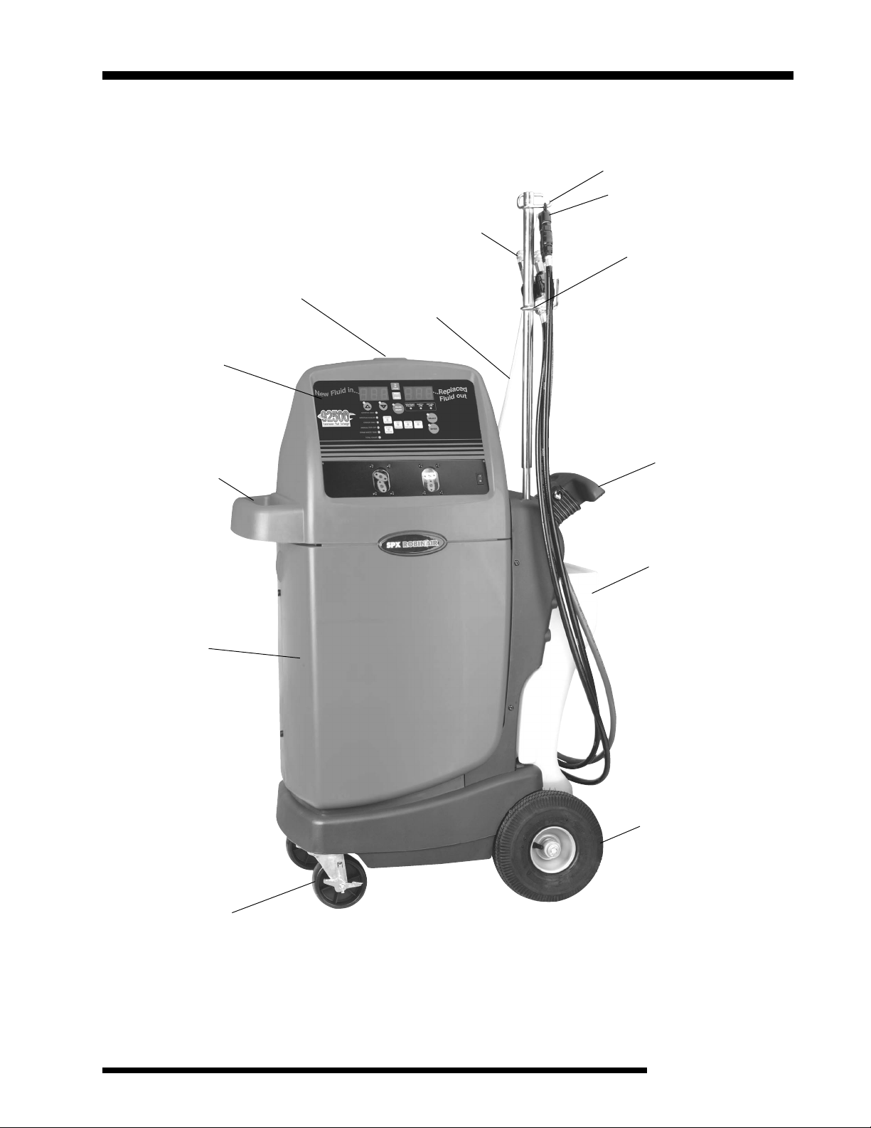
Unit Front View
Control Panel
Shelf for tools and
accessories
Indicator Light
Selector Valve
Assembly
Nylon Hose
Hose Hanger
Dipstick Wand Assembly
Hose Hanger
Built-in Handle
Tank for new oil
Polypropylene
Cabinet for
durability and light
weight
Locking Casters
Large Wheels for
ease of mobility
Transmission Fluid Exchanger
33
3
33
Page 6
Introduction
Component Identification and Location
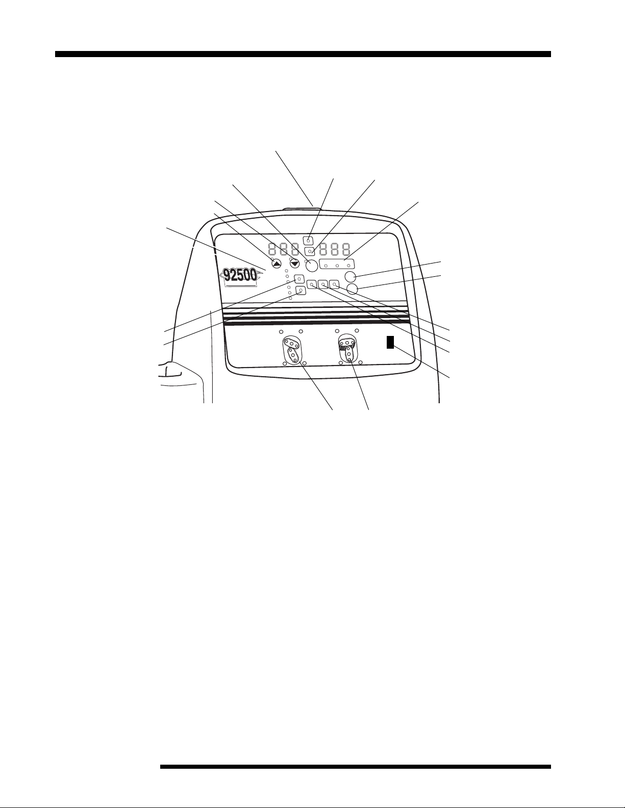
Control Panel
ON/OFF Indicator Light
Pause/Abort
Down
Up
Button
N
e
w
s
s
i
m
s
n
a
r
T
n
i
.
.
d
i
.
u
l
F
DIPSTICK ONLY
START
DIPSTICK/COOLER
COOLER ONLY
r
e
g
n
a
h
c
x
E
d
i
u
l
F
n
o
i
MANUAL/TOP-OFF
DRAIN WASTE TANK
TOTAL COUNT
SERVICE
START
ENGINE
SERVICE
END
Arrow Buttons:
Mode LED Indicators:
Dipstick Only
Dipstick/Cooler
Cooler Only
Manual/Top-Off
Drain Waste Tank
Total Count
Start Service LED
Start Engine LED
continued
Transfer LEDs:
To Trans From Trans
d
e
c
.
a
.
l
.
p
R
e
u
o
t
d
i
u
l
F
RETURN
REVERSED
SUPPLY
LINE
LINE
POLARITY
SELECT
FINISH
CHECK
LEVEL
ENTER
I
O
Light Indicators:
Reversed Polarity
Supply Line
Return Line
Select Button
Enter Button
Finish LED
Check Trans Level LED
End Service LED
ON/OFF
Switch
Transfer Indicators: ATF In ATF Out
New Fluid In — Displays amount of fluid added.
Replaced Fluid Out — Displays amount of fluid extracted.
UP/DOWN Arrows — Adjusts amount of fluid in or out.
Pause/Abort — Pauses or aborts a transfer.
Error Message Indicators — Displays error message.
Mode Indicators — Identifies procedures available.
Select Button — Selects the desired mode or procedure.
Enter Button — Accepts mode selected and starts the ATF exchange.
Display Screens — Displays operational or error information.
Transfer Indicators and LEDs — Indicates the transfer that is presently
taking place.
ON/OFF Power Switch — Turns the unit on.
44
4
44
© 2004 SPX Corporation
Page 7
Initial Setup
Accessory Kit
Unpack Accessory Kit located inside the rear door
of unit. Accessory Kit includes: Adapter set,
warranty card, and hose hanger bracket.
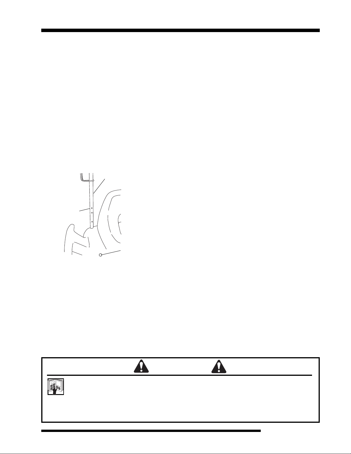
Attach Hose Hanger Bracket
1.
Drop tube all the way down over existing tube
on unit.
2. Rotate to align holes.
3. Insert screw into the middle hole.
Hose Hanger Bracket
Align holes
Application Notes
Ford Taurus with a 3.0 liter V6 requires the
removal of the vent cap located behind the
shifter linkage on top of transmission before
service. This will minimize “overfilling” due to
lack of headroom in the transmission housing.
Low pressure transmissions require the
transmission be left in neutral with the parking
brake secured during the “dynamic” (engine
running) phase of the ATF service.
Import vehicles, with small dipstick tube
openings, require the 529740 flexible nylon
hose, which has a smaller blue section at the
end, in place of the 529734 hose.
Helpful Tips
To avoid oil spillage, turn unit on before removing
the flexible nylon hose from its storage area.
Press the Pause/Abort once to pause an opera-
Nylon Hose
Storage
Registering the Unit
To validate the warranty provided by SPX
ROBINAIR, complete the warranty card included
in the accessory kit, and mail it within ten days
from the date of purchase.
tion; press ENTER to continue the operation.
Press and hold the Pause/Abort button to
discontinue an operation and to reset the unit.
For the quickest and most accurate exchange,
ensure transmission is warmed to normal
operating temperatures.
IMPORTANT: To prevent damage to the
vehicle, ensure all hoses are correctly
connected before transferring fluid.
WARNING
This manual contains important procedures concerning the setup, operation, and
maintenance of the unit. Study and follow all warnings at the beginning of this manual. Do
not operate the unit until you have read and understand the contents of this manual. If you
do not understand any of the contents of this manual, notify your supervisor. If the operator
cannot read English, all instructions and safety precautions must be read and discussed in the
operator’s native language.
Transmission Fluid Exchanger
55
5
55
Page 8

Operating Procedures
Dipstick Only Mode
The Dipstick Only mode transfers used ATF and
new ATF through the transmission’s dipstick
tube by running a hose into the transmission
fluid pan, emptying it of its contents, and then
with engine running, adding ATF. ATF is then
subtracted until a user specified amount of new
ATF has been added.
Note: Confirm vehicle and transmission are at
operating temperature before initiating service.
Power Up
1. Connect the power cord to a 12V DC
battery: red to the positive post and black to
the negative post.
2. Turn the unit on. The
lights if the power is connected incorrectly.
The unit self-tests: The buzzer sounds, all
LEDS and displays light, the flexible nylon
hose evacuates ATF, and the software
version displays.
3. Remove dipstick from the transmission tube.
4. Insert the unit’s flexible nylon hose into the
transmission dipstick tube as far as possible
to reach the bottom of the oil pan. The
Dipstick Only, Dipstick/Cooler, Cooler Only,
Manual/Top-Off, Drain Waste Tank, and
Total Count
button LEDs are still lit and flashing.
5. Press the SELECT button until the
Only
LED is lit.
6. Pause until the ENTER LED lights and
flashes (about one second).
7. Press ENTER to confirm the selection. The
left display (
default quantity in quarts of new ATF to be
run into the system).
8. Use the arrow keys to select the amount of
quarts to be transferred. (12 quarts is the
default; minimum is 6 quarts, maximum is 32
quarts.)
indicators, and the
New Fluid In
Reversed Polarity
SELECT
Dipstick
) reads 12 (the
LED
9. Press ENTER to confirm the quantity
displayed. The alarm sounds, and the
Service
and ENTER LEDs flash.
Start
Start Service
1. With the vehicle engine off, press ENTER to
start the ATF exchange. The following takes
place:
a. The unit purges its internal fluid lines.
b. Used ATF is then extracted from the
transmission pan until empty.
c. The cumulative volume extracted
on the
d. Through the nylon transfer hose, the unit
pumps back into the transmission fluid pan
the same volume of new ATF that appears
on the
e. The volume of new fluid yet to be pumped
into the transmission pan is shown on
Fluid In
“Power Up” step 8 minus the amount
transferred in “Start Service” step 1d.)
f. The
2. Start the vehicle’s engine to circulate the new
ATF through the transmission system (torque
converter and cooler lines).
3. Press ENTER to confirm the engine is
running.
The exchanger extracts one quart of diluted ATF
and returns one quart of new ATF through the
hose and back into the transmission fluid pan.
The
respectively the amount of fluid extracted and
the amount of new fluid to be added. This
recycling continues until the selection made in
step 8 under “Power Up” is met (i.e., using the
12 quart default,
and
New Fluid In
Replace Fluid Out
Replace Fluid Out
display. (The amount designated in
Start Engine
Replace Fluid Out
Replace Fluid Out
will be 0).
display.
display.
and ENTER LEDs flash.
and
New Fluid In
appears
New
displays
will be 12
66
6
66
© 2004 SPX Corporation
Page 9

Operating Procedures
Dipstick Only Mode
When the selection in step 8 is met, the buzzer
sounds and the
light.
4. Press ENTER to confirm that the correct
amount of ATF has been replaced.
Trans Level
End Service
LED lights.
continued
and ENTER LEDs
Check
Check the ATF Level in the Pan
1. Remove the flexible nylon hose.
2. Insert the dipstick.
3. Remove dipstick to check level of fluid.
If the fluid level needs to be adjusted, continue
on to “Adjust the ATF Level.” If the level is
satisfactory, go to step 4 under “Adjust the ATF
Level.”
Adjust the ATF Level
a. If the level is too low, select
LED. Press ENTER. Press the up arrow key
to select how much fluid to add (each press
indicates one-tenth of a quart).
b. If the level is too high, select
LED. Press ENTER. Press the up arrow key
to select how much fluid to take out (each
press indicates one-tenth of a quart).
3. When transfer is complete, go to “Check the
ATF Level in the Pan.”
4. If the level is satisfactory, press SELECT
until
Finish
LED lights.
a. Wait for one second.
b. Press ENTER to confirm the function.
c. Press ENTER again.
The display reads SR FIN, indicating the service
is finished.
To Trans
From Trans
1. Place the flexible nylon hose in the dipstick
tube.
2. Press ENTER. The
and
Finish
LEDs light.
To Trans, From Trans
Transmission Fluid Exchanger
77
7
77
Page 10

Operating Procedures
Dipstick/Cooler Mode
Initially transfers used ATF and new ATF
through the transmission’s dipstick tube. Then
with the engine running, new ATF is pumped
into the transmission through the dipstick tube,
while the old ATF is evacuated through the
cooler lines. This mode provides the quickest
transfer of used and new ATF.
Note: Confirm vehicle and transmission are at
operating temperature before initiating service.
Identify Cooler Lines
1. Disconnect cooler lines, and attach adapters
to the input and output connectors. These
adapters may be open hoses and/or snap or
threaded fittings.
Note: To minimize the total time of the ATF
service, this step may be performed during
the “static” (engine not running) phase, when
the used ATF in the transmission pan is
being exchanged with the new ATF.
6. Insert the unit’s flexible nylon hose into the
transmission dipstick tube as far as possible
to reach the bottom of the transmission fluid
pan. The
Cooler Only, Manual/Top-Off, Drain Waste
Tank, Total Count
SELECT button LEDs are still lit and
flashing.
7. Press the SELECT button until only the
Dipstick/Cooler
8. Pause until the ENTER LED lights and
flashes (about one second).
9. Press ENTER to confirm the selection. The
left display (
default quantity in
run into the system).
10. Use the arrow keys to select the amount of
quarts to be transferred. (12 quarts is the
default; minimum is 6 quarts, maximum is 32
quarts.)
Dipstick Only, Dipstick/Cooler,
indicators, and the
LED is lit.
New Fluid In
quarts of new ATF to be
) reads 12 (the
Power Up
1. Connect the power cord to a 12V DC
battery: red to the positive post and black to
the negative post.
2. Turn the unit on. The
lights if the power is connected incorrectly.
The unit self-tests: The buzzer sounds, all
LEDS and displays light and flash, the
flexible nylon hose evacuates ATF, and the
software version displays.
3. Attach the adapters to the unit’s cooler line
selector valve assembly.
can be connected to either coupler
4. Confirm connections are secure.
5. Remove the dipstick from the transmission
tube.
Reversed Polarity
Note: The adapters
.
LED
11. Press ENTER to confirm the quantity
displayed. The alarm sounds and the
Service
and ENTER LEDs flash.
Start
Start Service
1. Press ENTER to start the ATF exchange.
The following takes place:
a. The unit purges its internal fluid lines.
b.
Used ATF is then extracted from the
transmission fluid pan until empty.
c. The cumulative volume extracted appears
on the
d. Through the flexible nylon hose, the unit
pumps back into the transmission fluid pan
the same volume of new ATF that appears
on the
Replace Fluid Out
Replace Fluid Out
display.
display.
88
8
88
© 2004 SPX Corporation
Page 11

Operating Procedures
Dipstick/Cooler Mode
e. The volume of new fluid yet to be pumped
into the transmission pan is shown on
Fluid In
“Power Up” step 10 minus the amount
transferred in “Start Service” step 1d).
f. The
2. Start the vehicle’s engine to circulate the
ATF through the transmission system (torque
converter and cooler lines).
3. Press ENTER to confirm the engine is
running.
The unit extracts used ATF from the cooler lines
and returns new ATF through the nylon transfer
hose and back into the transmission fluid pan.
The
Replace Fluid Out
displays respectively the amount of ATF
extracted and the amount of new ATF added.
This recycling continues until the selection made
in step 10 under “Power Up” is met.
When the preset amount is met, the buzzer
sounds and the
light.
4. Press ENTER to confirm that the correct
amount of ATF has been replaced.
Trans Level
display (the amount designated in
Start Engine
End Service
LED lights.
and ENTER LEDs flash.
and
continued
New
New Fluid In
and ENTER LEDs
Check
Check the ATF Level in the Pan
1. Remove the flexible nylon transfer hose.
Adjust the ATF Level
1. Place the flexible nylon hose in the dipstick
tube.
Note: An alternative method is to disconnect
the red hose from the dipstick wand
assembly, and connect it to the selector
valve assembly.
Adapters
Red Hose
Selector Valve
Assembly
2. Press ENTER. The
and
Finish
LEDs light.
a. If the level is too low, select
LED. Press ENTER. Press the up arrow key
to select how much fluid to add (each press
indicates one-tenth of a quart).
b. If the level is too high, select
LED. Press ENTER. Press the up arrow key
to select how much fluid to take out (each
press indicates one-tenth of a quart).
3. When transfer is complete, go to “Check the
ATF Level in the Pan.”
4. If the level is satisfactory, press SELECT
until
Finish
LED lights.
To Trans, From Trans
To Trans
From Trans
2. Insert the dipstick.
3. Remove the dipstick to check fluid level.
If the fluid level needs to be adjusted, continue
on to “Adjust the ATF Level.” If the level is
satisfactory, go to step 4 under “Adjust the ATF
Level.”
Transmission Fluid Exchanger
a. Wait for one second.
b. Press ENTER to confirm the function.
c. Press ENTER again.
The display reads SR FIN, indicating the service
is finished.
99
9
99
Page 12

Operating Procedures
Cooler Only Mode
Transfers used ATF and new ATF through the
cooler lines.
Note: Confirm vehicle and transmission are at
operating temperature before initiating service.
Identify Cooler Lines
1. Disconnect cooler lines, and attach adapters
to the input and output connectors.
Power Up
1. Connect the power cord to a 12V DC
battery: red to the positive post and black to
the negative post.
2. Turn the unit on. The
lights if the power is connected incorrectly.
The unit self-tests: The buzzer sounds, all
LEDS and displays light and flash, the
dipstick tube holder evacuates ATF, and the
software version displays.
Reversed Polarity
LED
8. Press ENTER to confirm the selection. The
left (
New Fluid In
default quantity in
run into the system).
9. Use the arrow keys to select the amount of
quarts to be transferred. (12 quarts is the
default; minimum is 6 quarts, maximum is 32
quarts.)
10. Press ENTER to confirm the quantity
displayed. The alarm sounds and the
Engine
11. Start the vehicle’s engine.
and ENTER LEDs flash.
) display reads 12 (the
quarts of new ATF to be
Start
Start Service
1. Press ENTER to start the ATF exchange.
The following takes place:
a. The unit extracts used ATF from one of
the cooler lines.
3. Attach the adapters to the unit’s cooler line
selector valve assembly.
can be connected to either coupler.
4. Disconnect the red hose from the dipstick
wand assembly, and connect it to the
selector valve assembly.
Adapters
Selector Valve
Assembly
5. Confirm connections are secure.
6. Press the SELECT button until only the
Cooler Only
7. Pause until the ENTER LED lights and
flashes (about one second).
LED is lit and flashing.
Note: The adapters
Red Hose
b.
The amount of ATF extracted appears on
the
Replaced Fluid Out
selected in
were extracted in step 1a above,
Fluid Out
c. The unit replaces the ATF taken out with
new ATF through the other cooler line.
This recycling continues until the selection in
step 9 under “Power Up” is met. When the
selection is met, the buzzer sounds and the
Service
2. Press ENTER to confirm that the correct
and ENTER LEDs light.
amount of oil has been replaced.
Trans Level
“Power Up”
will display 9).
LED lights.
display (i.e., if 12 was
step 9, and 3 quarts
Replaced
Check
End
1010
10
1010
© 2004 SPX Corporation
Page 13

Operating Procedures
Cooler Only Mode
continued
Check the ATF Level in the Pan
1. Remove the dipstick to check level of fluid in
transmission fluid pan. If the vehicle does not
have a dipstick, refer to the vehicle’s service
manual for the method required to check the
fluid level.
If the fluid level needs to be adjusted, continue
on to “Adjust the ATF Level.” If the level is
satisfactory, go to step 4 under “Adjust the ATF
Level.”
Adjust the ATF Level
1. Press ENTER. The
and
Finish
LEDs light.
a. If the level is too low, select
LED. Press ENTER. Press the up arrow key
to select how much fluid to add (each press
indicates one-tenth of a quart).
b. If the level is too high, select
LED. Press ENTER. Press the up arrow key
to select how much fluid to take out (each
press indicates one-tenth of a quart).
2. When transfer is complete, go to “Check the
ATF Level in the Pan.”
3. If the level is satisfactory, press SELECT
until
Finish
LED lights.
To Trans, From Trans
To Trans
From Trans
Manual/Top-Off Mode
Transfers used ATF and new ATF through the
transmission’s dipstick tube. This mode is
commonly used when the transmission fluid pan
needs to be removed (to change gaskets or
replace a filter). When using another mode, this
mode is required to top off the ATF fluid level.
Note: Confirm vehicle and transmission are at
operating temperature before initiating service.
Power Up
1. Connect the power cord to a 12V DC
battery: red to the positive post and black to
the negative post.
2. Remove the dipstick from the transmission
noting ATF level, which will determine
whether additional ATF needs to be added
or withdrawn.
3. Turn the unit on. The
lights if the power is connected incorrectly.
The unit self-tests: The buzzer sounds, all
LEDS and displays light and flash, the
flexible nylon hose evacuates ATF, and the
software version displays.
4. Insert the unit’s flexible nylon transfer hose
into the transmission dipstick tube as far as
possible to reach the bottom of the oil pan.
Reversed Polarity
LED
a. Wait for one second.
b. Press ENTER to confirm the function.
c. Press ENTER again.
The display reads SR FIN, indicating the service
is finished.
Transmission Fluid Exchanger
5. Press the SELECT button until only the
Manual/Top-Off
6. Pause until the ENTER LED lights and
flashes (about one second).
7. Press ENTER to confirm the selection. The
Check Trans Level, To Trans,
Trans
display.
LEDs light
LED is lit and flashing.
and
From
. Drn Pan
appears on the
1111
11
1111
Page 14

Operating Procedures
Manual/Top-Off Mode
continued
Adjust the ATF Level
1. In step 2 under “Power Up,” the ATF level
was determined noting whether ATF needed
to be added, subtracted, or it was satisfactory.
a.
If the level is too low, select
(1) Press Enter.
(2) Press the arrow key to select how
much fluid to add (each press indicates onetenth of a quart).
(3) Pause after the correct volume is
selected. The ENTER key lights and flashes.
(4) Press ENTER to start the service.
b. If the level is too high, select
Trans
LED.
(1) Press Enter.
(2) Press the arrow key to select how
much fluid to take out (each press indicates
one-tenth of a quart).
(3) Pause after the correct volume is
selected. The ENTER key lights and flashes.
(4) Press ENTER again to start the
service.
c. If the transmission fluid pan needs to
be removed, press SELECT until
appears on the display.
To Trans
From
Drn Pan
LED.
2. Press ENTER. The amount removed will
display on the
3. Adjust the
Replaced Fluid Out
4. Press ENTER.
New Fluid In
Replaced Fluid Out
display to match the
display.
display.
Drain Waste Tank
Transfer used ATF from the internal waste tank
to an external waste ATF reservoir.
Power Up
1. Connect the power cord to a 12V DC
battery: red to the positive post and black to
the negative post.
2. Ensure the unit’s hoses are disconnected
from the vehicle.
3. Turn the unit on. The
lights if the power is connected incorrectly.
The unit self-tests: The buzzer sounds, all
LEDS and displays light and flash, the
flexible nylon hose evacuates ATF, and the
software version displays.
4. Disconnect the red hose from the wand
assembly. Connect the drain waste adapter
(#546763) to the red hose, and place into an
external waste ATF reservoir.
Reversed Polarity
LED
(1) Pause until ENTER LED lights (about
one second).
(2) Press ENTER to confirm the function.
(3) Press ENTER again to start draining
the pan. The unit will stop when pan is empty.
Refill Transmission Fluid Pan
To refill the transmission fluid pan,
1. Press SELECT until the
1212
12
1212
To Trans
LED is lit.
Start Service
1. Press the SELECT button until only the
Drain Waste Tank
2. Pause until the ENTER LED lights and
flashes (about one second).
3. Press ENTER to confirm the selection. The
display reads DRN (XXX), which is the
amount left to be drained.
When the waste tank is drained, the display
reads SR FIN, indicating service is finished.
LED is lit and flashing.
© 2004 SPX Corporation
Page 15

Operating Procedures
Total Count
Displays the number of ATF exchanges
performed.
Power Up
1. Connect the power cord to a 12V DC
battery: red to the positive post and black to
the negative post.
2. Turn the unit on. The
lights if the power is connected incorrectly.
The unit self-tests: The buzzer sounds, all
LEDS and displays light and flash, the
flexible nylon hose evacuates ATF, and the
software version displays.
Start Service
1. Press the SELECT button until only the
Count
LED is lit and flashing.
2. Pause until the ENTER LED lights and
flashes (about one second).
Reversed Polarity
LED
Total
Changing Transmission
Fluid Types
To change transmission fluid type in a new tank:
1. Connect the power cord to a 12V DC
battery: red to the positive post and black to
the negative post.
2. Insert the flexible nylon hose into a clean
ATF container.
3. Press the SELECT button until
Off
LED lights.
4. Press ENTER.
5. Press the SELECT button until
LED
lights.
6. Press ENTER.
7. Press the UP arrow key until display reads
an amount more than what is in the new
tank.
Manual/Top-
To Trans
3. Press ENTER to confirm the selection.
The total number of services performed is
displayed; the
4. Press ENTER to return to mode selection
after noting the total number of services.
Finish
LED flashes.
8. Press ENTER. The unit will pump ATF from
the new tank into the clean ATF container.
9. Turn the unit off when completed. The unit
will clear the lines when it is restarted.
Transmission Fluid Exchanger
1313
13
1313
Page 16

Error Messages
ER FLO — Return Line is lit. No oil is returning.
ER FLO — Supply Line is lit. Check new oil reservoir.
Reversed Polarity is lit. Check battery connections.
Maintenance
•
•
Check the flexible nylon hose for cuts and/or kinks.
Filter screens may need to be cleaned. Locate the filter screens inside the
unit; clean if necessary.
Cabinet can be kept clean by wiping it down with a clean cloth.
•
Check wires for cuts and/or damage.
•
1414
14
1414
© 2004 SPX Corporation
Page 17

Replacement Adapters
529567 - Complete adapters kit. All replacement adapters described
below are included in the kit.
Part Order No. Description Application
Original No.
529568 1/4" (M6) Barb Assembly General
6304-06
529569 5/16" (M8) Barb Assembly General
6304-08
529570 3/8" (M10) Barb Assembly General
6304-10
529571 1/4" (M6) Open End Hose General
6303-06
529572 5/16" (M8) Open End Hose General
6303-08
529573 3/8" (M10) Open End Hose General
6303-10
529574 1/2" (M13) Open End Hose General
6303-12
529575 5/16" x 90 Internal Domestic
6306-03
529576 3/8" External x 5/16" External Domestic
6310-10
and Import
529577 3/8" Internal Snap Lock Domestic
6306-05
Qty. 2
529578 1/2" External Snap Lock Chrysler
6310-12
529579 1/2" External Angle Step GM
6312-01
Transmission Fluid Exchanger
529580 3/8" External Angle Step GM
6311-01
1515
15
1515
Page 18

Replacement Adapters contd.
Part Order No. Description Application
Original No.
529581 5/16" Flare, 1/2" - 20 Assembly Domestic
6318-05
529582 1/2" - 20 External (Long End SAE) Ford
6308-04
529583 1/2" - 20 Internal x SAE 45 Degrees Domestic
6313-01
529584 5/8" - 18 Internal x SAE IN Ford
6307-04
529585 3/8" Flare, 5/8" - 18 Assembly Domestic
6318-06
and Import
and Import
and Import
529586 5/8" - 18 Internal x SAE 45 Degrees Domestic
6301-01
and Import
529587 M14 Banjo Fitting Import
6308-14
(2 fittings included in 529567 Kit)
529588 M16 Internal Swivel Import
6310-16
529589 5/8" - 18 Internal x 45 Degrees Domestic
6302-02
and Import
529590 S/25 x 1/4" NPTM Plug Domestic
2025-13
(2 plugs included in 529567 Kit)
529591 S/25 x 3/8" NPTM Plug Domestic
2025-33
1616
16
1616
© 2004 SPX Corporation
Page 19

Replacement Adapters contd.
Part Order No. Description Application
Original No.
529592 1/2" to 29/32" x 5/16" Band Clamp General
2102-07
529593 M14 Banjo Bolt Long Import
6007-14
529594 M14 Cap Nut Import
1419-98
529595 M14 Copper Washer Import
1602-14
529596 S/25 x 3/8" NPTF Plug Domestic
2025-32
529597 1/2" x 20 Internal Inverted Domestic
6308-02
(3 clamps included in 529567 Kit)
(3 washers included in 529567 Kit)
and Import
529598 1/2" x 20 Internal SAE Inverted Ford
6308-03
529599 5/8" x 18 Ford
6307-03
529600 1/2" x 20 External x 45 Degrees Domestic
6313-02
and Import
529601 S/25 x 1/4" NPTF Plug Domestic
2025-12
529734 75" x 5/16" OD Dipstick Tube Adapter Assembly
6300-00-75
with compression fitting connection
547222 75" x 5/16" OD Dipstick Tube Adapter Assembly
6300-00-75
with push-to-connect fitting connection
529740 42" x 1/4" OD Dipstick Tube Adapter
6300-00-42
with compression fitting connection
547223 42" x 1/4" OD Dipstick Tube Adapter
6300-00-42
with push-to-connect fitting connection
Transmission Fluid Exchanger
1717
17
1717
Page 20

Replacement Adapters contd.
Part Order No. Description Application
Original No.
546763 S/48 x 9" Hose - Drain Hose Assy. Drain
2030-31
546764 1/2" Female Snap Lock Domestic
6306-08
546765 3/8" Male Snap Lock Ford
6319-06
546766 1/2" Push-on Barb Ford
6304-12
Waste
Tank
1818
18
1818
© 2004 SPX Corporation
Page 21

Replacement Parts
Illustration Part Number Description
92501 Pump Assembly Replacement
92501RBK Pump Head
90516 New Oil Reservoir Cap
B
A
92509
(A in illustration) 2 Required
92510 Directional Valve Assembly
(Entire assembly shown at left)
92511 Quick Disconnect Plug, S/48 x 1/4" External NPT
(B in illustration)
92513 Pressure Hose (Red; 92" x 3/8" Barb Assembly)
92514 Recovery Hose (Black; 92" x 3/8" Barb Assembly)
92515 Cooler Hose (Black; 92" x 3/8" Barb Assembly)
92516 Power Cord Assembly
Quick Disconnect Coupler, S/25 x 1/4" Internal NPT
Transmission Fluid Exchanger
92517 Quick Disconnect Coupler,
(A in illustration)
92518 Quick Disconnect Plug,
(D in illustration)
92521 Replacement Wand Assembly
(Entire assembly shown at left)
S/48 x 3/8" External NPT
S/48 x 3/8" External NPT
1919
19
1919
Page 22

Limited Warranty
Robinair Limited Warranty Statement
Rev. November 1, 2005
This product is warranted to be free from defects in workmanship, materials, and components for a
period of one year from date of purchase. All parts and labor required to repair defective products
covered under the warranty will be at no charge. The following restrictions apply:
1. The limited warranty applies to the original purchaser only.
2. The warranty applies to the product in normal usage situations only, as described in the Operating
Manual. The product must be serviced and maintained as specified.
3. If the product fails, it will be repaired or replaced at the option of the manufacturer.
4. Transportation charges for warranty service will be reimbursed by the factory upon verification of
the warranty claim and submission of a freight bill for normal ground service. Approval from the
manufacturer must be obtained prior to shipping to an authorized service center.
5. Warranty service claims are subject to authorized inspection for product defect(s).
6. The manufacturer shall not be responsible for any additional costs associated with a product
failure including, but not limited to, loss of work time, loss of refrigerant, cross-contamination of
refrigerant, and unauthorized shipping and/or labor charges.
7. All warranty service claims must be made within the specified warranty period. Proof-of-purchase date must be supplied to the manufacturer.
This Limited Warranty does NOT apply if:
• The product, or product part, is broken by accident.
• The product is misused, tampered with, or modified.
© 2004 SPX Corporation Transmission Fluid Exchanger
Page 23

Visit our web site at
www.robinair.com
or
%
Call our Toll-Free
Technical Support Line at
800-822-5561
in the continental U.S. or Canada.
In all other locations, contact your local distributor. To help us serve
you better, be prepared to provide the model number, serial number,
and date of purchase of your unit.
To validate your warranty, complete the warranty card attached to your
unit, and return it within ten days from date of purchase.
NATIONWIDE NETWORK OF AUTHORIZED SERVICE CENTERS
If your unit needs repair or replacement parts, contact the service
center in your area. For help in locating a service center, call the
toll-free technical support line.
Due to ongoing product improvements,
we reserve the right to change design,
specifications, and materials without notice.
®
SPX Corporation
655 Eisenhower Drive
Owatonna, MN 55060-0995 USA
Technical Services: 1-800-822-5561
Fax: 1-412-690-2001
Customer Service: 1-800-533-6127
Fax: 1-800-322-2890
Web Site: www.robinair.com
526233 Rev. C (December 20, 2007) 92500 Transmission Fluid Exchanger © 2004 SPX Corporation
 Loading...