

Page 1
40134A, 40152, 40153, 41600, 41700 SERIES
MANIFOLD OPERATING INSTRUCTIONS
WARNING
Always wear safety goggles when working with refrigerants. Contact with refrigerant can cause eye injury.
Disconnect hoses with extreme caution!
Pressurized refrigerant may be present in
hoses. Always point hoses away from you
and anyone nearby.
Your manifold is designed so that all three lower fittings are
connected to each other by internal passages. Separate passages
from the low and high side fittings to their respective gauges
give you pressure and vacuum readings whether the handwheels
are open or closed. For your convenience and safety, handwheels
and gauges are color-coded with the blue compound gauge on
the left or low side, and the red pressure gauge on the high or
right side.
Connecting Field Service Couplers (40134A)
Field service couplers are provided to access the vehicle’s
service ports. The service coupler should be in the closed
position before connecting to the external fitting on the vehicle.
1. To close, turn the handle counterclockwise until finger
tight.
2. Place the service coupler on the external fitting.
3. Push in on the handle of the service coupler with your
thumb, while pulling up on the sleeve, until it bottoms on
the external fitting; then release. Check to see if it is
correctly seated by pulling up on the service coupler.
4. For maximum flow, turn the handle clockwise until it
stops.
Diagnosing System Operation
1. Connect the blue low side hose to the A/C system’s low
side service port. Connect the red high side hose to the
A/C system’s high side service port.
2. With the manifold handwheels closed, read the pressures
on the gauge face.
3. Use the temperature/pressure chart stored on the back of
the gauge holster to find the corresponding temperature
for the refrigerant in the system (41600, 41700).
4. Compare these pressures and temperatures to the A/C
system manufacturer’s specifications for proper operation.
5. If the system is within the correct operating guidelines,
disconnect the manifold hoses from the system. If
repairs are necessary, follow the steps for recovering,
evacuating, and recharging the system.
Recovering Refrigerant
Note: According to federal law, refrigerant should not be
exhausted to the atmosphere.
1. Be sure the blue low side hose is connected to the A/C
system’s low side service port and that the red high side
hose is connected to the A/C system’s high side service
port.
Note: Typically, the yellow center hose is connected to the
inlet of the recovery unit.
2. Follow the instructions provided with the recovery unit
for proper recovery of refrigerant from the A/C system.
Evacuating and Charging a Refrigerant System
1. Connect the blue low side hose to the A/C system’s low
side service port. Connect the red high side hose to the
A/C system’s high side service port.
2. Check the manifold gauge pressure reading to be sure
the A/C system has been recovered properly. If it is not,
follow steps under “Recovering Refrigerant.” If it is,
connect the center yellow charging hose to a vacuum
pump.
3. Open the high and low side handwheels and start the
vacuum pump.
4. After evacuating the system according to the manufacturer’s specifications, close both the high and low
side handwheels and turn off the vacuum pump.
5. Disconnect the yellow hose from the vacuum pump and
connect it to the refrigerant supply.
6. Slightly open the refrigerant supply valve. Purge air
from the yellow charging hose at the manifold, then
close the supply valve.
7. You can now charge the A/C system according to the
manufacturer’s specifications.
• If the system specifications call for charging on the high
side, close the manifold’s blue low side handwheel, open
the refrigerant supply valve and open the manifold’s red
high side handwheel. After dispensing the proper
amount of refrigerant, close the manifold’s red high side
handwheel and close the refrigerant supply valve.
• If the system specifications call for charging on the low
side, close the manifold’s red high side handwheel, open
the refrigerant supply valve and open the manifold’s
blue low side handwheel. After dispensing the proper
amount of refrigerant, close the manifold’s blue low side
handwheel and close the refrigerant supply valve.
(continued)
Page 2
8. When you have charged the system, close both manifold
handwheels. Let the compressor run and check the
manifold’s gauge pressure readings to be sure the
system is operating properly. If it is not, adjust the
system as necessary. To disconnect the manifold when
the system is operating correctly, see the steps below for
your specific manifold.
• For the 40134A manifold, first close the high side
coupler valve. Open the low side coupler valve. Then
disconnect the red high side hose from the A/C system.
After disconnecting, go to step 9.
• For all other manifolds, close both handwheels on the
manifold. Carefully remove the charging hoses from the
system. Charging is now complete.
9. Restart the A/C system, then open both manifold
handwheels. Refrigerant from both hoses will be drawn
quickly into the A/C system through the blue low side
hose.
10. When both gauges show the lowest operating pressure
recommended by the manufacturer, close the low side
valve and turn off the A/C system.
11. Close the low side coupler valve and disconnect the low
side hose from the A/C system.
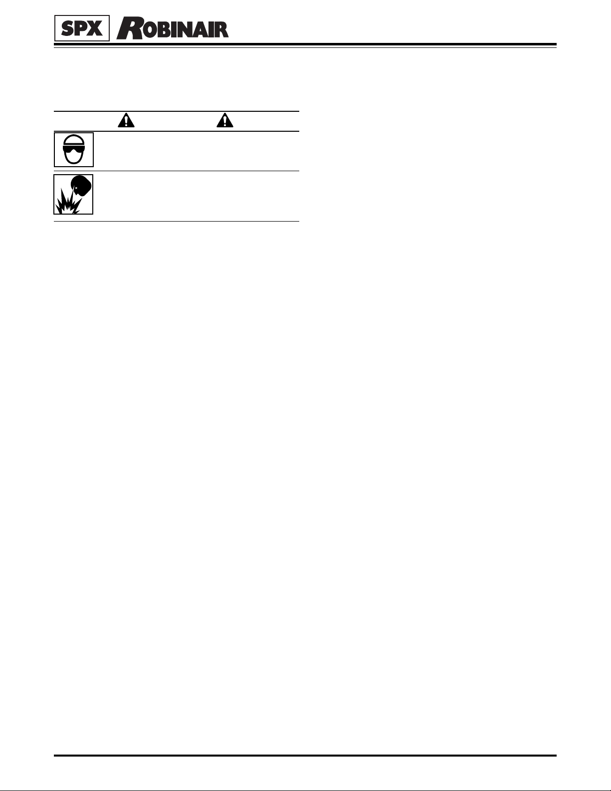
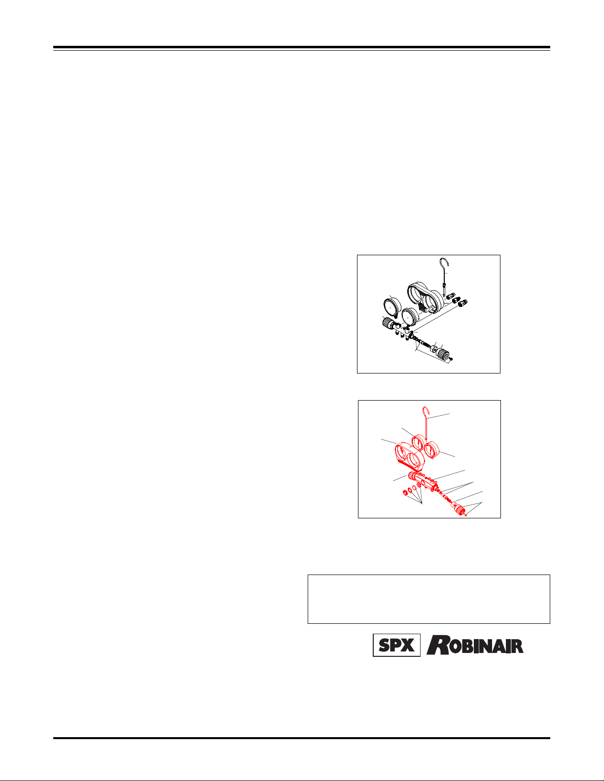
REPLACEMENT PARTS LIST
MAINTAINING YOUR MANIFOLD
To keep your manifold in top operating condition:
• Periodically replace O-rings and valve seats.
• Be sure to lubricate O-rings with Robinair’s High
Vacuum Grease (part number 13033).
WARRANTY COVERAGE
Your manifold is covered by our One Year Limited Warranty. We guarantee your manifold to be free from defects in
material and workmanship under normal use and service for
one year from the date of sale. See your distributor for details.
4
3
1
9
6
5
2
8
7
1 Blue Barrel Handwheel Set 41698
2 Manifold Bar without Gauges (41600) 41694
(41700) 19690
3 Compound Gauge, blue case, °F
40134a, 40152, 40153, 41600, 41700 Series 11794
3 Compound Gauge, blue case, °C
40151, 41612, 42134A 11797
4 Hanging Hook 41697
5 Pressure Gauge, red case, °F
40134a, 40152, 40153, 41600, 41700 Series 11795
5 Pressure Gauge, red case, °C
40151, 41612, 42134A 11798
6 Flexible Holster (41600) 41691
Flexible Holster (41700) 19691
7 Red Barrel Handwheel Set 41698
8 Hex Nut 41616
9 Complete Stem Assembly,
2 required (41600 includes seat and O-rings) 41617
41700 19695
10 Sight Glass Assembly (41700) 19693
High Pressure Gauges for Model 41670:
Compound Gauge, psi 41675
Pressure Gauge, psi 41676
40134A, 41600
4
4
3
6
5
5
2
1
9
8
7
10
41700
Because of ongoing product improvements, we reserve the right
to change design, specifications, and materials without notice.
INST 0740
For more information call toll-free
1-800-822-5561 in the continental U.S. and
Canada. In all other locations, contact your local
distributor.
SPX Corporation
655 Eisenhower Drive
Owatonna, MN 55060-0995 USA
Technical Services: 1-800-822-5561
Fax: 1-800-822-7805
Customer Service: 1-800-533-6127
Fax: 1-800-322-2890
Web Site: www.robinair. com
122420 (Rev B, 6/03) Manifold Operating Instructions © SPX Corporation
 Loading...