


RS6110
RS6220
RS6320
352-00057-001 Rev B
USERS MANUAL
Thank you for purchasing a Robertshaw RS6000 programmable thermostat. This user’s manual will guide you through the setup of the RS6110 single stage, the RS6220 two stage and the RS6320 three stage* thermostats. The thermostat should already be mounted and correctly wired. The default settings will enable the thermostat to operate efficiently. Before making any changes to the schedule read the section on Default Settings.
Features
•Pop-Up Wizard
•Automatic changeover
•Circulating Fan
•Worry-Free memory retention
•Easy change battery
•Large back lit display
•Filter change reminder
•Low battery indicator
•Fahrenheit and Celsius displays
•EnergyStar™ compliant
•Dual power
•Adjustable 1st stage temperature differential: 0.5 °F to 3.0 °F (0.5 °C to 1.5 °C)
•Accuracy within ±1 °F
•Universal staging on multi-stage units
•Automatic heating shutdown if temperature exceeds 99 °F (37 °C)
•Keypad security lockout
•4 events per day for heating and cooling
•Individual day scheduling
•User settable Hi and Lo temperature limits
*Three stage heating available for heat pump applications only.
1

Application
The Robertshaw 6000 family of thermostats is designed to control gas, electric, oil, heat pump, and millivolt heating and electric cooling systems. The RS6110 is a single stage thermostat while the RS6220 is a two-stage thermostat. The RS6320 can support three stages of heating and two stages of cooling in heat pump applications.
The RS6000 thermostats can have a schedule programmed for each day.
 IMPORTANT SAFETY INFORMATION WARNING:
•Always turn off power at main fuse or circuit breaker panel before installing, removing, cleaning, or servicing thermostat.
•Read all the information in this manual before installing this thermostat.
•This is a 24V AC low-voltage thermostat. Do not install on voltages higher than 30V AC.
•All wiring must conform to local and national building and electrical codes and ordinances.
•Do not short (jumper) across terminals on the gas valve or at the system control to test installation. This will damage the thermostat and void the warranty.
•Do not connect ground to any terminal in this unit.
•This thermostat is configured with automatic compressor protection to prevent damage because of short cycling or extended power outages. Short cycle protection provides a delay between heating and cooling cycles on heat pumps.
Detailed mounting and wiring instructions are explained in the Installation Manual.
Refer to the Pop-Up Wizard section in the installation manual for a complete list of factory defaults and contractor settings.
Providing Power to the Thermostat
For wiring diagrams refer to the Installation Manual.
The thermostats will operate using 24V AC or two AA batteries. When the two AA batteries are installed the thermostat will continue to run if the 24V AC fails.
2

Installing or Changing the Batteries
To remove the battery compartment gently squeeze the ribbed edges on both sides.
The battery compartment will pull down from the thermostat body and will detach. Install two AA batteries following the polarity as shown inside the compartment. Place compartment back into the thermostat.
When the batteries are low the thermostat will enter a low battery mode.
Low battery mode has two levels.
•LEVEL 1: The low battery icon will be displayed thermostat will continue to operate. Replace the batteries as soon as possible
•LEVEL 2: The low battery icon will flash. If 24V AC is
present the thermostat will continue to operate if the batteries are discharged or removed. If 24V AC is not present the thermostat runs on batteries only and THE SYSTEM WILL NOT OPERATE. Replace batteries immediately.
Replace batteries if leaving thermostat unattended for more than 30 days.
The clock will continue to run for 10 minutes when the batteries are removed.
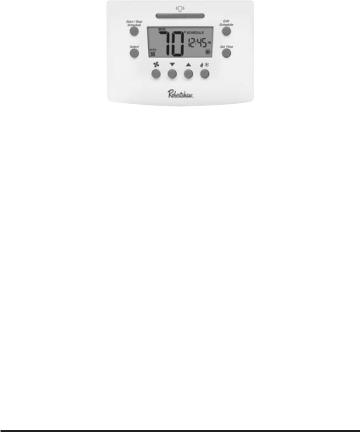
Display Description
The thermostat display will show information that is being used during operation or programming. This illustration shows all of the display’s possibilities with an explanation.
1 |
2 |
|
|
4 |
|
|
|
|
3 |
|
|
|
|
5 |
|
|
|
|
6 |
14 |
|
|
|
|
|
|
|
|
7 |
13 |
|
|
|
|
12 |
11 |
10 |
9 |
8 |
|
||||
|
|
1.Event Names (used for editing schedule).
2.Day is displayed on Idle screen. Also used to display day ranges when editing the schedule (e.g., SAT SUN for weekend).
3.Used with clock to display hold duration (e.g., FOR 2h).
4.On when running a schedule.
5.Used with setpoint.
6.Used along with clock for service reminders (e.g., CHECK HP).
7.Used for time, current setpoint, and some configuration data (e.g., filter hours).
8.HVAC mode and status. Icons blink when active. A is for Auto, 2 is for second stage, E is for emergency.
9.Indicates when security is active.
10.Low battery indicator. 11.Not used.
12.Used for ambient temperature and configuration data (e.g., first stage differential, F or C, etc.).
13.Fan status (rotates when active).
14.Fan mode selected by pressing FAN button.
3

Schedule Settings – Defaults
This thermostat is preprogrammed with a schedule that is recommended by EnergyStar™. The schedule is designed to lower energy costs year-round.
The default schedule settings are:
|
Time |
Cooling °F |
Heating °F |
Morn |
6:00 am |
78 |
70 |
Day |
8:00 am |
85 |
62 |
Eve |
6:00 pm |
78 |
70 |
Nite |
10:00 pm |
82 |
62 |
User Settings – Defaults
During any program changes the display returns back to the operating display if a button has not been pushed in 10 seconds.
The temperature scale is set to Fahrenheit.
Night light is on.
The first stage differential is 1 °F.
The second stage differential (RS6220) is 2 °F.
The second stage delay is 20 minutes.
Third stage delay (RS6320) is 20 minutes.
Auto changeover is enabled.
Auto changeover deadband is 3 °F.
Filter reminder length is off.
Temperature offset is 0 degrees.
The HI heat limit is 90 °F (32 °C).
The LO cool limit is 45 °F (7 °C)
The operation mode is OFF.
The fan setting is Auto.
The keypad has no password protection.
Refer to the pop up wizard section in the installation manual for a complete list of factory defaults and contractor settings.
Emergency Heat
Your system may include Emergency Heat. The RS6220 and RS6320 thermostats have an emergency heat capability for multi stage heat pump systems. To determine if your system is capable of using
emergency heat contact your contractor. Use the 
 button to enter the EMER mode. An E will be displayed with the Heat symbol. This mode is used to bypass the heat pump when it needs servicing or when it cannot keep up with the heat demand.
4
Auto Changeover
Auto changeover is the ability of the thermostat to switch automatically between heating settings and cooling settings. This is useful in Spring and Fall when the days are warm and the nights are cool. In heat mode if the room continues to warm beyond a set threshold the thermostat switches to the cool mode and the associated cooling settings. The reverse is also true.
As the room temperature changes, the thermostat will call for heating or cooling as needed. To prevent the heating and cooling systems from overriding each other, an auto changeover deadband is used.
The deadband is the minimum temperature swing before changing from heating to cooling or vice versa. The larger the deadband the more the room temperature will vary.
Operating the Thermostat
Any setting can be changed when it is flashing by pushing  or
or 
If a button is not pushed for 10 seconds the thermostat returns to operation.
The following buttons can be accessed from the front panel.
START/STOP SCHEDULE: Switches between running a schedule and manual (permanent override). Cancels a temporary override.
EDIT SCHEDULE: Use this button to start editing the schedule. Push repeatedly to move through the selections.
SELECT: Used to select the days that the new schedule will be copied to.
SET TIME: Sequences through the hour, minute and day.
LIGHT BAR: Turns on the display back light for 10 seconds.
FAN: Turns fan to AUTOMATIC, CIRCULATE or ON.
UP ARROW: Raises the setpoint or increases flashing item.
DOWN ARROW: Lowers the setpoint or decreases flashing item.
HEAT/COOL: Toggles through OFF, HEATING, COOLING, and AUTO. If using an RS6220 or RS6320 and configured as HP then emergency heat is also displayed.
5

Setting Time and Day
To adjust the time and day settings press the SET TIME button. The hour will flash. If a button is not pushed in 10 seconds the thermostat returns to operation. To change the settings:
1.Use the  and
and  buttons to change the flashing number.
2.Press the SET TIME button to move through hour, minutes and day of week.
3.Make changes as needed. They will be saved automatically.
NOTE: The thermostat will not correct for Daylight Saving Time.
The thermostat will now function properly using the default schedule.
Changing the Schedule Settings
This thermostat can operate using a single setpoint by overriding the schedules. If you will be using this thermostat for single setpoint operation skip to Overriding the Schedule.
The chart below represents one day’s programming schedule. To make programming your thermostat quicker and easier, recreate the table for each day of the week on a separate piece of paper, and refer to it while programming.
Time |
Cool |
Heat |
Morning
Day
Evening
Nite
Press START/STOP SCHEDULE at any time to exit and save your settings.
Push START/STOP SCHEDULE. The display will show a day flashing at the top. If a button is not pushed in 30 seconds the thermostat returns to normal operation.
Use the  or
or  to change the hour of the start time if desired. Push EDIT SCHEDULE to move to minutes.
Use the  or
or  to change the minutes of the start time if desired. Push EDIT SCHEDULE to move to the heat or cool temperature setting.
Use the  or
or  to change the temperature setpoint. Push EDIT SCHEDULE to move to the other setpoint.
Use  or
or  to change the temperature setpoint.
NOTE: Pressing 
 will switch between cooling and heating setpoints. Pressing Set Time button will switch back to the event time.
NOTE: The heating and cooling setpoints CANNOT be entered as crossed. That is, the cooling setpoint CANNOT BE lower than the heating setpoint.
Push EDIT SCHEDULE and repeat this process for the remaining three settings.
After a single day setting is complete pressing EDIT SCHEDULE will enter into a copy program. To skip the copy program and move to the next day, press EDIT SCHEDULE and repeat the above steps.
6
To begin selecting days for the copy program, use  and
and  to highlight each day of the week. If the highlighted day should use the same schedule, press SELECT to turn on that day. Once all the days that will use this schedule are selected, press EDIT SCHEDULE. The settings will be copied to the selected days.
If there are more days to program, the next unprogrammed day will be blinking. Repeat the steps above until all days have been programmed.
When finished press START/STOP SCHEDULE or wait 30 seconds and the thermostat will return to operation.
Changing the User Settings
When  and
and  are pressed at the same time the thermostat will display the current settings in order.
To change any setting:
When the setting is visible and flashing press the  or
or  arrows to adjust the number on the screen.
To exit the changes and save:
Press START/STOP SCHEDULE. The thermostat will return to operation.
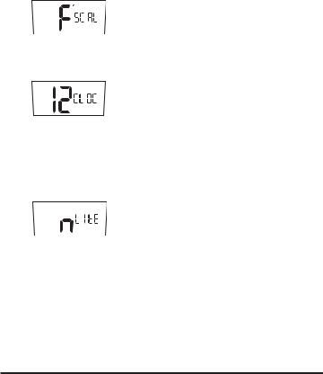
SCAL = Scale in °F (Fahrenheit) or °C (Celsius).
CLOC = Set clock to 12 or 24 hour format.
LITE = Display backlight always on ”y” or off ”n”. Also called the nightlight feature. If the thermostat has been wired with 24V AC (R and C terminals) then this feature will be displayed and the setting can be changed.
7

DIFF = The differential keeps the thermostat from turning on for small changes in temperature. When in Fahrenheit the range is 0.5 to 3.0 Degrees. In Celsius the range is 0.5 to 1.5 Degrees. The differential is factory set at 1.0 °F (0.5 °C). This means that whenever the room temperature is more than 1 °F (0.5 °C) different from the set temperature the system will turn on. If the system is turning on too often, increase the differential setting. Note that a larger differential will mean the room temperature changes more before the system turns on.
DIF2 = Second Stage Differential = Operates with the first stage to control a second heating/cooling system. This number will be added to the first stage differential (See: Two Stage Systems).
If the first stage is running too often lower the settings. This will turn the second stage on to help the first stage. If both stages are coming on too often then increase this setting to delay the second stage. Available on RS6220/RS6320.
DLY2 = Second Stage Delay = This timer starts when the first stage turns on. It resets when the first stage turns off. If this timer runs out the second stage will turn on (See Two Stage Systems). Available on RS6220/RS6320.
DLY3 = Third Stage Delay = This timer starts when the second stage turns on. It resets when the second stage turns off. If this timer runs out the third stage will turn on. Available on RS6320 only. (See Three Stage Systems).
8
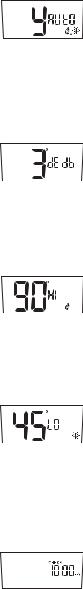
Auto changeover enable = Makes the auto changeover mode available. When chosen, the thermostat can automatically switch between heating and cooling. Note that the High and Low setpoint limits are not enforced in auto changeover mode.
DEDB = Deadband for auto changeover = the number of degrees that the room temperature can move away from the active setpoint until heating or cooling is called for. The larger the deadband the more the room temperature will vary. This can be from heat to cool or cool to heat.
HI = High Heat Limit = This is the highest allowed heating setpoint. The user will not be allowed to set a schedule setpoint or override temperature higher than this value.
NOTE: High Heat Limit is not enforced in auto changover mode.
LO = Low Cool Limit = This is the lowest allowed cooling setpoint. The user will not be allowed to set a schedule setpoint or override temperature lower than this value.
NOTE: Low Cool Limit is not enforced in auto changover mode.
CHECK = Timer to remind the home owner to maintain the filter. Default setting is off. The timer runs when the system is on. It can be set at 0 (OFF) or up to 9900 hours. When the time expires CHECK FLTR is displayed. Press the 
 and
and  buttons to restart the filter timer.
9

CYCL = Cycle Timer allows a compressor to rest between cycles. Can be set from 0 to 5 minutes in 1 min increments.
WARNING: A wrong short cycle setting can damage your equipment. This should only be changed by a trained HVAC professional.
CAL = Calibration offset. Changes the displayed temperature from the actual temperature by +3 to -3 degrees in one degree increments. Increasing the offset by +2 will cause the thermostat to display a temperature that is 2 degrees higher than the actual room temperature
Creating a Password – Protect the Settings
The buttons on the front of the thermostat can be locked with a password. To create a password:
1.Press the  and
and 

 buttons at the same time and hold them in for 5 seconds.
You will be asked for a 4 digit password.
2.Each digit is set using the  and
and  buttons. Press the

 to move to the next digit. Press
  to move back.
3.The password is saved after 5 seconds.
All of the front buttons are now locked out until the password is entered. Pressing any button will cause  to flash.
To unlock the buttons:
1.Push and hold the  and
and 
 buttons for 5 seconds until the request for password is displayed.
2.Enter the digits for the password by pressing the  and
and  buttons. Press the
 to move to the next digit. Press
 to move back.
3.When the correct password is set, wait for 5 seconds to unlock the system.
4.If the wrong password is entered the display will flash ---- for 5 seconds then return to normal.
Once the security has been disabled, a password needs to be recreated to protect the settings.
10
 Loading...