


300-208
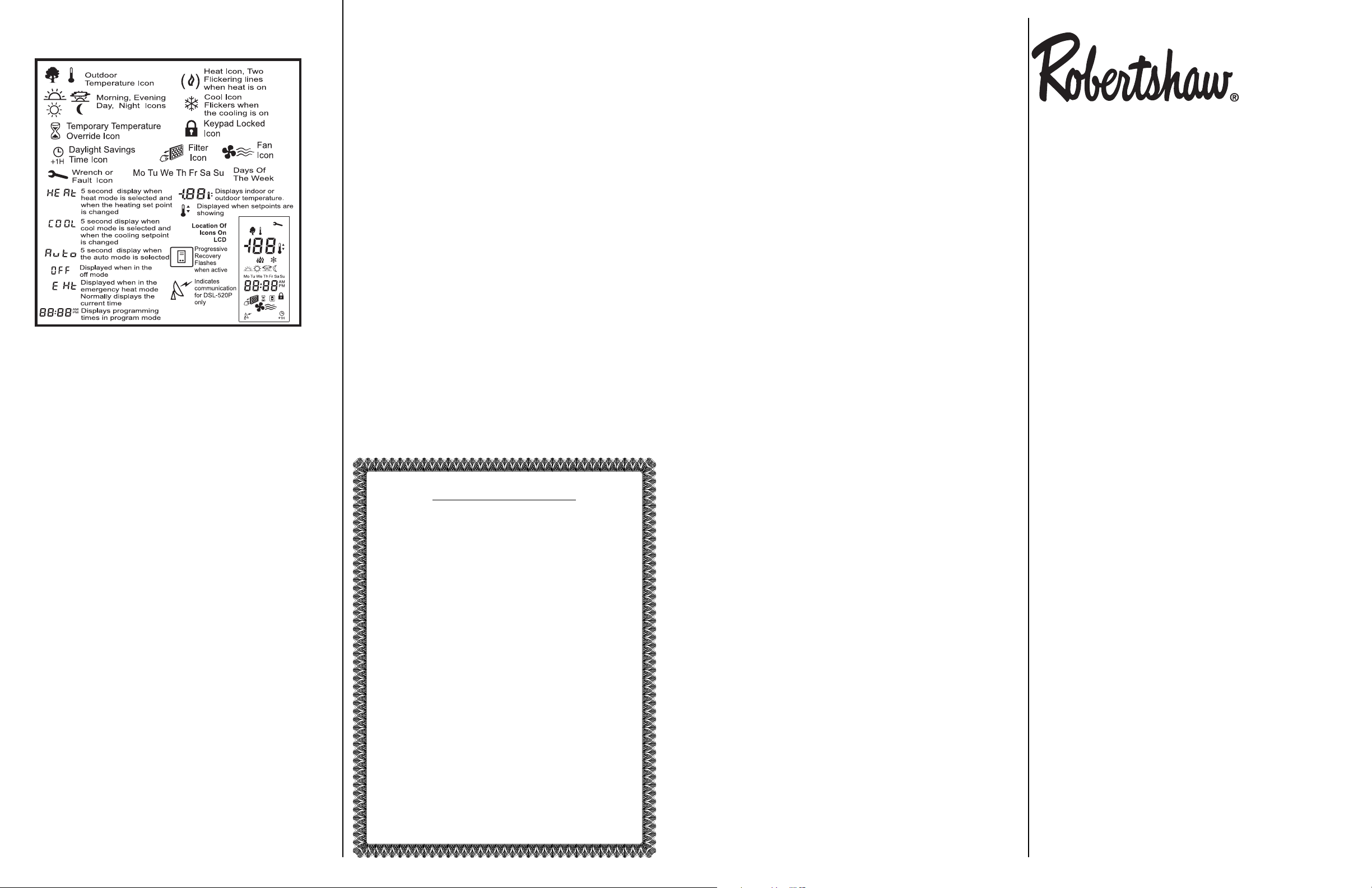
DESCRIPTION OF ICONS
Display icons vary according to the model. Your thermostat may
not display all of the icons shown.
Outdoor Hi & Lo Temperature Balance Points (Heat Pump Only)
With the optional Electronic Outdoor Temperature sensor, you can
select the outdoor balance points to inhibit the auxiliary heat
and/or compressor.
HibP – Press and hold the OUTDOOR button, then press the
MODE button. HibP will appear on the display. Raise or lower the
HibP by pressing the or button to set the temperature above
which the Auxiliary heat is locked out. Press the outdoor button
while showing the HibP and the thermostat will switch to show
LobP. LobP is used to lock out the compressor. Outdoor temperatures below the LobP will lock out the compressor. The factory
HibP and LobP setpoints are +48°C and -48°C.
DIP SWITCH OPTIONS AND FUNCTIONS
Positioning the DIP switches in either the ON or OFF position
enables you to choose between two different options. The DIP
switches are located on the interior of your thermostat and may
be accessed by following the procedure for removing the thermostat from the subbase. The following list describes your DIP
switch options.
DIP Switch No. DIP Switch OFF DIP Switch ON
1 Normal Add on
2 Not used (OFF position) Not used
3 4 minute minimum ON 2 minute minimum
ON
4 Keypad unlock Keypad lock
5 Economy Comfort
6 Not used (OFF position) Not used
7 LED #1+No icon LED #1+
% Filter icon
8 LED #2+No icon LED #2+
$ Fault icon
1. Normal or Add On Heat Pump In the NORMAL position the thermostat will allow the compressor and the auxiliary heat to be on at
the same time. In the ADD-ON position, the compressor is turned
off with a call for auxiliary heat.
2. Not Used This switch must remain in the OFF position.
3. 2 Minute or 4 Minute ON Times This option allows you to run the
equipment for either a 2 or 4 minute minimum off and on time.
4. Keypad Lock
#
In the ON position locks out all buttons except the
OUTDOOR temperature button.
5. Economy/Comfort In the OFF position, the thermostat will be in
ECONOMY mode. In the ON position the thermostat will be in
COMFORT mode.
6. Not Used This switch must remain in the OFF position.
7. LED #1 + Indication In the OFF position LED #1 will light when the
terminal is energized. In the ON position LED#1 will light and a
Filter
%
icon will be displayed on the LCD when the terminal is
energized.
8. LED #2 + Indication In the OFF position LED #2 will light when the
terminal is energized. In the ON position LED#2 will light and a
Fault
$
icon will be displayed on the LCD when the terminal is
energized.
SPECIFICATIONS
Rated Voltage 20-30 VAC, 24 nominal
Rated A.C. 0.050 Amps to 0.75 Amps continuous
Current per output with surges to 3 Amps Max.
Rated D.C. 0 Amps to 0.75 Amps continuous
Current per output with surges to 3 Amps Max.
Control Heating: 38° to 88°F in 1° Steps
Range 5° to 30°C in 1° Steps
Cooling: 60° to 108°F in 1° Steps
16° to 40°C in 1° Steps
Thermostat
Measurement Range 28° to 124°F or 0° to 48°C
O.D.T. Displayed
Range -50° to 119°F or -48° to 47°C
Control Accuracy ±0.5°C at 20°C, ±1°F at 68°F
Minimum (between heating and cooling)
Deadband 2°F or 1°C
NOTE: This thermostat contains electronic circuitry replacing the conventional mechanical anticipator.
One (1) Year Limited Warranty
The manufacturer warrants to the original purchaser that its
product and component parts will be free from defects in
workmanship and materials for a period of one (1) year from
the date of purchase. Return to the original point of purchase
for replacement of your product.
Warranty Limitations
This warranty begins at date of purchase.
Warranty is Void if:
The date code is defaced or removed.
The product has a defect or damage due to product alteration,
connection to an improper electrical supply, shipping and handling, accident, fire, flood, lightning, or other conditions beyond
the control of the manufacturer.
The product is not installed according to the manufacturer’s
instructions and specifications.
The product has been installed near sources of electromagnetic interference (EMI) such as arcing relay contact.
Owner’s Responsibility
Provide proof of purchase.
Provide normal care and maintenance.
Pay for freight, labor and travel.
Pay for service calls related to product installation.
Return any defective product.
In no event shall the manufacturer be liable for incidental or
consequential damages.
This warranty gives you specific legal rights and you may have
others which vary by state and/or province. For example, some
states and/or provinces do not allow the exclusion or limitation
of incidental or consequential damages so this exclusion may
not apply to you.
The manufacturer’s continuing commitment to quality products
may require a change in specifications without notice.
This equipment, if installed in strict accordance with the manufacturer’s instructions, complies with the limits for a Class B
computing device pursuant to Subpart J of Part 15 of FCC rules.
NEW & IMPROVED FEATURES
Your new electronic thermostat has been made even better by the
introduction of several new and improved features. Building on its
reputation for efficient and dependable operation, your thermostat
now offers the following list of enhancements.
Thermostat and Sensor Calibration
Release 3 provides easy calibration of the thermostat and remote
sensors. Simply press and hold the FAN button for 10 seconds
and adjust with the or buttons.
Push Button Auto Repeat
Programming is easier with the push button auto repeat feature.
GENERAL INFORMATION
The thermostat normally displays room temperature, mode of
operation and whether cooling or heating is currently on. The
six buttons on the front of the unit allow complete control of
your equipment.
You may select different heating and cooling setpoints for the
system to maintain, e.g., 70° in heating and 75° in cooling.
Raising or lowering the setpoints in heating or cooling is as simple as pushing a button. In addition, you may choose to display
the temperature in °F or °C.
The thermostat also allows you to select continuous fan operation
(useful when using an air cleaner) or have the fan come on with
the equipment.
BUTTON FUNCTIONS
Outdoor Press to display the outdoor temperature (optional)
Mode Press to select cool only, heat only, auto (cool &
heat), off or emergency heat
Fan Press for continuous fan or auto fan
Day/Night Press to alternate between day and night
temperature setpoints
USER CONTROLS
MODE
Select the desired mode of operation by repeated pressing of the
MODE button:
– Indicates cooling system only (the word COOL is
displayed for 5 seconds)
– Indicates heating system only (the word HEAT is
displayed for 5 seconds)
– Indicates both the heating & cooling systems
(the word AUTO is displayed for 5 seconds)
– Blinking indicates cool ON
– Flickering indicates heat ON
OFF – Disables controller so equipment will not operate
(fan operation is still possible in this mode)
Eht – Emergency heat
COOLING:
Select the temperature you want your equipment to maintain while
in the COOLING mode by pressing and holding the or buttons. The control setpoint temperature is displayed for 5 seconds.
HEATING:
Select the temperature you want your equipment to maintain
while in the HEATING mode by pressing and holding the or
buttons. The control setpoint temperature is displayed. Your new
electronic digital thermostat has been designed to provide accurate control and display of room temperature. It will also display
all relevant information of the system.
FAN:
The fan will come on automatically when the system is operating,
but there is no indication of this on the display. To select continuous fan operation, press the FAN button and the display will
show
. This is recommended for electronic air cleaners and
continuous ventilation requirements.
TEMPORARY TEMPERATURE OVERRIDE WITH
KEYPAD LOCKED
(The keypad may be locked to prevent tampering by selecting the
ON position of DIP switch #4.)
If the keypad is locked to prevent tampering you may still temporarily adjust the setpoint by ± 3° F or ± 3° C of the programmed day setpoint. Press the or button to raise or lower
the setpoint for a 1-hour period.
OFF MODE
To turn off the heating or cooling system, press the MODE button
until the word OFF appears on the LCD. It will remain displayed
until the mode is changed. The OFF mode prevents the system
from being energized.
Avoid using the OFF mode during extremely cold weather to prevent damage to the equipment from freezing.
AUTO CHANGEOVER MODE
You may set the thermostat to automatically switch from HEATING to COOLING mode by pressing the MODE button until the
word AUTO and both the heating
and cooling icons appear
on the LCD. The thermostat will energize the heating or cooling
system based on the temperatures established for both modes.
Operating Instructions
Single Compressor Heatpump
with Auxiliary Heat
Non-Programmable Thermostat
Model 300-208
111-110B
 Loading...