

Page 1
R
- LCD-2040
- LCD-2040
LCD-2040
Service Manual
Service Manual
Page 2
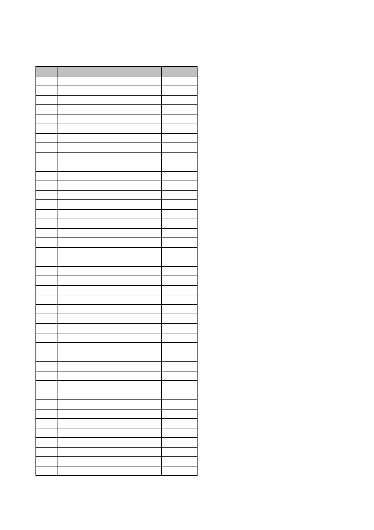
LCD-2040KLTN Spare Parts Pric List
No Description (Tae Young Telstar) U/P
1 FRONT PANEL $6,00
2 FRONT PANEL KNOB ASS'Y $0,90
3 CONTROL PCB ASS'Y $0,80
4 SPEAKER $1,00
5 MAIN SPEAKER $1,00
6 TWITTER SPEAKER $1,50
7 LCD PANEL $560,00
8 SHIELD CASE $6,00
9 MAIN PCB ASS'Y $67,00
10 AV TERMINAL BRACKET $0,25
11 INVERTER PCB ASS'Y $22,00
12 EMI SHIELD CASE $0,68
13 LED PCB ASS'Y $0,85
14 REAR COVER $3,80
15 TUNER PCB ASS'Y $18,30
16 AV TERMINAL SHEET $0,24
17 STAND FRAME $4,00
18 STAND LEG $3,00
19 HINGE ( Left ) $2,00
20 HINGE ( Right ) $2,00
21 STAND COVER ( FRONT ) $1,20
22 STAND COVER ( REAR ) $1,20
23 BOTTOM FRAME $3,00
24 SPEAKER FRAM( R ) $1,20
25 SPEAKER FRAM( L ) $1,20
26 EMI SPONGE(300X15X20) $1,20
27 REMOTE CONTROL $3,00
28 DC ADAPTOR $28,00
29 POWER CABLE $2,00
30 15 PIN D-SUB CABLE $1,50
31 AUDIO CABLE $0,75
32 IC EEPROM 24C16 $0,39
33 IC TTX SAA5264 $8,90
34 IC EEPROM 24C02 $0,25
35 IC MICOM, S3P863AXZZ $3,00
36 IC RGB S/W , TEA5114A $0,65
37 IC VIDEO S/W, TEA4625 $2,10
38 IC ADC , AD9883A $5,60
39 FET , FDS4435C $0,68
40 REGULATOR , KIA7808AF $0,30
41 REGULATOR , KIA78DL05F $0,28
42 REGULATOR, LD1117DT33 $0,52
Page 3
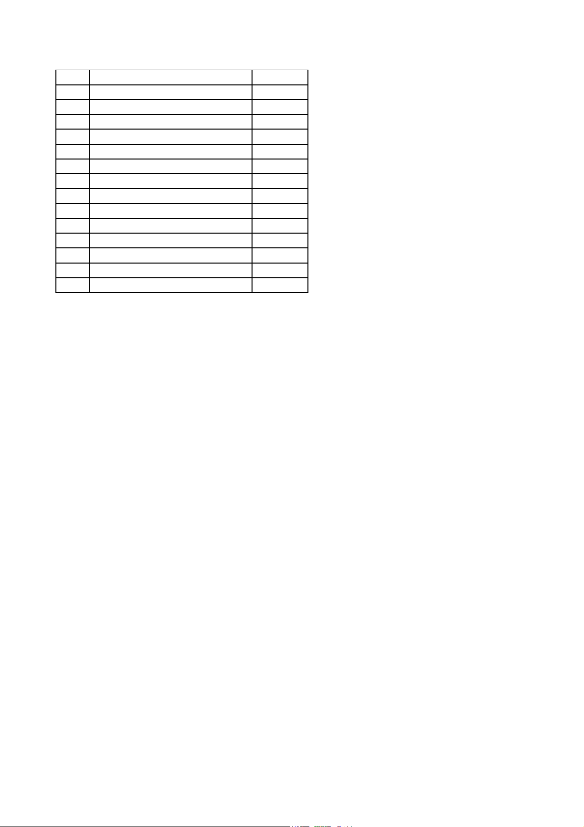
43 REGULATOR, SI-8050SD $0,72
IC IMAGE SCALLER, MX88L284AEC
IC AUDIO AMP , TDA8542AT / 20 PIN
44 REGULATOR, RC1587M33 $0,55
45 IC AUDIO, MSP3410G-B8 $7,50
46
47 IC LVDS, SIL164CT64 / 64PIN $4,30
48
49 IC VIDEO , VPC3230D-B3 $13,60
50 CHIP X-TAL, 12MHz / 33pF $0,20
51 CHIP X-TAL, 14.31818MHz / 33pF $0,20
52 CHIP X-TAL , 18,432MHz / 15pF $0,20
53 CHIP X-TAL , 20.25MHz / 15pF $0,20
54 IC RESET , KIA7042 $0,19
55 IC MEMORY , HY57V161610 $1,30
56 COLOR GIFT BOX $3,30
57 MANUAL $3,00
$9,80
$1,10
Page 4

SERVICE MANUAL
1. Detail Specification
1-1. PANEL
1-2. IN/OUT JACK
1-3. User Interface Specification
1-4. Electrical Specification
1-5. Available PC Input Mode & Video Timing Standard
1-6. OSD Specification ( America )
1-7. OSD Specification ( *** )
1-8. Factory mode OSD Specification
2. Adjustment Specification
2-1. Adjustment of CLOCK DELAY
2-2. Adjustment of AUTO COLOR GAIN
2-3. Setting Instruction of OPTION
2-4. Adjustment Instruction of VPC3230
3. Inspection Specification
3-1. Inspection of LCD PANEL
3-2. Inspection of INVERTOR
3-3. Inspection of ASSY-CONTROL
3-4. Inspection of ASSY-MAIN
4. Block Diagram
5. Circuit Diagram
6. General Specification
7. Troubleshooting
8. Parts List
- Contents -
9. Main PCB Drawing
Page 5

SERVICE MANUAL
1. Detail Specification
1-1. LCD Panel
LG-Philips LCD Panel : LC151X01-A3 : 15.1"( Panel Link Type )
LC201V1-A3 : 20.1"
1-2. In/Out Jack
Power Supply Input : Din Jack
Antenna Input : 75ohm Unbalanced Din-Jack Type
PC Input : 15pin D-sub Jack ( Female Type )
PC Audio Input : Phone Jack ( Stereo Type )
Composite Video In : RCA Jack
DVD In : RCA Jack (Y, Cb, Cr) - * 20.1" Model Only
S-Video In
Audio Input : RCA Jack ( When Composite or S-Video input )
EURO SCART Jack
Head-Phone Output Jack : Phone Jack ( When the Jack insert, Main Sound is mute. )
Audio Out : RCA Jack ( Monitor Out )
Video Out : RCA Jack ( Monitor Out )
Page 6

SERVICE MANUAL
1-3. User Interface
7 Panel Key
Power , Menu , Select , Vol Up , Vol Down , CH Up , CH Down
3 Color LED
Red : Stand by Condition
Green : Power On Condition
Scarlet : SLEEP TIME On Condition
Green Blink : When the PC Mode, Inserted D-sub Jack but
H,V Sync is not input or PC Power Save Mode
Remocon Receiver
Remocon ( Pal ; 41Key, NTSC ; 29Key )
On Screen Display
Control using OSD
OSD Language : English, German, Italian etc.
Plug & Play : DDC - 1/2B
Factory Mode
Mode for controlling the adjustment item & Panel Option in mass production
Page 7

SERVICE MANUAL
1-4. Electrical Specification
TV Color Standard : PAL,SECAM ( NTSC System : NTSC )
TV Sound Standard : B/G,I,D/K ( NTSC System : M )
TV Stereo Sound : NICAM Stereo , A2 Stereo ( NTSC System : BTSC )
TV Receiving Range : VHF LOW( 2 ~ H ), VHF-HIGH( I ~ W+26 ),
UHF (W+27~78)
Total 100CH ( NTSC System : 181CH )
Sound Output : RMS 1.5W X 2CH
Power Supply : AC / DC Adaptor ( DC12V , 5A , 50 /60 HZ )
Input Power : AC 100V ~ 265V
Power Consumption : Stand-by : 3W , Power On : 45W
Video Input Level : 1 Vp_p , 75 ohm
Audio Input Level : 500mVrms
PC Input Level : Analog RGB Input ( H,V Separator )
See 1-5. Available PC Input Mode & Video Timing Standard.
Audio Output Level : 500mVrms
Head-Phone Output Level : 100mW
Page 8
SERVICE MANUAL
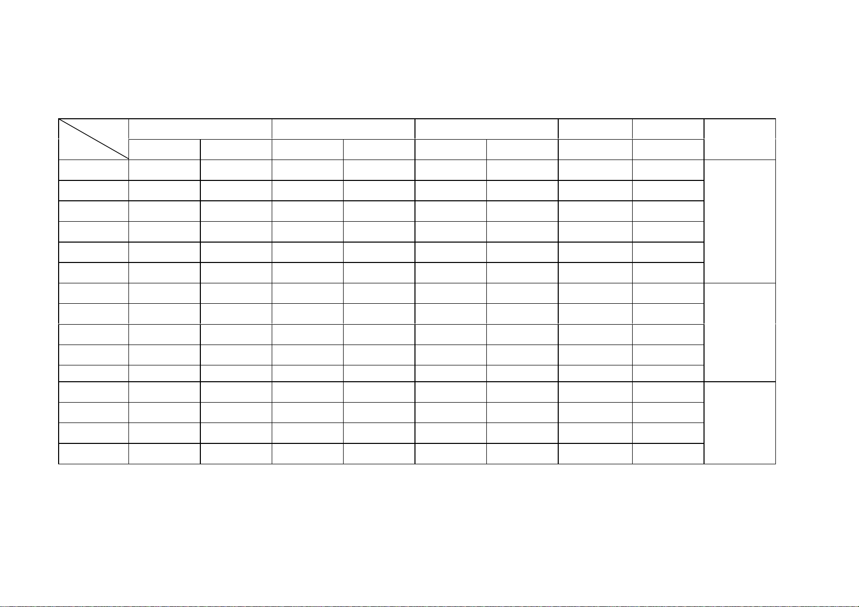
1-5. Available PC Input Mode & Video Timing Standard
Resolution Horizontal Vertical Clock Time
H V ( KHz ) Pol. ( Hz ) Pol. ( MHz ) ( nsec )
IBM 640 350 31.469 P 70.087 N 25.175 39.722
IBM 640 480 31.469 N 59.940 N 25.175 39.722
VESA 640 480 37.861 N 72.809 N 31.500 31.746
VESA 640 480 37.500 N 75.000 N 31.500 31.746
VESA 640 480 43.269 N 85.008 N 36.000 27.778
IBM 720 400 31.465 N 70.087 P 28.322 35.308
VESA 800 600 31.156 N/P 56.250 N/P 36.000 27.778
VESA 800 600 37.879 P 60.317 P 40.000 25.000
VESA 800 600 48.077 P 72.188 P 50.000 20.000
VESA 800 600 48.875 P 75.000 P 49.500 20.202
VESA 800 600 53.674 P 85.061 P 56.250 17.778
VESA 1024 768 48.363 N 60.004 N 65.000 15.358
VESA 1024 768 56.476 N 70.069 N 75.000 13.333
VESA 1024 768 60.023 P 75.029 P 78.750 12.698
Remarks
VGA
SVGA
XGA
VESA 1024 768 68.677 P 84.997 P 94.500 10.582
Page 9

SERVICE MANUAL
1-6. OSD Specification
PICTURE
CONTRAST
BRIGHTNESS
COLOR TEMPERAT ( PC input mode only )
STANDARD , 6500K , USER, RESET , 9300K
SHARPNESS ( Not Available PC MODE )
COLOR ( Not Available PC MODE )
TINT ( NTSC System Only )
SOUND
BASS
TREBLE
BALANCE
MTS ( S.MODE )
GEOMETRY ( PC input mode only )
H-POSITION
V-POSITION
AUTO POSITION
Page 10

FUNCTION
TRACKING ( PC input mode only )
AUTO TRACKING
CLOCK
PHASE
INFORMATION
TUNING ( TV input mode only )
SORT
AUTO TUNING
MANUAL TUNING
FINE TUNING
CH SKIP
LANGUAGE ( PAL/SECAM System )
CAPTION ( NTSC System )
V-CHIP ( NTSC System )
SERVICE MANUAL
Page 11

SERVICE MANUAL
1-8. Factory Mode OSD Specification
How to use Factory Mode
Press Power & Select Key in Panel Control key, and go to Factory mode.
Factory ADJ
CLOCK DELAY
AUTO COLOR GAIN
OPTION
TTX LOCAL
TTX E/W
MX88L281 1
AD9884 1 ( PC input mode only )
AD9884 2 ( PC input mode only )
SUB C VCP
SUB C CHG CURRENT
INIT VCO CURRENT
VPC3230 ( excluding PC MODE )
CONTRAST
BRIGHTNESS
PEAKING
CIP CONTRAST
CIP BRIGHT
** In mass production, adjust only Factory ADJ item, do not adjust other Modes.
( In the time of variation of A/S & initial condition of screen quality , built in other Modes for controlling )
Page 12

SERVICE MANUAL
2. Adjustment Instruction ( Factory ADJ )
2-1. Adjustment instruction of CLOCK DELAY
1. Adjustment item : Adjust the dispersion happening in the time of matching ASSY-MAIN and LCD PANEL .
(As the contact status of the CONNCETOR for connecting LCD PANEL, dispersion happens )
2. Adjustment Process : After assembling the SET , do the adjustment.
3. Preliminary adjustment :
1) Connect the outlet VIDEO PATTERN GENERATOR ( ANALOG RGB & SEPARATE H,V OUT ) to INPUT
( 15PIN D-sub with VGA CABLE )
2) TEST PATTERN: 1DOT BLACK, Select WHITE PATTERN.
( In the case of the tool of MSPG-925L, select PATTERN NO.28 )
3) Select Output FORMAT into 1024 x 768 @85HZ. (Select MODEL : 21)
4) Turn on the SET, and them select in PC MODE.
4. Adjustment Instruction :
1) Press SEL & Power Key in Front panel at the same time , go to Factory mode
2) Select CLOCK DELAY ( including in FACTORY ADJ MENU ) with CH UP/DOWN KEY in Factory mode
3) Changing the level of CLOCK DELAY with VOL UP/DOWN KEY, adjust to the noiseless level in screen
( variable range : 0 ~ 15, DEFAULT : 15 )
Page 13

SERVICE MANUAL
2-2. Adjustment Instruction of AUTO COLOR GAIN
1. Adjustment Item : Function of automatically setting ADC LEVEL of AD9884 with ANALOG RGB ( D-sub ) signal .
( WHITE BALANCE & CONTRAST adjustment )
2. Adjustment Process : After assembling the SET , do the adjustment .
3. Preliminary Adjustment
: 1) Connect Outlet of VIDEO PATTERN GENERATOR to the input terminal of CVBS.
2) TEST PATTERN : Select COLOR BAR PATTERN
3) Turn on the SET, and then select in VIDEO MODE.
4. Adjustment Instruction
: 1) Press SEL & Power Key in Front Panel at the same time, and go to Factory mode.
2) In Factory mode, select Auto Color Gain in Factory ADJ.
3) Press VOL UP KEY , and then displaying the phrase " Processing " , AUTO Adjustment start
4) When adjustment is completed , the phrase " Processing " disappears
=> caution : In the course of Processing, do not remove the signal.
Page 14

SERVICE MANUAL
2-3. Setting Instruction for OPTION
1. OPTION : - X2 - BYPASS
=> Using 6 BIT PANEL
=> Back-Light Control of Inverter
( Bright Max : LOW , Min : HIGH )
2. OPTION : - X2 - INVERT
=> Using 6 BIT PANEL
=> Back-Light Control of Inverter voltage polarity
( Bright Max : HIGH , Min : LOW )
3. OPTION : - X3 - BYPASS
=> Using 8 BIT PANEL
=> Back-Light Control of Inverter voltage polarity
( Bright Max : LOW , Min : HIGH )
4. OPTION : - X3 - INVERT
=> Using 8 BIT PANEL
=> Back-Light Control of Inverter voltage polarity
( Bright Max : HIGH , Min : LOW )
Select no 4 in the case that no 4 is not selected .
Page 15

SERVICE MANUAL
2-4. Adjustment Instruction of VPC3230
1. Adjustment item : Function of adjusting DEFAULT VALUE of VPC3230 DEVICE.
2. Adjustment process : After assembling the SET, do the adjustment .
3. Preliminary adjustment
: 1) Connect Outlet of VIDEO PATTERN GENERATOR to the input terminal of CVBS.
2) TEST PATTERN : Select COLOR BAR PATTERN
3) Turn on the SET, and then select in VIDEO MODE.
4. Adjustment Instruction
: 1) Press SEL & Power Key in Front Panel at the same time , and go to Factory mode.
2) Select VPC3230 in Factory mode.
3) Adjust to the following levels with VOLUME UP/DOWN, CH UP/DOWN
- CONTRAST 52
- BRIGHT 9
- PEAKING 0
- CIP CONTRAST 7
- CIP BRIGHT 7
No need to adjust when the SET is stable
.
Page 16
SERVICE MANUAL
3. Inspection Specification
3-1. Input Specification of LCD PANEL ( Total Inspection )
Inspection Procedure Standard Remark
1 Turn off the power of JIG ( check the power of JIG )
2 Connect BACK LIGHT CONNECTOR of LCD PANEL to JIG
3 Connect PANEL Connector of JIG to LCD PANEL
4 Turn on the power of JIG POWER ON
5 After receiving Black Pattern, check the number of radiant Pixel No the matter
6 After receiving White Pattern, check the number of radiantless Pixel 2 Pixel and less
7 After receiving White Pattern, check the spots No the matter
8 Turn off the power of JIG
9 Disconnect PANEL Connector
10 Disconnect Back Light Connector
1) In order to prevent the spots of PANEL, inspect with Gloves on
RMK
2) In the time of connecting & disconnecting the Connector, surely turn off the power of JIG,
and then go on the inspection.
3) Test Pattern : Full White & Full Black Pattern
Page 17
SERVICE MANUAL
3-2. Inspection Specification of INVERTOR ( Total inspection )
Insepction procedure Standard
1 Turn off the power of JIG ( check the power of JIG )
2 Connect 2P CONNECTOR in the upper part of JIG to CN3 Back-Light Con'
3 Connect 2P CONNECTOR in the lower part of JIG to CN2 Back-Light Con'
4 Connect 5P CONNECTOR of JIG to CN1 Inverter Con'
5 Turn on the power of JIG POWER ON
6 Check the screen is displaying normally
7 Change “ Brightness” and check the variation of brightness level
8 Turn off the power of JIG
9 Disconnect the Connector
1) TEST PATTERN : White / Black Pattern
RMK
2) In the time of connection & disconnection the CONNECTOR,
surely turn off the power of JIG , and then go on inspection
=> warning : pay attention to high voltage
Page 18
SERVICE MANUAL
3-3. Inspection specification of ASSY-CONTROL
Inspection procedure standard Remark
1 Turn off the power of JIG ( check the power of JIG )
2 Connect 7P Connector with JIG
3 Check the tight insertion of TACT SW Tight insertion
4 Turn on the power of JIG.
5 Check the color of LED is red STAND BY : RED LED
6
Press POWER KEY , and then check the screen is displaying & LED is lighting in green .
7 Press each KEY and check the function CHECK key SW
8 With REMOTECON , turn off the power Check REF LED
9 Turn off the power of the JIG
10 Disconnect the Connector
1) After checking the connecting status of 15PIN in JIG , go on the inspection
RMK
: in case of no sign , KEY may not work .
POWER ON : GREEN LED
Page 19
SERVICE MANUAL
Operating procedure OSD specification
1. POWER KEY setting
2. MENU KEY setting
3. SELECT KEY setting
4. KEY setting
5. KEY setting
6. KEY setting
7. KEY settinh
=>
POWER ON
Page 20

SERVICE MANUAL
3-4. INSPECTION SPECIFICATION OF ASSY-MAIN
3-4-1 INSPECTION IN TV MODE
1. Required tool : PM5518 ( RF PATTERN GENERATOR – built in SAP function) , simple JIG
2. Preliminary inspection : 1) set up PM5518 : RF FREQ' : 55.25MHZ ,
PATTERN : COLOR BAR ,SOUND : STEREO ( 3KHZ/1KHZ),
SYSTEM : PAL/NTSC - 6 (REAR PANEL) RF GAIN :60dBuV
3. Inspection procedure :
1) Inserting Connector
2) Power on the JIG , POWER ON the Set.
3) TUNING ( in case of NTSC, select channel 2, in case of PAL/SECAM , AUTO TUNING
: select the stored channel .
4) Check COLOR & the sound of SPEAKER ( L : 3KHZ , R : 1KHZ )
5) Changing VOLUME , check up & down of sound ( VOLUME 0 : MUTE , others : LEVEL up & down )
6) With MUTE KEY of REMOCON , Check MUTE function
7) With MTS KEY of REMOCON, after converting to MONO, check SOUND
8) When converting " CONTRAST" in PICTURE MENU , check the conversion of light & darkness in screen
9) When converting " BRIGHTNESS" of PICTURE MENU , check the conversion of brightness in screen
10) When converting " COLOR" of PICTURE MENU, check COLOR GAINING ( 0 : NO COLOR )
11) In the time of change " TINT" in PICTURE MENU , check COLOR VARIATION.
12) With P.STD KEY of REMOCON , check the conversion of the Screen
13) With S.STD KEY of REMOCON , check the conversion of the Sound
14) With SURROUND KEY of REMOCON, check the conversion of the Sound
15) Convert to STAND BY MODE.
16) Power off the JIG , and then disconnect JACK & CONNECTOR.
Page 21

SERVICE MANUAL
3-4-2. Inspection item in VIDEO MODE
1. Required tool; : PM5518 ( PATTERN GENERATOR ) , VTR ( NTSC ) , SCOPE , JIG1 ,
2. Preliminary item : 1) set up PM5518 : RF FREQ' :55.25MHZ , PATTERN : COLOR BAR ,
SOUND : STEREO ( 3KHZ/1KHZ )
SYSTEM : PAL/NTSC - 6 ( REAR PANEL ) RF GAIN : 60dBuV
3. Insepction procedure :
1) Inserting Connector
2) Power on JIG , and then POWER ON the set. ( Check the color of LED : GREEN )
3) Inserting RCA-JACK BLOCK S-VHS JACK & PC AUDIO JACK.
4) After converting to VIDEO MODE , check the screen & Sound .
5) In the screen of SCOPE check that the output is L : 3KHZ , R : 1KHZ
6) With S.MODE KEY of Remote control , after converting to MONO , check the SOUND
( L /R :3KHZ )
7) After converting to S-VIDEO MODE , check the screen & SOUND
8) After converting PC MODE, check the output of PC AUDIO
9) After inserting SCART CABLE
10) After converting to STAND BY MODE, check the color of LED ( LED color : RED )
11) Power off JIG , and then disconnect JACK & CONNECTOR
Page 22

SERVICE MANUAL
3-4-3. Inspection in PC MODE
1. Inspection item : in each MODE setting PC , inspect the status
2. Preliminary item : 1) MSPG-925L Setting
- Pattern : Select 1DOT W/BLACK ( PATTERN NO : 28 , MODEL NO.: 21 )
3. Inspection procedure:
1) Afrer inserting 15pin JACK and DC-JACK, POWER ON
2) 2) Select PC MODE.
3) After converting MODEL NO of MSPG-925L to 21 ( 1024 x 768 @85Hz ) , check the screen status
4) After converting MODEL NO of MSPG-925L to 15 ( 800 x 600 @ 85Hz ) , check the screen status
5) After converting MODEL NO of MSPG-925L to 10 ( 720 x 400 @ 70.1Hz ), check the screen status.
6) After converting MODEL NO of MSPG-925L to ( 640 x 480 @ 85Hz ) , check the screen status
7) After converting MODEL NO of MSPG-925L to 1 ( 640 x 350 @ 70.1Hz ) , check the screen status
8) With AUTO POSITION , set up the screen position
9) After converting MODEL NO of MSPG-925L to 28 ( 1024 x 768 @ 85Hz ) ,
In OSD MENU / FUNCTION / TRACKING , with AUTO TRACKING , set up the screen position
10) Disconnect DC-JACK , 15pin JACK
Page 23
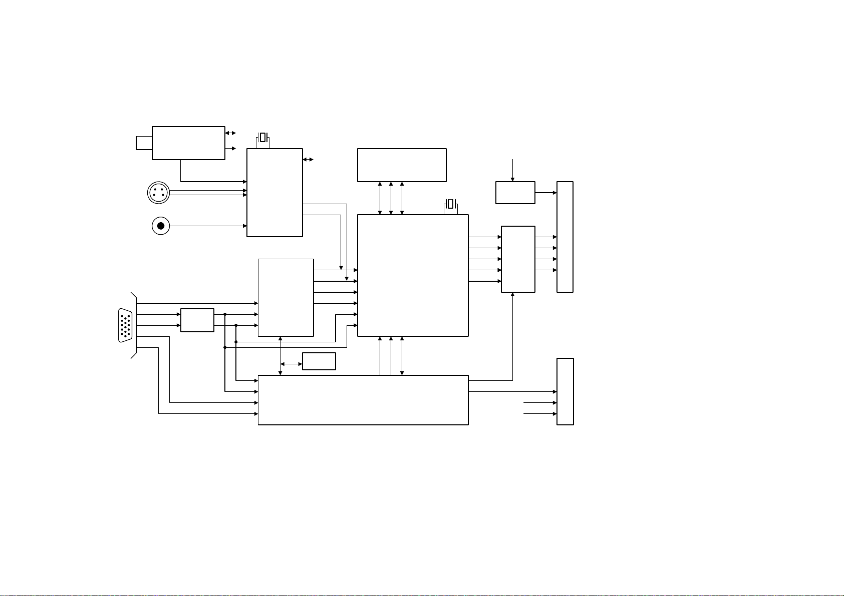
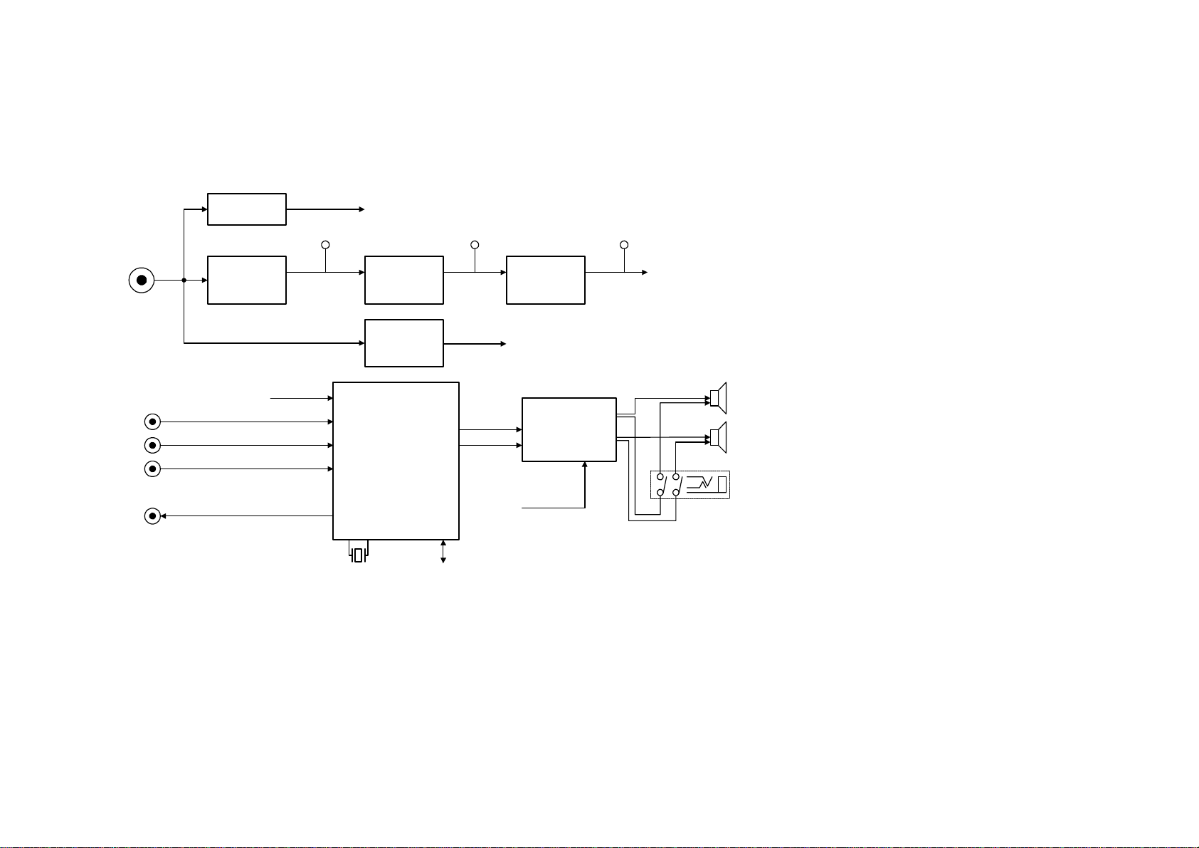
4. BLOCK DIAGRAM
TUNER
VPC3230
VIDEO
DECODER
SERVICE MANUAL
2M SRAM x2
MX88L284
FDS4435
FET SW
PANEL LINK
SIL140A
LCD CONNECTOR
74F14
AD9883
ADC & PLL
IMAGE SCALER
24C16
EEPROM
S3P863A
MICOM
Page 24
78L05
REGULATOR
SERVICE MANUAL
FDS4435
FET SW
LM2596
REGULATOR
KA7808R
REGULATOR
MSP34X0G
AUDIO
PROCESSOR
RC1587M33
REGULATOR
TDA8542ATSSO
UND AMP
Page 25

BLOCK DIAGRAM
3.3V
5V
5V
3.3V
3.3V
3.3V
5V
3.3V
5V
3.3V
8V
5V
OPTION
5V
5V
12V
8V
Page 26

5. Circuit Diagram (15.1" LCD TV)
POWER
CONNECTOR
(DC 12V)
JA801
PDJ005
1
2
3
C820
100nF
12Vcc
C807
220uF/16V(DIP)
F801
R251 010
C801
220uF/16V(DIP)
+
+
LM2576S-5.0/SI-8050SD
C808
100nF
IC801
KIA78DL05F
1
Vin
L801
BEAD
C804
100nF
C805
100nF
C806
220uF/16V(DIP)
+
POWER
OFF
IC803
1
IN
F/B
2
2 1
L804
47uH/SMD
D801
MBRS340
+
C809
220uF/16V(DIP)
GND
345
OUT
ON/OFF
R803
0(LM2576S)
IN
100nF
ON
C810
OUT
G
2
R802 22K
BEAD
L802
3
1
3 2
5Vcc
+
C811
220uF/16V(DIP)
R801
10K
Q801
BC848
C802
100nF
C812
100nF
5VA
C803
47uF/16V
+
IC802
FDS4435C
1
S
2
3
4 5
D
S
D
S
D
GD
IC804
RC1587M33
3
IN
OUT
G
1
8
7
6
2
C813
220uF/16V(DIP)
12Vcc
3.3Vcc
BEAD
L803
+
C814
100nF
+
C815
220uF/16V(DIP)
IC805
Vin
C818
100nF
+
C819
47uF/16V
1
KIA7808AF
IN
2
OUT
G
3
C816
100nF
+
C817
47uF/16V
8Vcc
Page 27

SCART_ID
DSUB_ID
5VM
C002
100nF
2
3
4
IC002
CN002
POST-HEADER(5P)
1
2
3
4
5
OPTION
A1
A2
GND
WAFER(3P)
+
VCCA0
WP
SCL
SDA
24C16(DIP)
5VM
BUS_STOP
R006 15K
R013 1K
CN03M
C003
10uF/16V
81
7
6
5
CN01M
WA FER(5P)
1
2
3
4
5
R014
1K
5VM
SCL
SDA
R010
47K
DDC_SDA
DDC_SCL
R009
22K
TP006
KEY_IN
1
2
TP007
3
100
R016
R017
100
RX
TX
TP001
TP002
TP003
TP004
TP005
BUS_STOP
R011
47K
EXT_MUTE
BL_BRI
5VA
R012
47K
R020
4.7K
R022
R023 220
5VM
POWER
Q001
BC848
5VM
220
IC003
KIA7042
R001 1K
C001
1nF
R004
R025
1K
C009
100nF
R007
C006
100nF
RX
TX
X001
12Mhz
10K
10K
1
3 2
Q002
BC848
5VA
5VM
R021
4.7K
R024
1
IN
L001
10uH
C005
10uF/16V
C007 33pF
4.7K
OUT
G
2
C010
10uF/16V
3 2
C008
1
+
33pF
3
+
IC001
KS88C6348
1
IR IN
2
LED-G
3
LED-R
4
SCART ID
5
D-SUB ID
6
BUS STOP
7
PWR_KEY
8
RGB SW
9
TXD
10
RXD
11
VCC
12
GND
13
XTAL
14
XTAL
15
TEST
16
DDC-SDA
17
DDC-SCL
18
RESET
19
POWER
20
EXT_MUTE
21
BL_BRI
BLON
A_RESET
PC SEL
RGB ID
5V DET
KEY-IN
VCC
GND
Hsync
Vsync
BUF ENA
MX RST
MX ENA
MX SDA
MX SCL
SDA
SCL
42
41
40
39
38
37
36
35
34
33
32
N.C
31
30
29
N.C
28
N.C
27
N.C
26
25
24
23
22
R005 100
R008
C004
1nF
R018 1K
R019 1K
5VM
R003
R002
2.7K
2.7K
BLON
SDA
100
KEY_IN
R015
1.3K
SCL
AV_RESET
PANEL_POWER
5VM
Hsync
Vsync
BUFEN
MX_RESET
MXCS
MXSDA
MXSCL
Page 28

L365
C360
C361
10uF/16V
100nF
DDC_SCL
DDC_SDA
DSUB_ID
L363
EF-1T2 012-330JT
3
EF-1T2012-330JT
3
L366
3
10
11
12
13
14
15
EF-1T2 012-330JT
JA360
PDC013
9
1
2
3
4
5
6
7
8
L364
EF-1T2012-330JT
3
L367
EF-1T2012-330JT
3
L368
EF-1T2012-330JT
R360
10
R361
75
R363
10
R364
75
R366
10
3
R368
75
C378
10pF
C381
10pF
C383
10pF
Vsync
Hsync
VPLL
SDA
SCL
C385
39nF
R369
1K
R371
1K
C379 47nF
C380 47nF
C382 47nF
C384
3.9nF
R376 680
R377 680
R373
3.3K
L361
10uH
C386 100nF
C387 100nF
3.3Vcc
VD
2627394245465152596211222369787934
VDVDVDVDVDVDVDVDVD
54
R_IN
48
G_IN
49
SOG_IN
43
B_IN
31
VSYNC
30
HSYNC
29
COAST
33
FILT
37
MIDSCV
58
REF BYPASS
38
CLAMP
57
SDA
56
SCL
55
A0
GND
GND
GND
GND
1102021242528323640414447505360616368
IC361
LD1117DT33
2
+
L362
10uH
1
L360
10uH
VOP
VD
VDD
VDD
VDD
IC360
AD9883A
GND
GND
GND
GND
GND
GND
GND
GND
GND
GND
GND
5Vcc
C362
100nF
3
VDD
VDD
GND
GND
VDD
GND
GND
GND
80
10uF/16V
+
VPLL
35
PVD
PVD
DATACK
HSOUT
SOGOUT
VSOUT
C363
R0
R1
R2
R3
R4
R5
R6
R7
G0
G1
G2
G3
G4
G5
G6
G7
B0
B1
B2
B3
B4
B5
B6
B7
C369
10uF/16V
+
77
76
75
74
73
72
71
70
9
8
7
6
5
4
3
2
19
18
17
16
15
14
13
12
67
66
65
64
1
3
5
7
1
3
5
7
1
3
5
7
1
3
5
7
1
3
5
7
1
3
5
7
C364
10uF/16V
+
C370
100nF
R375 100
C371
100nF
C365
100nF
VD
2
4
6
8
2
4
6
8
2
4
6
8
2
4
6
8
2
4
6
8
2
4
6
8
C366
100nF
C372
10uF/16V
R362
8P4R-100
R365
8P4R-100
R367
8P4R-100
8P4R-100
R370
8P4R-100
R372
8P4R-100
R374
+
C367
100nF
VOP
C373
100nF
PDA0
PDA1
PDA2
PDA3
PDA4
PDA5
PDA6
PDA7
PDA8
PDA9
PDA10
PDA11
PDA12
PDA13
PDA14
PDA15
PDA16
PDA17
PDA18
PDA19
PDA20
PDA21
PDA22
PDA23
C388
not insert
C368
100nF
C374
100nF
C375
100nF
PDA[0..23]
DCLKA
C376
100nF
C377
100nF
L369
EF-1T2012-330JT
3
L370
EF-1T2012-330JT
3
R378
22
R382
22
C389
330PF
D360
KDS226
C391
330pF
5Vcc
3
1
2
R380
4.7K
R383
4.7K
3
1
D361
KDS226
2
R379
22
R381
22
2
3
4
5
6
7
IC362
74F14FC
/Y1
A2
/Y2
A3
/Y3
GND
141
VCCA1
13
A6
/Y6
A5
/Y5
A4
/Y4
C390
100nF
12
11
10
9
8
Hsync
Vsync
Page 29

TTX_H_SYNC
TTX_V_SYNC
TTX_H_SYNC
TTX_V_SYNC
R302 100
R303 100
RCA_CVBS
SCART_CVBS
SVHS_Y
SVHS_C
TV_CVBS
R_CVBS
S_CVBS
JA301
PMJ014
TV_CVBS
SDA
SCL
TP2
JA701_4
12
43
JA701_3
TV_CVBS
L307
EF-1T2012-330JT
L309
EF-1T2012-330JT
C334
1uF
C343
1uF
1uF
C353
1uF
C355
1uF
C358
100nF
R335 100
R339 100
TP1
EF-1T2012-330JT
5
TP3
EF-1T2012-330JT
3
3
IC302
TEA6425D
L302
5
6
8
10
3
3
L304
R_CVBS
S_CVBS
8Vcc
L312
10uH
Vccp
IN1
IN2
IN3
IN4
IN5
IN6
SDA
214311
7129
SUB
SCL
SVHS_C
SVHS_Y
OUT1
OUT2
OUT3
OUT4
OUT5
OUT6
OUT7
OUT8
L301
5Vcc
10uH
R301
Q301
15K
BC848
TTX_CVBS
L303
R309
2.2uH
L305
2.2uH
L306
2.2uH
L308
2.2uH
L310
2.2uH
C398
100nF
C332
10uF/16V
1
R332
4.7K
75
R310
75
R312
75
R314
75
R316
75
+
Q302
BC848
3 2
R340
1K
R341
75
R311
75
R313
75
R315
75
R317
75
20
Vcc
19
18
17
16
15
14
13
GND
R307
1K
3 2
C312
100pF
C397
100pF
C318
100pF
C320
100pF
C323
100pF
5Vcc
EXT_FB
EXT_B
EXT_G
EXT_R
R330
1
C311 470nF
C313 470nF
C316 470nF
C319 470nF
C321 470nF
L311
10uH
75
EF-1T2012-330JT
R308
22K
C327
47uF/16V
R323
270
L318
3
C301
47uF/16V
C306
470nF
C328
220nF
+
R324
270
C302
220nF
+
C329
1.5nF
L313
2.2uH
L315
2.2uH
L316
2.2uH
R325
270
CVBS_OUT
C303
1.5nF
C314
47nF
C330
390pF
TV_CVBS
C315
47uF/16V
C324
47nF
R319
75
R320
75
R321
75
C304
390pF
+
SVHS-C
SVHS-Y
TV-CVBS
RCA-CVBS
SCART-CVBS
C325
47uF/16V
+
C356
10uF/16V
+
C359
10uF/16V
C345
270pF
C346
270pF
C357
100nF
+
C307
6pF/NPO
C310
6pF/NPO
R318
1K
C347
270pF
R336
33k
C305
2.2nF
X301
20.25MHz
57
58
59
60
61
62
63
64
NC
ASGF
XTAL1
65
GNDF
VRT
I2CSEL
ISGND
VSUPF
VOUT
CIN
VIN1
VIN2
VIN3
VIN4
VSUPAI
GNDAI
VREF
FB1IN
AISGND
C333
470nF
C335
470nF
C342
470nF
R328
47K
Q304
BC848
1
XTAL2
B1/CB1IN
G1/Y1IN
R1/CR1IN
B2/CB2IN
1234567891011121314151617181920212223
R329
470
R331 150
R333 220
3 2
R337
510
1
R338
300
VS
CLK5
FPDAT
VSTBY
VPC3230D B3
G2/Y2IN
R2/CR2IN
ASGFNCVSUPCAP
C336
100nF
C349
220nF
L317
10uH
32
Q303
BC858
L319
R334
EF-1T2012-330JT
75
R304 100
R305 100
R306 100
AVO
INTLC
FSY/HC
MSY/HS
IC301
VSUPD
GNDD
GNDCAP
C350
C351
R326
100
1.5nF
390pF
5Vcc
TV_V_OUT
3
C308
47nF
VSUPSY
SCL
SCL
GNDSY
SDA
R327
680
SDA
PDA8
PDA9
C0
RESQ
R322
4.7K
AV_RESET
C1
TEST
C399
470nF
PDA10
C2
VGAV
PDA11
C3
YCOEQ
C309
68nF
5Vcc
GNDC
FFIE
VSUPC
FFWE
PDA12
C4
FFRSTW
PDA13
C5
FFRE
PDA14
C6
FFOE
PDA15
41664267436844694570467147724873497450755176527753785479558056
C7
VSUPY
GNDY
GNDLLC
VSUPLLC
VSUPPA
GNDPA
CLK20
24
C337
390pF
LLC1
LLC2
PDA21
PDA22
PDA19
PDA20
PDA[8..15]
C339
220nF
C340
47uF/16V
PDA0
PDA1
PDA2
PDA3
PDA4
PDA5
PDA6
PDA7
PDA[0..7]
PDA23
L314
3.3Vcc
10uH
+
40
Y0
39
Y1
38
Y2
37
Y3
36
C317
68nF
35
34
Y4
33
Y5
32
Y6
31
Y7
C322
68nF
30
29
28
27
26
25
C326
1.5nF
C331
47nF
C338
1.5nF
Page 30

TTX_CVBS
1
A0
Vdd
2
A1
R/P
3
A2
SCL
4 5
Vss SDA
ICX2
24C02
CX08
47pF
RX14
1K
RX15
1K
SCART_FB
SCART_ID
5Vcc
RX03
4.7K
8
7
6
CX09
TTX_23
100nF
LS01
EF-1T2012-330JT
RS06
75
EF-1T2012-330JT
1
P2.0/PWM
2
P2.1/PWM0
3
P2.2/PWM1
4
P2.3/PWM2
5
P2.4/PWM3
6
P2.5/PWM4
7
P2.6/PWM5
8
P2.7/PWM6
9
P3.0/ADC0
10
P3.1/ADC1
11
P3.2/ADC2
RX04
4.7K
12
P3.3/ADC3
13
Vssc
14
SCL(NVRAM)
15
SDA(NVRAM)
16
P0.2
17
P0.3
18
P0.4
19
P0.5
20
P0.6
21
P0.7
22
Vssa
23
CX10
100nF
CX11
100nF
RX16
24K
LS02
CVBS0
24
CVBS1
25
SYNC_FILTER
26 27
IREF FRAME
SCART_CVBS
3
TP206
SC1_R_IN
3
SC1_L_IN
ICX1
SAA5264(DIP)
TP201
TP203
TP210
TP211
SDA
Vddp
RESET
XTALOUT
XTALIN
OSCGND
Vddc
Vssp
VSYNC
HSYNC
VDS
Vdda
P3.4/PWM7
COR
TEST
20
18
16
14
12
10
8
6
4
2
JAS1
PMJ022
P1.5
P1.4
SCL
P1.3
P1.2
P1.1
P1.0
12Vcc
QS01
BC848
3 2
ICZ1
Z86129
CS01
100nF
RZ01 0
RZ02 0
RZ03 0
ICS1
TEA5114A
2
3
4
5
6
7
8
GND
R2
G1
G2
B1
B2
FB1
52
51
TTX_50
TTX_49
TTX_37
TTX_36
TTX_35
TTX_34
TTX_33
TTX_32
TTX_31
21
19
17
15
13
11
9
7
5
3
1
CX02
56pF
CX04
100nF
CX06
100nF
TP209
TP202
TP204
TP205
TP207
RX01 100
RX02 100
CX12
100nF
CX01
1nF
XX0112MHz
CX03
56pF
RX05 1K
RX06 1K
RX07 1K
RX08 240
RX09 240
RX10 240
CX07
22uF/16V
+
3.3Vcc
TP208
LX02
10uH
TV_V_OUT
+
CX05
22uF/16V
LS03
EF-1T2012-330JT
SCART-R
LS04
3
EF-1T2012-330JT
SCART-G
LS05
3
EF-1T2012-330JT
SCART-B
3
TV_L_OUT
TV_R_OUT
LX01
10uH
RS07
75
RX11
150
SDA
SCL
RS08
75
RX12
150
3.3Vcc
TTX_V_SYNC
TTX_H_SYNC
TTX_FB
TTX_R
TTX_G
TTX_B
RX13
150
RS09
75
SCART_R
SCART_G
SCART_B
RGB_SW
RGB_SW
RGB_SW
SCART_R
RS10 3.3K
SCART_G
RS11 3.3K
SCART_B
RS12 3.3K
5Vcc
LZ01
10uH
QS02
1
BC848
3 2
TTX_R
QS03
1
BC848
TTX_G
3 2
TTX_B
QS04
1
BC848
3 2
SCART_FB
TTX_FB
RGB_SW
CS03
470nF
CS04
470nF
CS05
470nF
CS06
470nF
CS07
470nF
CS08
470nF
RS05
3.3K
1
TTX_34
18 1
R-OUT Vss
TTX_35
17
F/B
16 3
SDO B-OUT
TTX_49
15
SCL
TTX_50
14
SDA
TTX_37
13
Vin/INTRO
TTX_31
12
Vdd
11
Vss(A)
RZ08
10K
10
RREF
50
49
48
47
46
45
44
43
42
41
40
39
38
37
36
35
34
R
33
G
32
B
31
30
29
28
ROUTR1
RCON
VCC
GOUT
GCON
BOUT
FBOUT
G-OUT
CSYNC
FB2
CVBS
SEN
SMS
CS02
10uF/16V
RS01 220
161
15
14
RS02 220
13
12
RS03 220
11
10
9
RZ04 0
TTX_33
2
TTX_32
RZ05
1K
4
TTX_36
5
HIN
6
TTX_23
7
CZ09
100nF
8
9
LPF
CZ07
682
RZ06
6.8K
CZ02
560pF
CZ08
683
EXT_R
EXT_G
EXT_B
EXT_FB
Page 31

C604
C605
100nF
100nF
+
R615 1K
Hsync
Vsync
DCLKA
C611
100nF
C606
100nF
C603
100nF
3.3Vcc VDDP
C601
10uF/16V
MXCS
MXSDA
MXSCL
MX_RESET
VDDP
L601
10uH
R601 100
R611 100
R612 100
C607
100nF
C608
100nF
C614
100nF
C609
100nF
R617
R618
C610
100nF
C612
10uF/16V
1K
1K
MD15
MD14
MD13
MD12
MD11
MD10
MD9
MD8
MD7
MD6
MD5
MD4
MD3
MD2
MD1
MD0
+
R616
4.7K
108
107
I2CDLK
105
106
VDDP
GOUT2
I2CDATA
MD[0..31]
GOUT1
GNDP
GOUT0
LDTG
LVSYNC
LHSYNC
RA0
RA1
RA2
RA3
RA4
RA5
RA6
GNDP
RA7
VDDP
VDD
GA0
GA1
GA2
GA3
GA4
GA5
GA6
GA7
BA0
BA1
BA2
BA3
BA4
BA5
BA6
BA7
GNDP
LCKA
GND
LCKB
GNDP
RB0
VDDP
RB1
RB2
RB3
RB4
RB5
RB6
RB7
GNDP
GB0
GB1
GB2
GB3
TP601
104
103
102
101
100
99
98
97
96
95
94
93
92
91
90
VDD
89
88
87
86
85
84
83
82
81
80
79
78
77
76
75
74
73
72
71
70
69
68
67
66
65
64
63
62
61
60
59
58
57
56
55
54
53
R614
100
TP602
TP604
C615
22pF
TP603
LCKA
RA0
RA1
RA2
RA3
RA4
RA5
RA6
RA7
GA0
GA1
GA2
GA3
GA4
GA5
GA6
GA7
BA0
BA1
BA2
BA3
BA4
BA5
BA6
BA7
LDTG
LVSYNC
LHSYNC
RA[0..7]
GA[0..7]
BA[0..7]
MCLK
MD16
MD23
MD27
125
1
8
124
VDDP
MD26
6 374
R604
123
MD24
MD25
5
8P4R-100
122
MD25
MD24
2
121
MD26
MD31
1
8
120
MD27
MD30
6 374
R605
119
MD28
MD29
5
8P4R-100
118
MD29
MD28
2
117
MD30
116
MD31
115
GNDP
DQMA2
114
DQM3
113
DQM2
111
112
VDD
OSDBLINK
110
OSDB
109
OSDG
OSDR
MD18
MD20
MD22
MD19
MD17
MD21
1
5
1
8
133
6 374
R602
132
MD16
8P4R-100
131
MD17
2
130
MD18
8
129
MD19
6 374
R603
128
MD20
5
8P4R-100
127
MD21
2
126
MD22
MD23
R606
C602
100
MCKE
WE
RAS
DQMA1
DQMA0
CAS
MA[0..10]
150
151
152
153
154
155
156
CKE
WE#
CAS#
RAS#
VDDP
DQM0
GNDP
GND
MD15
MD14
MD13
MD12
MD11
MD10
MD9
MD8
VDDP
VDD
MD7
GNDP
MD6
MD5
MD4
MD3
MD2
MD1
MD0
AD0
AD1
AD2
AD3
AD4
AD5/SBCS#
AD6/SBDATA
AD7/SBCLK
GNDP
CPUA15/BCS#
VDDP
ALE
WR#
RD#
TMCLK
RST#
GIPOA0
GIPOA1
GIPOA2
GIPOA3
GIPOA4
GIPOA5
IRQ
SOGCS
TDCLK/CSYNC
HSYNC1
VSYNC1
GOUT3
GND
DCLKA
GNDP
DQM1
157
1
3
5
7
1
3
5
7
1
3
5
7
1
3
5
7
C613
100nF
R613
D601
LED
2
R607
4
8P4R-100
6
8
2
R608
4
8P4R-100
6
8
2
R609
4
8P4R-100
6
8
2
R610
4
8P4R-100
6
8
4.7K
1
2
158
159
160
161
162
163
164
165
166
167
168
169
170
171
172
173
174
175
176
177
178
179
180
181
182
183
184
185
186
187
188
189
190
191
192
193
194
195
196
197
198
199
200
201
202
203
204
205
206
207
208
470
MA9
MA5
MA3
MA2
MA7
MA1
MA4
MA0
MA6
MA8
MA10
134
135
136
137
138
139
140
141
142
143
144
145
146
147
148
149
MA9
MA8
MA7
MA6
MA5
MA4
MA3
MA2
MA1
GNDP
MA0
VDDP
MA10
GND
MCLK
GNDP
IC601
MX88L284AEC
3.3Vcc
C616
10uF/16V
BUSTYPE
VDDP
PIXINA7
PIXINA5
PIXINA4
PIXINA3
PIXINA2
PIXINA1
PIXINA0
CLAMP
PIXINA15
PIXINA14
PIXINA13
PIXINA12
PIXINA11
PIXINA10
PIXINA9
PIXINA8
VDD
PIXINA23
PIXINA22
PIXINA21
PIXINA20
PIXINA19
PIXINA18
PIXINA17
PIXINA16
DDE
GND
GNDP
PIXINA6
123567891011121314151617181920212223242526272829303132433343536373839404142434445464748495051
PDA7
PDA6
PDA5
PDA4
PDA3
PDA2
PDA1
PDA0
PDA15
PDA8
PDA9
PDA12
PDA23
PDA14
PDA13
PDA10
PDA11
PDA20
PDA19
PDA22
PDA18
PDA21
VDD
C624
100nF
VDD
C619
+
100nF
C625
C626
C627
100nF
100nF
100nF
R619
4.7K
PDA[0..23]
L602
10uH
C617
+
100nF
C618
10uF/16V
AGND2
AGND1XIXO
AVDD1
AVDD2
VDDP
BB7
BB6
BB5
BB4
BB3
BB2
BB1
GNDP
BB0
VDDP
GB7
GB6
GB5
GB4
52
3.3Vcc
L603
10uH
+
C622
100nF
C628
22pF
C623
22pF
C621
10uF/16V
C620
PDA16
PDA17
100nF
X601
14.31818MHz/30pF
R620
1M
Page 32

MD[0..31]
3.3Vcc
C701
10uF/16V
+
C702
100nF
C703
100nF
C704
100nF
C705
100nF
C706
100nF
C707
100nF
3.3Vcc
C708
10uF/16V
+
C709
100nF
C710
100nF
C711
100nF
C712
100nF
C713
100nF
C714
100nF
MCLK
RAS
CAS
WE
MCKE
DQMA1
DQMA0
DQMA2
R701 8P4R-100
1
3
5
7
R702 8P4R-100
1
3
5
7
MA[0..10]
MCLK
RASB
2
CASB
4
WEB
6
CKEB
8
DQM1
2
DQM0
4
DQM2
6
8
MA8
MA9
MA10
MA4
MA5
MA6
MA7
R705 8P4R-100
MA0
1
MA1
3
MA2
5
MA3
7
DQM0
WEB
R703 8P4R-100
1
3
5
7
R704 8P4R-100
1
3
5
7
2
4
6
8
CASB
2
4
6
8
2
4
6
8
MD0
MD1
MD2
MD3
MD4
MD5
MD6
MD7
RASB
MB8
MB9
MB10
MB4
MB5
MB6
MB7
MB0
MB1
MB2
MB3
501
VSSVDD
2
DQ0
3
DQ1
4
VSSQ
5
DQ2
6
DQ3
7
VDDQ
8
DQ4
9
DQ5
10
VSSQ
11
DQ6
12
DQ7
13
VDDQ
14
LDQM
15
WE
16
CAS
17
RAS
18
CS
19
MB10
MB0
MB1
MB2
MB3 MB3
DQM2
A11
20
A10
21
A0
22
A1
23
A2
24
A3
25
VDD
IC701
KM416S1020C
DQ15
DQ14
VSSQ
DQ13
DQ12
VDDQ
DQ11
DQ10
VSSQ
DQ9
DQ8
VDDQ
N.C
UDQM
CLK
CKE
N.C
VSS
49
48
47
46
45
44
43
42
41
40
39
38
37
36
35
34
33
MB9
32
A9
A8
A7
A6
A5
A4
MB8
31
MB7
30
MB6
29
MB5
28
MB4
27
26
MD15
MD14
MD13
MD12
MD11
MD10
MD9
MD8
CKEB
DQM0
MCLK
WEB
DQM1
MB[0..10]
RASB
CASB
MD16
MD17
MD18
MD19
MD20
MD21
MD22
MD23
DQM2
MB10
MB0
MB1
MB2
2
3
4
5
6
7
8
9
10
11
12
13
14
15
16
17
18
19
20
21
22
23
24
25
DQ0
DQ1
VSSQ
DQ2
DQ3
VDDQ
DQ4
DQ5
VSSQ
DQ6
DQ7
VDDQ
LDQM
UDQM
WE
CAS
RAS
CS
A11
A10
A0
A1
A2
A3
VDD
IC702
KM416S1020C
VSSVDD
DQ15
DQ14
VSSQ
DQ13
DQ12
VDDQ
DQ11
DQ10
VSSQ
DQ9
DQ8
VDDQ
N.C
CLK
CKE
N.C
VSS
501
49
48
47
46
45
44
43
42
41
40
39
38
37
36
35
34
33
MB9
32
A9
A8
A7
A6
A5
A4
MB8
31
MB7
30
MB6
29
MB5
28
MB4
27
26
MD31
MD30
MD29
MD28
MD27
MD26
MD25
MD24
CKEB
MCLK
DQM1
Page 33

CN91M
WAFER(6P)
BLON
GND
BRT
GND
V-IN
3
2
1
NC
5
4
6
RA[0..7]
GA[0..7]
BA[0..7]
3.3Vcc
LCKA
L904
10uH
GA7
GA6
GA5
GA4
GA3
GA2
GA1
GA0
BA7
BA6
BA5
BA4
BA3
BA2
BA1
BA0
C902
100nF
PVCC
LVDS_VCC
+
C922
10uF/16V
RA0
RA1
RA2
41
42
43
44
45
484746
D18
D17
D16
D15
D14
D12
D13
GND
49
PVCC2
50
D11
51
D10
52
D9
53
D8
54
D7
55
D6
56
IDCK-
57
IDCK+
58
D5
59
D4
60
D3
61
D2
62
D1
63
D0
64
GND
VCCDEVREF
123456789101112131415
C923
100nF
HSYNC
VSYNC
IC901
SiI164
CTL3
CTL2
R902
CTL1
10K
RA5
RA4
RA3
38
39
40
D21
D20
D19
EDGEPDMSEN
C915
100nF
C904
100nF
TP901
L901
BEAD
TP904
C916
22uF/16V
+
C918
100nF
C905
100nF
TP914
TP915
TP902
+
C919
22uF/16V
TP903
CN92M
125HR-20MT
1
2
3
4
5
6
7
8
9
10
11
12
13
14
15
16
17
18
19
20
RX2+
RX2-
GND
RX1+
RX1-
GND
RX0+
RX0-
GND
RXC+
RXC-
GND
V_SYNC
H_SYNC
GND
3.3V
3.3V
5V
5V
5V
+
C906
22uF/16V
LCD Signal Connector
RA6
RA7
C907
100nF
LVDS_VCC
33
34
35
36
37
D23
D22
VCC
C908
100nF
DKEN
ISEL/RST
DSEL/SDA
VCC
REVD
AGND
AVCC
AGND
AVCC
TXC+
AGND
EXT_SW
PVCC
PGND
BSEL/SCL
GND
16
TX2+
TX2-
TX1+
TX1-
TX0+
TX0-
TXC-
32
31
30
29
28
27
26
25
24
23
22
21
20
19
18
17
10uF/16V
PVCC
C917
C911
100nF
R903
510
C909
100nF
C910
100nF
IC902
LD1117DT33
2
+
+
C912
10uF/16V
L902
10uH
5Vcc
3
1
12Vcc
3.3Vcc
BL_BRI
BLON
C903
22uF/16V
C913
22uF/16V
+
PANEL_VCC
+
BEAD
C914
100nF
L903
LDTG
LHSYNC
LVSYNC
BUFEN
R901
100
C901
100nF
C920
22uF/16V
PANEL_POWER
5Vcc
C921
100nF
+
R907
22K
ON
R906
1
10K
Q901
1
BC848
3 2
S
2
S
3
S
4 5
GD
IC903
FDS4435C
8
D
7
D
6
D
OFF
Page 34

CVBS
AUDIO
CN21M
Harness 10Pin
R208
4.7K
5Vcc
L206
10uH
SC1_R_IN
SC1_L_IN
N.C
VCC
SCL
SDA
SAS
N.C
VCC
C206
100pF
SIF
SIF_IN
1
2
3
4
5
6
7
8
9
10
C210
6pF
C221
10uF/16V
+
5Vcc
RGB_SW
C208
6pF
C212 56pF
C214 56pF
C216 56pF
C219
100nF
L208
EF-1T2012-330JT
L209
EF-1T2012-330JT
SIF_IN
TV_CVBS
18.432MhZ
3
3
X201
C220
100pF
JA301
PMJ014
1 3
4 5
6
R205
10K
R215 470
R216
65
470
C234
330pF
2
7
5Vcc
L201
10uH
R203
R201
100
100
1234567891011121314151617181920212223
NC
I2S_CL
I2C_CL
I2C_DA
STANDBYQ
ADR_SEL
D_CTR_OUT0
D_CTR_OUT1
NC
NC
AUD_CL_OUT
TP
XTAL_OUT
XTAL_IN
TESTEN
ANA_IN2+
ANA_IN-
ANA_IN1+
AVSUP
AVSUP
NC
64
C235
330pF
NC
63
AVSS
61
62
C228
10uF/16V
C230
470nF
C233
470nF
L211
EF-1T2012-330JT
3
L213
EF-1T2012-330JT
3
RCA_CVBS
AVSS
I2S_WS
MONO_IN
60
+
I2S_DA_OUT
NC
59
C225
470nF
C229
100nF
58
ADR_CL
ADR_DA
ADR_WS
I2S_DA_IN1
IC201
MSP3410G/3420G
ASG1
SC1_IN_L
SC1_IN_R
VREFTOP
57
C231
470nF
C236
330pF
R217
470
C201
10uF/16V
+
DVSUP
DVSUP
SC2_IN_L
SC2_IN_R
C232
470nF
C237
330pF
R218
470
DVSUP
ASG2
C202
100nF
R204
47K
DVSS
SC3_IN_R
C203
100pF
DVSS
DVSS
ASG4
SC3_IN_L
I2S_DA_IN2
SC4_IN_R
C238
470nF
C239
470nF
C240
330pF
NCNCNC
SC4_IN_L
10uF/16V
C226
SCL
SDA
AV_RESET
R202
1K
C204
470nF
L202
24
NC
NC
DACA_R
RESETQ
AHVSS
AGNDC
NC
+
C241
330pF
AHVSS
R219
R220
DACA_L
VREF2
DACM_R
DACM_L
DACM_SUB
SC2_OUT_R
SC2_OUT_L
VREF1
SC1_OUT_R
SC1_OUT_L
CAPL_A
AHVSUP
CAPL_M
NC
NC
41664267436844694570467147724873497450755176527753785479558056
C227
100nF
470
470
NC
NC
ASG3
EF-1T2012-330JT
EF-1T2012-330JT
L210
L212
25
26
27
28
29
30
31
32
33
34
35
36
37
38
39
40
C222
10uF/16V
3
3
C205
1nF
C217
+
10uF/16V
C218
+
10uF/16V
+
C207
1nF
R209 100
R210 100
R212 100
R213 100
C223
100pF
C224
100nF
3
2
1
JA203
PPJ35G
L207
10uH
MAIN_R
MAIN_L
C209
470nF
C211
470nF
C213
470nF
C215
470nF
8Vcc
EF-1T2012-330JT
R211
47K
EF-1T2012-330JT
R214
47K
L204
3
L205
3
EF-1T2012-330JT
R206
47K
L203
EF-1T2012-330JT
R207
47K
CVBS_OUT
3
3
TV_R_OUT
TV_L_OUT
2
7
JA202
PJ6054B
13
45
6
Page 35

8Vcc
L251
BEAD
MAIN_L
EXT_MUTE
MAIN_R
R255
22K
Ver B6 180K/B8 200K
C253
+
1uF/50V
C255
+
1uF/50V
R251
R253
10K
R254
10K
Q251
1
BC848
3 2
Ver B6 180K/B8 200K
IC251
TDA8542AT
C254
+
47uF/16V
R256
R252
100K
R257
100K
C251
C252
+
220uF/16V(DIP)
100nF
19
R+
R-
L+
L-
JA301
PMJ014
1
G
5
L
2
R
EF-1T2012-330JT
L253
GND VccR
11 12
OUTR +
GND
1
20
VccL
OUTR -
OUTL +
OUTL -
GND
7
N.C
18
3
8
13
C256
10uF/16V
+
EF-1T2012-330JT
L254
17
INR -
2
RGND
16
INR +
5
SVR
15
INL +
9
LGND
14
INL -
6
BTL/SE
4
MODE
GND
10
CN25M
WAFER(4P)
4
3
2
1
47
36
RL
C257
10uF/16V
+
R260
1K
R258
330
3
3
R259
330
R261
1K
Page 36

RM01
FRP-3051
3
2
1
RC02
47K
5Vcc
RC01
47
RC08
680
SAM5270
RC09
680
DL01
5Vcc
CC3
100nF
CN01C
Harness 5Pin
1
VCC
2
IR_IN
3
LED-R
LED-G
2
3 1
4
5
GND
LED_R
LED_G
RC03
2.2k
SW02
JTP1280A
SELC
RC04
1.3k
SW04
JTP1280A
VOL - MENU
RC05
620
SW03
JTP1280A
RC06
390
SW06
JTP1280A
CH -VOL +
RC07
390
SW05
JTP1280A
CH +
SW07
JTP1280A
SW01
JTP1280A
POWER
CN03C
Harness 3Pin
1
KEY_IN
2
GND
3
POWER
Page 37

TU01
TCPQ9091PD27D
100uF/16V
CT02
104
SCL
SDA
CT01
+
5V
N.C5VSCL
1
2
RT01
100
LT01
10uH AL03
B+
GND
1
2
N.C
VCC
3
SCL
SCL
3
SCL
4
SDA
SDA
4
SDA
RT02
100
SDA
SAS
5
5
SAS
6
N.C
SIF
7
SIF
6
N.C
CVBS
8
2'nd IF
7
B+
CVBS
8
9
VCC
CVBS5VAUDIO
9
10
AUDIO
10
AUDIO
CN21T
WAFER(10PIN)
Page 38

5. Circuit Diagram (20.1" LCD TV)
JA801
PDJ005
3
DC 15V
1
2
Vcc_SW
220uF/16V(DIP)
C807
F801
R251 010
C801
220uF/16V(DIP)
+
IC801
KA78L05AD
8 1
IN OUT
7
GND
6
GND
5
N.C
Vin
L801
BEAD
C804
100nF
C805
100nF
+
C806
220uF/16V(DIP)
+
POWER
R802 22K
ON
OFF
IC803
C808
100nF
LM2596S-5.0
1
IN
345
GND
OUT
ON/OFF
F/B
2
L804
47uH/SMD
D801
MBRS340
2 1
+
C809
220uF/16V(DIP)
C810
100nF
L802
BEAD
GND
GND
N.C
1
3 2
5Vcc
+
C811
220uF/16V(DIP)
R801
10K
Q801
2
3
4
BC848
C802
100nF
C812
100nF
5VA
C803
47uF/16V
+
IC802
FDS4435C
1
S
2
3
4 5
D
S
D
S
D
GD
IC804
RC1587M33
3
IN
OUT
G
1
8
7
6
2
C813
220uF/16V(DIP)
Vcc_SW
3.3Vcc
BEAD
L803
+
C814
100nF
+
C815
220uF/16V(DIP)
IC805
Vin
C818
100nF
+
C819
47uF/16V
KA7808R
1
3
IN
OUT
G
2
C816
100nF
+
C817
47uF/16V
8Vcc
Page 39

SCART_ID
DSUB_ID
5VM
C002
100nF
2
3
4
IC002
CN002
POST-HEADER(5P)
1
2
3
4
5
OPTION
A1
A2
GND
WAFER(3P)
+
VCCA0
WP
SCL
SDA
24C16(DIP)
5VM
BUS_STOP
R006 15K
R013 1K
CN03M
C003
10uF/16V
81
7
6
5
CN01M
WA FER(5P)
1
2
3
4
5
R014
1K
5VM
R010
47K
SCL
SDA
DDC_SDA
DDC_SCL
R009
22K
KEY_IN
1
2
3
100
R016
R017
100
RX
TX
BUS_STOP
R011
47K
EXT_MUTE
BL_BRI
5VA
R012
47K
R020
4.7K
R022
R023 220
5VM
POWER
Q001
BC848
5VM
220
IC003
KIA7042
R001 1K
C001
1nF
R004
R025
1K
C009
100nF
R007
C006
100nF
RX
TX
X001
12Mhz
10K
10K
1
3 2
Q002
BC848
5VA
5VM
R021
4.7K
R024
1
IN
L001
10uH
C005
10uF/16V
C007 33pF
4.7K
OUT
G
2
C010
10uF/16V
3 2
C008
1
+
33pF
3
+
IC001
KS88C6348
1
IR IN
2
LED-G
3
LED-R
4
SCART ID
5
D-SUB ID
6
BUS STOP
7
PWR_KEY
8
RGB SW
9
TXD
10
RXD
11
VCC
12
GND
13
XTAL
14
XTAL
15
TEST
16
DDC-SDA
17
DDC-SCL
18
RESET
19
POWER
20
EXT_MUTE
21
BL_BRI
BLON
A_RESET
PC SEL
RGB ID
5V DET
KEY-IN
VCC
GND
Hsync
Vsync
BUF ENA
MX RST
MX ENA
MX SDA
MX SCL
SDA
SCL
42
41
40
39
38
37
36
35
34
33
32
N.C
31
30
29
N.C
28
N.C
27
N.C
26
25
24
23
22
R005 100
R008
C004
1nF
R018 1K
R019 1K
5VM
R003
R002
2.7K
2.7K
BLON
SDA
100
KEY_IN
R015
1.3K
SCL
AV_RESET
PANEL_POWER
5VM
Hsync
Vsync
MX_RESET
MXCS
MXSDA
MXSCL
Page 40

L365
C360
C361
10uF/16V
100nF
DDC_SCL
DDC_SDA
DSUB_ID
L363
EF-1T2 012-330JT
3
EF-1T2012-330JT
3
L366
3
10
11
12
13
14
15
EF-1T2 012-330JT
JA013
PDC013
9
1
2
3
4
5
6
7
8
L364
EF-1T2012-330JT
3
L367
EF-1T2012-330JT
3
L368
EF-1T2012-330JT
R360
10
R361
75
R363
10
R364
75
R366
10
3
R368
75
C378
10pF
C381
10pF
C383
10pF
Vsync
Hsync
VPLL
SDA
SCL
C385
39nF
R369
1K
R371
1K
C379 47nF
C380 47nF
C382 47nF
C384
3.9nF
R376 680
R377 680
R373
3.3K
L361
10uH
C386 100nF
C387 100nF
3.3Vcc
VD
2627394245465152596211222369787934
VDVDVDVDVDVDVDVDVD
54
R_IN
48
G_IN
49
SOG_IN
43
B_IN
31
VSYNC
30
HSYNC
29
COAST
33
FILT
37
MIDSCV
58
REF BYPASS
38
CLAMP
57
SDA
56
SCL
55
A0
GND
GND
GND
GND
1102021242528323640414447505360616368
IC361
LD1117DT33
2
+
L362
10uH
1
L360
10uH
VOP
VD
VDD
VDD
VDD
IC360
AD9883A
GND
GND
GND
GND
GND
GND
GND
GND
GND
GND
GND
5Vcc
C362
100nF
3
VDD
VDD
GND
GND
VDD
GND
GND
GND
80
10uF/16V
+
VPLL
35
PVD
PVD
DATACK
HSOUT
SOGOUT
VSOUT
C363
R0
R1
R2
R3
R4
R5
R6
R7
G0
G1
G2
G3
G4
G5
G6
G7
B0
B1
B2
B3
B4
B5
B6
B7
C369
10uF/16V
+
77
76
75
74
73
72
71
70
9
8
7
6
5
4
3
2
19
18
17
16
15
14
13
12
67
66
65
64
1
3
5
7
1
3
5
7
1
3
5
7
1
3
5
7
1
3
5
7
1
3
5
7
C364
10uF/16V
+
C370
100nF
R375 22
C371
100nF
C365
100nF
VD
2
4
6
8
2
4
6
8
2
4
6
8
2
4
6
8
2
4
6
8
2
4
6
8
C366
100nF
C372
10uF/16V
R362
8P4R-100
R365
8P4R-100
R367
8P4R-100
8P4R-100
R370
8P4R-100
R372
8P4R-100
R374
C388
22pF/NPO
C367
C368
100nF
100nF
VOP
C374
C373
100nF
100nF
+
PDA0
PDA1
PDA2
PDA3
PDA4
PDA5
PDA6
PDA7
PDA8
PDA9
PDA10
PDA11
PDA12
PDA13
PDA14
PDA15
PDA16
PDA17
PDA18
PDA19
PDA20
PDA21
PDA22
PDA23
C375
100nF
PDA[0..23]
DCLKA
C376
100nF
C377
100nF
L369
EF-1T2012-330JT
3
L370
EF-1T2012-330JT
3
R378
22
R382
22
C389
330PF
D360
KDS226
C391
330pF
5Vcc
3
1
2
R380
4.7K
R383
4.7K
3
1
D361
KDS226
2
R379
22
R381
22
2
3
4
5
6
7
IC362
74F14FC
/Y1
A2
/Y2
A3
/Y3
GND
141
VCCA1
13
A6
/Y6
A5
/Y5
A4
/Y4
C390
100nF
12
11
10
9
8
Hsync
Vsync
Page 41

TTX_H_SYNC
TTX_V_SYNC
TTX_H_SYNC
TTX_V_SYNC
R302 100
R303 100
RCA_CVBS1
L307
EF-1T2012-330JT
SCART_CVBS
L310
EF-1T2012-330JT
RCA_CVBS2
L309
EF-1T2012-330JT
JA301A
PMJ014
TV_CVBS
SVHS_Y
SVHS_C
TV_CVBS
SDA
SCL
L301
10uH
5Vcc
R301
Q301
15K
BC848
1
TTX_CVBS
OUT1
OUT2
OUT3
OUT4
OUT5
OUT6
OUT7
OUT8
20
Vcc
GND
R341
75
R311
75
R313
75
R315
75
VCC_6425
19
18
17
16
15
14
13
L303
2.2uH
L305
2.2uH
L306
2.2uH
L308
2.2uH
C398
100nF
C332
10uF/16V
Q302
BC848
1
R332
4.7K
Q305
BC848
1
R342
4.7K
5Vcc
+
L302
JA701_4
EF-1T2012-330JT
12
43
5
JA701_3
EF-1T2012-330JT
TV_CVBS
IC302
TEA6425D
C334
1uF
C341
1uF
C343
1uF
C344
1uF
C348
1uF
C352
1uF
C353
1uF
C354
1uF
3
C355
1uF
3
C358
1uF
3
5
6
8
10
R335 100
R339 100
3
3
L304
VIDEO_CVBS
8Vcc
L312
10uH
Vccp
IN1
IN2
IN3
IN4
IN5
IN6
SDA
214311
SVHS_C
SVHS_Y
7129
SUB
SCL
R309
75
R310
75
R312
75
R314
75
3 2
VCC_6425
3 2
L311
10uH
R340
1K
R317
1K
R330
75
R316
75
3 2
R307
1K
C312
100pF
C397
100pF
C318
100pF
C320
100pF
C327
47uF/16V
EF-1T2012-330JT
VIDEO_CVBS
C311 470nF
C313 470nF
C316 470nF
C319 470nF
C328
220nF
+
L318
CVBS_OUT
3
R308
22K
C329
1.5nF
C301
47uF/16V
C306
470nF
C330
390pF
EXT_FB
EXT_B
EXT_G
EXT_R
+
C302
220nF
C314
47nF
C321
470nF
R323 270
R324 270
JA303
PJ6054B
1 3
4 5
9
C303
1.5nF
C315
47uF/16V
+
C324
47nF
L313 2.2uH
L315 2.2uH
L316 2.2uH
R325 270
Pr
2
Pb
Y
10
C304
390pF
R343
0
TV-CVBS
RCA-CVBS
DVD_IN
47uF/16V
SVHS-C
SVHS-Y
C325
+
R319
75
R320
75
R321
75
C307
6pF/NPO
C310
6pF/NPO
65
R318
1K
C345 270pF
L320
EF-1T2012-330JT
L321
3
EF-1T2012-330JT
L322
3
EF-1T2012-330JT
3
C305
2.2nF
X301
20.25MHz
57
58
59
60
61
62
63
64
NC
ASGF
XTAL1
XTAL2
GNDF
VRT
I2CSEL
ISGND
VSUPF
VOUT
CIN
VIN1
VIN2
VIN3
VIN4
VSUPAI
GNDAI
VREF
FB1IN
AISGND
B1/CB1IN
G1/Y1IN
R1/CR1IN
B2/CB2IN
1234567891011121314151617181920212223
C333
470nF
C335
470nF
C342
470nF
C396 470nF
C346 270pF
C347 270pF
R344 75
C393 270pF
C392 270pF
C392A 270pF
L323 2.2uH
VS
CLK5
VSTBY
FPDAT
VPC3230D B3
G2/Y2IN
R2/CR2IN
ASGFNCVSUPCAP
C336
100nF
C394 470nF
C395 470nF
C349
220nF
R346 75
R345 75
L325 2.2uH
L324 2.2uH
R304 100
R305 100
R306 100
AVO
INTLC
FSY/HC
MSY/HS
IC301
VSUPD
GNDD
GNDCAP
C350
C351
R326
1.5nF
390pF
100
C308
47nF
VSUPSY
SCL
SCL
PDA8
GNDSY
SDA
R327
680
SDA
TV_CVBS
PDA9
C1
C0
RESQ
TEST
C399
470nF
R322
4.7K
AV_RESET
PDA10
PDA11
C2
VGAV
C356
10uF/16V
+
C359
10uF/16V
C309
68nF
C3
YCOEQ
GNDC
FFIE
5Vcc
C357
100nF
+
VSUPC
FFWE
R336
33k
PDA12
C4
FFRSTW
PDA13
C5
FFRE
PDA14
R328
47K
Q304
BC848
1
C6
FFOE
PDA15
41664267436844694570467147724873497450755176527753785479558056
C7
VSUPLLC
CLK20
24
Y0
Y1
Y2
Y3
VSUPY
GNDY
Y4
Y5
Y6
Y7
GNDLLC
LLC1
LLC2
VSUPPA
GNDPA
C337
390pF
R329
470
R331 150
R333 220
3 2
R337
510
40
39
38
37
36
35
34
33
32
31
30
29
28
27
26
25
C338
1.5nF
1
C326
1.5nF
C331
47nF
R338
300
C317
68nF
C322
68nF
C339
220nF
32
Q303
BC858
R334
75
PDA0
PDA1
PDA2
PDA3
PDA4
PDA5
PDA6
PDA7
+
C340
47uF/16V
L317
10uH
L319
EF-1T2012-330JT
PDA21
PDA22
PDA19
PDA20
PDA[8..15]
L314
10uH
5Vcc
3
PDA[0..7]
PDA23
3.3Vcc
TV_V_OUT
R348 270
R349 270
R347 270
Page 42

TTX_CVBS
1
A0
Vdd
2
A1
R/P
3
A2
SCL
4 5
Vss SDA
ICX2
24C02
CX08
47pF
RX14
1K
RX15
1K
SCART_FB
SCART_ID
5Vcc
RX03
4.7K
8
7
6
CX09
TTX_23
100nF
LS01
EF-1T2012-330JT
RS06
75
EF-1T2012-330JT
1
P2.0/PWM
2
P2.1/PWM0
3
P2.2/PWM1
4
P2.3/PWM2
5
P2.4/PWM3
6
P2.5/PWM4
7
P2.6/PWM5
8
P2.7/PWM6
9
P3.0/ADC0
10
P3.1/ADC1
11
P3.2/ADC2
RX04
4.7K
12
P3.3/ADC3
13
Vssc
14
SCL(NVRAM)
15
SDA(NVRAM)
16
P0.2
17
P0.3
18
P0.4
19
P0.5
20
P0.6
21
P0.7
22
Vssa
23
CX10
100nF
CX11
100nF
RX16
24K
LS02
CVBS0
24
CVBS1
25
SYNC_FILTER
26 27
IREF FRAME
SCART_CVBS
3
SC1_R_IN
3
SC1_L_IN
ICX1
SAA5264(DIP)
SDA
Vddp
RESET
XTALOUT
XTALIN
OSCGND
Vddc
Vssp
VSYNC
HSYNC
VDS
Vdda
P3.4/PWM7
COR
TEST
20
18
16
14
12
10
8
6
4
2
JAS1
PMJ022
P1.5
P1.4
SCL
P1.3
P1.2
P1.1
P1.0
12Vcc
52
51
TTX_50
TTX_49
TTX_37
TTX_36
TTX_35
TTX_34
TTX_33
TTX_32
TTX_31
21
19
17
15
13
11
9
7
5
3
1
CX02
56pF
CX04
100nF
CX06
100nF
RX01 100
RX02 100
CX12
100nF
CX01
1nF
XX0112MHz
CX03
56pF
RX05 1K
RX06 1K
RX07 1K
RX08 240
RX09 240
RX10 240
CX07
22uF/16V
+
3.3Vcc
LX02
10uH
TV_V_OUT
+
CX05
22uF/16V
LS03
EF-1T2012-330JT
SCART-R
LS04
3
EF-1T2012-330JT
SCART-G
LS05
3
EF-1T2012-330JT
SCART-B
3
TV_L_OUT
LX01
10uH
RS07
75
RX11
150
SDA
SCL
RS08
75
RX12
150
3.3Vcc
TTX_V_SYNC
TTX_H_SYNC
TTX_FB
TTX_R
TTX_G
TTX_B
RX13
150
RS09
75
SCART_R
SCART_G
SCART_B
5Vcc
SCART_R
TTX_R
SCART_G
TTX_G
SCART_B
TTX_B
SCART_FB
TTX_FB
RGB_SW
LZ01
10uH
RS05
10K
CS03
470nF
CS04
470nF
CS05
470nF
CS06
470nF
CS07
470nF
CS08
470nF
1
50
49
48
47
46
45
44
43
42
41
40
39
38
37
36
35
34
R
33
G
32
B
31
30
29
28
CS01
100nF
RZ01 0
RZ02 0
RZ03 0
ICS1
TEA5114A
2
GND
3
R2
4
G1
5
G2
6
B1
7
B2
8
FB1
QS01
BC848
3 2
TTX_34
18 1
R-OUT Vss
TTX_35
17
F/B
16 3
SDO B-OUT
TTX_49
15
SCL
TTX_50
14
SDA
TTX_37
13
Vin/INTRO
TTX_31
12
Vdd
11
Vss(A)
RZ08
10K
10
RREF
ROUTR1
RCON
GOUT
GCON
BOUT
FBOUT
ICZ1
VCC
CS02
10uF/16V
RS01 220
161
15
14
RS02 220
13
12
RS03 220
11
10
FB2
9
RZ04 0
RS04
1K
2
G-OUT
4
SEN
5
HIN
6
SMS
7
CVBS
8
CSYNC
9
LPF
TTX_33
TTX_32
RZ05
1K
TTX_36
TTX_23
CZ07
100nF
CZ09
682
RZ06
6.8K
EXT_R
EXT_G
EXT_B
EXT_FB
CZ02
560pF
CZ08
683
Z86129
TV_R_OUT
Page 43

C604
C605
100nF
100nF
+
R615 1K
Hsync
Vsync
DCLKA
C611
100nF
C606
100nF
C603
100nF
3.3Vcc VDDP
C601
10uF/16V
MXCS
MXSDA
MXSCL
MX_RESET
VDDP
L601
10uH
R601 100
R611 100
R612 100
C607
100nF
C608
100nF
C614
100nF
C609
100nF
R617
R618
C610
100nF
C612
10uF/16V
1K
1K
MD15
MD14
MD13
MD12
MD11
MD10
MD9
MD8
MD7
MD6
MD5
MD4
MD3
MD2
MD1
MD0
+
R616
4.7K
1
3
5
7
1
3
5
7
1
3
5
7
1
3
5
7
C613
100nF
R613
D601
LED
2 1
MA[0..10]
2
4
6
8
2
4
6
8
2
4
6
8
2
4
6
8
4.7K
R607
8P4R-100
R608
8P4R-100
R609
8P4R-100
R610
8P4R-100
157
158
159
160
161
162
163
164
165
166
167
168
169
170
171
172
173
174
175
176
177
178
179
180
181
182
183
184
185
186
187
188
189
190
191
192
193
194
195
196
197
198
199
200
201
202
203
204
205
206
207
208
GNDP
GND
MD15
MD14
MD13
MD12
MD11
MD10
MD9
MD8
VDDP
VDD
MD7
GNDP
MD6
MD5
MD4
MD3
MD2
MD1
MD0
AD0
AD1
AD2
AD3
AD4
AD5/SBCS#
AD6/SBDATA
AD7/SBCLK
GNDP
CPUA15/BCS#
VDDP
ALE
WR#
RD#
TMCLK
RST#
GIPOA0
GIPOA1
GIPOA2
GIPOA3
GIPOA4
GIPOA5
IRQ
SOGCS
TDCLK/CSYNC
HSYNC1
VSYNC1
GOUT3
GND
DCLKA
GNDP
DQMA1
DQMA0
155
156
DQM1
154
DQM0
RAS
153
VDDP
CAS
152
RAS#
WE
151
CAS#
WE#
MCKE
150
CKE
MCLK
MD18
MD19
MD17
1
5
C602
22pF
R606
22
6 374
8
MA9
MA5
MA3
MA2
MA7
MA1
MA4
MA0
MA6
MA8
MA10
R602
8P4R-100
131
132
133
134
135
136
137
138
139
140
141
142
143
144
145
146
147
148
149
MA9
MA8
MA7
MA6
MA5
MA4
MA3
MA2
MA1
GNDP
MA0
VDDP
MA10
GND
MCLK
GNDP
MD16
MD17
MD18
IC601
MX88L284AEC
MD16
2
130
MD19
MD23
1
8
129
MD20
MD22
6 374
R603
128
MD21
5
8P4R-100
127
MD21
MD20
2
126
MD22
125
MD23
MD27
1
8
124
VDDP
MD26
6 374
R604
123
MD24
MD25
5
8P4R-100
122
MD25
MD24
2
121
MD26
MD31
1
8
120
MD27
MD30
6 374
R605
119
MD28
MD29
5
8P4R-100
118
MD29
MD28
2
117
MD30
116
MD31
115
GNDP
DQMA2
114
DQM3
113
DQM2
111
112
VDD
OSDBLINK
110
OSDB
109
OSDG
108
OSDR
107
I2CDLK
I2CDATA
106
GOUT2
105
VDDP
MD[0..31]
GOUT1
GNDP
GOUT0
LDTG
LVSYNC
LHSYNC
RA0
RA1
RA2
RA3
RA4
RA5
RA6
GNDP
RA7
VDDP
VDD
GA0
GA1
GA2
GA3
GA4
GA5
GA6
GA7
BA0
BA1
BA2
BA3
BA4
BA5
BA6
BA7
GNDP
LCKA
GND
LCKB
GNDP
RB0
VDDP
RB1
RB2
RB3
RB4
RB5
RB6
RB7
GNDP
GB0
GB1
GB2
GB3
LDTG
LVSYNC
LHSYNC
104
103
102
101
100
99
98
97
96
95
94
93
92
91
90
VDD
89
88
87
86
85
84
83
82
81
80
79
78
77
76
75
74
73
72
71
70
69
68
67
66
65
64
63
62
61
60
59
58
57
56
55
54
53
R614
22
C615
22pF
LCKA
RA0
RA1
RA2
RA3
RA4
RA5
RA6
RA7
GA0
GA1
GA2
GA3
GA4
GA5
GA6
GA7
BA0
BA1
BA2
BA3
BA4
BA5
BA6
BA7
RA[0..7]
GA[0..7]
BA[0..7]
3.3Vcc
C616
10uF/16V
BUSTYPE
VDDP
PIXINA7
PIXINA5
PIXINA4
PIXINA3
PIXINA2
PIXINA1
PIXINA0
CLAMP
PIXINA15
PIXINA14
PIXINA13
PIXINA12
PIXINA11
PIXINA10
PIXINA9
PIXINA8
VDD
PIXINA23
PIXINA22
PIXINA21
PIXINA20
PIXINA19
PIXINA18
PIXINA17
PIXINA16
DDE
GND
GNDP
PIXINA6
123567891011121314151617181920212223242526272829303132433343536373839404142434445464748495051
PDA7
PDA6
PDA5
PDA4
PDA3
PDA2
PDA1
PDA0
PDA15
PDA8
PDA9
PDA12
PDA23
PDA14
PDA13
PDA10
PDA11
PDA20
PDA19
PDA22
PDA18
PDA21
VDD
C624
100nF
VDD
C619
+
100nF
C625
C626
C627
100nF
100nF
100nF
R619
4.7K
PDA[0..23]
L602
10uH
C617
+
100nF
C618
10uF/16V
AGND2
AGND1XIXO
AVDD1
AVDD2
VDDP
BB7
BB6
BB5
BB4
BB3
BB2
BB1
GNDP
BB0
VDDP
GB7
GB6
GB5
GB4
52
3.3Vcc
L603
10uH
+
C622
100nF
C628
22pF
C623
22pF
C621
10uF/16V
C620
PDA16
PDA17
100nF
X601
14.31818MHz/30pF
R620
1M
Page 44

MD[0..31]
3.3Vcc
C701
10uF/16V
+
C702
100nF
C703
100nF
C704
100nF
C705
100nF
C706
100nF
C707
100nF
3.3Vcc
C708
10uF/16V
+
C709
100nF
C710
100nF
C711
100nF
C712
100nF
C713
100nF
C714
100nF
MCLK
RAS
CAS
WE
MCKE
DQMA1
DQMA0
DQMA2
R701 8P4R-22
1
3
5
7
R702 8P4R-22
1
3
5
7
MA[0..10]
MCLK
2
4
6
8
RASB
CASB
WEB
CKEB
2
4
6
8
MA8
MA9
MA10
MA4
MA5
MA6
MA7
MA0
MA1
MA2
MA3
DQM1
DQM0
DQM2
1
3
5
7
DQM0
R703 8P4R-22
1
3
5
7
R704 8P4R-22
1
3
5
7
R705 8P4R-22
WEB
2
4
6
8
CASB
2
4
6
8
2
4
6
8
MD0
MD1
MD2
MD3
MD4
MD5
MD6
MD7
RASB
MB8
MB9
MB10
MB4
MB5
MB6
MB7
MB0
MB1
MB2
MB3
501
VSSVDD
2
DQ0
3
DQ1
4
VSSQ
5
DQ2
6
DQ3
7
VDDQ
8
DQ4
9
DQ5
10
VSSQ
11
DQ6
12
DQ7
13
VDDQ
14
LDQM
15
WE
16
CAS
17
RAS
18
CS
19
MB10
MB0
MB1
MB2
MB3 MB3
DQM2
A11
20
A10
21
A0
22
A1
23
A2
24
A3
25
VDD
IC701
KM416S1020C
DQ15
DQ14
VSSQ
DQ13
DQ12
VDDQ
DQ11
DQ10
VSSQ
DQ9
DQ8
VDDQ
N.C
UDQM
CLK
CKE
N.C
VSS
49
48
47
46
45
44
43
42
41
40
39
38
37
36
35
34
33
MB9
32
A9
A8
A7
A6
A5
A4
MB8
31
MB7
30
MB6
29
MB5
28
MB4
27
26
MD15
MD14
MD13
MD12
MD11
MD10
MD9
MD8
CKEB
DQM0
MCLK
WEB
DQM1
MB[0..10]
RASB
CASB
MD16
MD17
MD18
MD19
MD20
MD21
MD22
MD23
DQM2
MB10
MB0
MB1
MB2
2
3
4
5
6
7
8
9
10
11
12
13
14
15
16
17
18
19
20
21
22
23
24
25
DQ0
DQ1
VSSQ
DQ2
DQ3
VDDQ
DQ4
DQ5
VSSQ
DQ6
DQ7
VDDQ
LDQM
UDQM
WE
CAS
RAS
CS
A11
A10
A0
A1
A2
A3
VDD
IC702
KM416S1020C
VSSVDD
DQ15
DQ14
VSSQ
DQ13
DQ12
VDDQ
DQ11
DQ10
VSSQ
DQ9
DQ8
VDDQ
N.C
CLK
CKE
N.C
VSS
501
49
48
47
46
45
44
43
42
41
40
39
38
37
36
35
34
33
MB9
32
A9
A8
A7
A6
A5
A4
MB8
31
MB7
30
MB6
29
MB5
28
MB4
27
26
MD31
MD30
MD29
MD28
MD27
MD26
MD25
MD24
CKEB
MCLK
DQM1
Page 45

RA[0..7]
GA[0..7]
BA[0..7]
PANEL_VCC
LHSYNC
LVSYNC
LDTG
LCKA
RA7
RA6
RA5
RA4
RA3
RA2
RA1
RA0
GA7
GA6
GA5
GA4
GA3
GA2
GA1
GA0
BA7
BA6
BA5
BA4
BA3
BA2
BA1
BA0
CN92M
FH12-50S-0.5SH
1
NC
2
NC
3
NC
4
GND
5
GND
6
VCC
7
VCC
8
VCC
9
VCC
10
GND
11
HSYNC
12
VSYNC
13
GND
14
DE
15
GND
16
DCLK
17
GND
18
R7
19
R6
20
R5
21
R4
22
GND
23
R3
24
R2
25
R1
26
R0
27
GND
28
G7
29
G6
30
G5
31
G4
32
GND
33
G3
34
G2
35
G1
36
G0
37
GND
38
B7
39
B6
40
B5
41
B4
42
GND
43
B3
44
B2
45
B1
46
B0
47
GND
48
GND
49
NC
50
NC
C920
22uF/16V
PANEL_POWER
ON
Vcc_SW
5Vcc
+
R907
22K
OFF
BL_BRI
BLON
C903
22uF/16V
C921
100nF
CN91M
INVERTER-5PIN
BLON
GND
BRT
GND
V-IN
5
4
3
2
1
L901
BEAD
C905
100nF
1
S
2
S
3
S
4 5
GD
IC903
FDS4435C
D
D
D
PANEL_VCC
8
7
6
+
C906
22uF/16V
C918
100nF
+
C919
22uF/16V
R906
10K
Q901
BC848
C904
100nF
+
1
3 2
Page 46

CVBS
AUDIO
CN21M
Harness 10Pin
R208
4.7K
5Vcc
L206
10uH
SC1_R_IN
SC1_L_IN
N.C
VCC
SCL
SDA
SAS
N.C
VCC
C206
100pF
SIF
SIF_IN
1
2
3
4
5
6
7
8
9
10
C210
6pF
C221
10uF/16V
+
5Vcc
RGB_SW
C208
6pF
C212 56pF
C214 56pF
C216 56pF
C219
100nF
L208
EF-1T2012-330JT
L209
EF-1T2012-330JT
SIF_IN
TV_CVBS
18.432MhZ
3
3
R205
10K
X201
C220
100pF
JA301B
PMJ014
1 3
4 5
9
R215 470
R216
2
10
65
470
C234
330pF
5Vcc
L201
10uH
R203
R201
100
100
1234567891011121314151617181920212223
NC
I2S_CL
I2C_CL
I2C_DA
STANDBYQ
ADR_SEL
D_CTR_OUT0
D_CTR_OUT1
NC
NC
AUD_CL_OUT
TP
XTAL_OUT
XTAL_IN
TESTEN
ANA_IN2+
ANA_IN-
ANA_IN1+
AVSUP
AVSUP
NC
64
C235
330pF
NC
63
AVSS
61
62
C228
10uF/16V
C230
470nF
C233
470nF
L211
EF-1T2012-330JT
3
L213
EF-1T2012-330JT
3
RCA_CVBS1
AVSS
I2S_WS
MONO_IN
60
+
I2S_DA_OUT
NC
59
C225
470nF
C229
100nF
58
ADR_DA
I2S_DA_IN1
SC1_IN_R
VREFTOP
57
C236
330pF
R217
470
ADR_CL
ADR_WS
IC201
MSP3410G
ASG1
SC1_IN_L
C231
470nF
C201
10uF/16V
+
DVSUP
DVSUP
SC2_IN_L
SC2_IN_R
C232
470nF
C237
330pF
R218
470
DVSUP
ASG2
C202
100nF
R204
47K
DVSS
SC3_IN_R
C203
100pF
DVSS
DVSS
ASG4
SC3_IN_L
C238
470nF
C239
470nF
I2S_DA_IN2
SC4_IN_R
C240
330pF
NCNCNC
SC4_IN_L
10uF/16V
C226
SCL
SDA
AV_RESET
R202
1K
C204
470nF
L202
R206
47K
R207
47K
L204
EF-1T2012-330JT
3
L205
EF-1T2012-330JT
3
EF-1T2012-330JT
3
L203
EF-1T2012-330JT
3
CVBS_OUT
TV_R_OUT
TV_L_OUT
10
2
JA202
PJ6054B
13
45
9
24
NC
NC
DACA_R
RESETQ
AHVSS
AGNDC
NC
+
C242
470nF
C243
470nF
C244
330pF
C241
330pF
R219
R220
AHVSS
DACA_L
VREF2
DACM_R
DACM_L
DACM_SUB
SC2_OUT_R
SC2_OUT_L
VREF1
SC1_OUT_R
SC1_OUT_L
CAPL_A
AHVSUP
CAPL_M
NC
NC
41664267436844694570467147724873497450755176527753785479558056
C227
100nF
470
470
NC
NC
ASG3
C245
330pF
L210
EF-1T2012-330JT
EF-1T2012-330JT
L212
R221
R222
25
26
27
28
29
30
31
32
33
34
35
36
37
38
39
40
3
3
C222
10uF/16V
470
470
C205
1nF
C217
+
10uF/16V
C218
+
10uF/16V
+
C207
1nF
R209 100
R210 100
R212 100
R213 100
C223
100pF
3
3
R
L
3
2
1
L207
10uH
C224
100nF
L214
EF-1T2012-330JT
L215
EF-1T2012-330JT
JA203
PPJ35G
MAIN_R
MAIN_L
C209
470nF
C211
470nF
C213
470nF
C215
470nF
8Vcc
JA302
PJ6054B
2
10
RCA_CVBS2
R211
47K
R214
47K
13
45
9
Page 47

Vin
L251
BEAD
MAIN_R
MAIN_L
EXT_MUTE
R251
4.7K
R259
22K
R252
4.7K
R255
4.7K
1
10uF/16V
C255
102
R256
4.7K
Q251
BC848
3 2
C253
C258
10uF/16V
C260
102
R258
10K
+
R254
24K
+
C256
220uF/25V(DIP)
+
C262
+
10uF/16V
IC251
TDA1519B
1
Rin
3
Vref
2
S_GND
9 6
Lin OUTL
8
Mute
7
Vcc
GND
5
C251
104
OUTR
C252
+
220uF/25V(DIP)
C254
220uF/25V(DIP)
R253
8.2
C257
104
R257
8.2
C261
104
+
C259
+
220uF/25V(DIP)
R260
330
JA301C
PMJ014
1
G
5
L
2
R
Speaker-4pin
47
36
RL
R261
330
CN25M
R-
R+
L-
L+
1
2
3
4
4
Page 48

6. General Specification
TVL-151N (NTSC System)
(1) Optical specification
Panel type : Active matrix colour TFT LCD
Display size : 15.1” (38 Cm) diagonal
Display colour : 16,777,216 colors
Pixel pitch : 0.3 mm(H) x 0.3 mm(W)
Resolution : 1024 x 768(XGA)
Back light : 4 CCFL lamps
Contrast ratio : 350 : 1(Typ)
Brightness : 400 Cd/m
Viewing angle : 45/45 degree(Up/Down), 60/60 degree(Left/Right)
(2) Electrical specification
2
(Typ)
PC signal input : Analog RGB input(0.714 Vp-p, 75 Ohms)
Video input : 1 Vp-p, 75 Ohms
Audio input : 500 mVrms, 10 Kohms
Television System : NTSC - M, PAL - M/N
TUNER : Frequency Synthesizer
Receving Channel : VHF 2~13 CH,UHF 14~69CH, CATV 113 CH
(TOTAL 181 CH)
TV Stereo Sound(MTS) : STEREO, SAP, MONO
Surround System : ON/OFF
Closed Captions/ V-CHIP(Option)
Sound Speaker output : 1.5W x 2 stereo (Surround)
Power supply : AC/DC adapter
AC 100V – 265V, 5A input
(3) Mechanical Specification
Dimension : 384mm x 377mm x 57mm(WxHxD)
Net Weight : 4.6 Kg
Gross weight : 5.5 Kg
Physical Rotation : 30 degree(Up), 5 degree(Down)
Page 49

(4) Plug & Play : DDC-1/2B
(5) In/Out Terminals
PC in :15 pin D-sub terminal
Antenna in : 75 Ohm unbalanced DIN jack
Audio/Video Out : RCA type phone jack
Y/C video in : SVHS terminal
Composite video in : RCA type phone jack
Audio in(L,R) : RCA type phone jack
PC sound input : Stereo Headphone jack
(6) Remote Controller
Power
Channel Up(Menu Up)
Channel Down(Menu Down)
Volume Up(Menu Right)
Volume Down(Menu Left)
(7) Menu OSD
Source Select(Enter with Menu mode)
Digit entry keys(0 – 9)
Menu
Mute
PC input select
TV input select
VIDEO input select
SVHS input select
Factory mode(available only in service remote controller)
Picture
Brightness
Contrast
Color(invalid at PC input mode)
Sharpness(invalid at PC input mode)
Tint(invalid at PC input mode ,NTSC only)
Page 50

Sound
Bass
Treble
Balance
MTS
Geometry(valid only at PC input mode)
H-position
V-position
H-size
V-size
Auto position
Function
Tracking(valid only at PC input mode)
Auto Tracking
Clock Adjust
Phase Adjust
Information
Tuning(valid only at TV input mode)
Air/CAtv
Auto Tuning
Manual Tuning
Caption
CAPTION : ON/OFF
MODE : CAPTION/TEXT
CHANNEL : 1/2
FIELD : 1/2
V-CHIP
V-CHIP LOCK : ON
TV GUIDELINE
MPAA RATING]
CHAGE PIN
Page 51

TVL-151M(PAL System)
(1) Optical specification
Panel type : Active matrix colour TFT LCD
Display size : 15.1” (38 Cm) diagonal
Display colour : 16,777,216 colours
Pixel pitch : 0.3 mm(H) x 0.3 mm(W)
Resolution : 1024 x 768(XGA)
Back light : 4 CCFL lamps
Contrast ratio : 350 : 1(Typ)
Brightness : 400 Cd/m
Viewing angle : 45/45 degree(Up/Down), 60/60 degree(Left/Right)
(2) Electrical specification
PC signal input : Analog RGB input(0.714 Vp-p, 75 Ohms)
Video input : 1 Vp-p, 75 Ohms
2
(Typ)
Audio input : 500 mVrms, 10 Kohms
TV Colour standard : PAL, SECAM(A/V NTSC)
TV Sound standard : B/G, I, D/K
TV Stereo Sound : Automatic German Stereo & NICAM digital stereo
Sound Speaker output : 1.5W x 2 stereo (Surround)
Power supply : AC/DC adapter
AC 100V – 265V, 5A input
(3) Mechanical Specification
Dimension : 384mm x 377mm x 57mm(WxHxD)
Net Weight : 4.6 Kg
Gross weight : 5.5 Kg
Physical Rotation : 30 degree(Up), 5 degree(Down)
(4) Plug & Play : DDC-1/2B
(5) In/Out Terminals
Page 52

PC in :15 pin DSUB terminal
Antenna in : 75 Ohm unbalanced DIN jack
Audio/Video In/Out : 21 pin SCART terminal
Y/C video in : SVHS terminal
Composite video in : RCA type phone jack
Audio in(L,R) : RCA type phone jack
Audio line out(L,R) : RCA type phone jack
PC sound input : Stereo Headphone jack
(6) Remote Controller
Power
Channel Up(Menu Up)
Channel Down(Menu Down)
Volume Up(Menu Right)
Volume Down(Menu Left)
Source Select(Enter with Menu mode)
Digit entry keys(0 – 9)
Menu
(7) Menu OSD
Mute
PC input select
TV input select
VIDEO input select
SVHS input select
Factory mode(available only in service remote controller)
Picture
Brightness
Contrast
Colour(invalid at PC input mode)
Sharpness(invalid at PC input mode)
Tint(invalid at PC input mode ,NTSC only)
Sound
Bass
Treble
Balance
MTS
Geometry(valid only at PC input mode)
H-position
Page 53

V-position
H-size
V-size
Auto position
Function
Tracking(valid only at PC input mode)
Auto Tracking
Clock Adjust
Phase Adjust
Information
Tuning(valid only at TV input mode)
Sort
Auto tune
Manual Tune
Fine Tune
Ch. Skip
Colour system
Sound System
Page 54

TVL-201N (NTSC System)
(1) Optical specification
Panel type : Active matrix color TFT LCD
Display size : 20.1” (51 Cm) diagonal
Display color : 16,777,216 colors
Pixel pitch : 0.6375 mm(H) x 0.6375mm
Resolution : 640 x 480(VGA)
Back light : 6 CCFL lamps
Contrast ratio : 400 : 1(Typ)
Brightness : 400 Cd/m
Viewing angle : 55/65 degree(Up/Down), 70/70 degree(Left/Right)
(2) Electrical specification
PC signal input : Analog RGB input(0.714 Vp-p, 75 Ohms)
Video input : 1 Vp-p, 75 Ohms
2
(Typ)
Audio input : 500 mVrms, 10 Kohms
Television System : NTSC - M, PAL - M/N
TUNER : Frequency Synthesizer
LNA(Low Noise Amp) : ON / OFF
Receving Channel : VHF 2~13 CH,UHF 14~69CH, CATV 113 CH
(TOTAL 181 CH)
TV Stereo Sound(MTS) : STEREO, SAP, MONO
Surround System : ON/OFF
Closed Captions/ V-CHIP(Option)
Sound Speaker output : 3W x 2 stereo (Surround)
Power supply : AC/DC adapter
AC 100V – 265V, 7A input
(3) Mechanical Specification
Dimension : 513mm x 463mm x 67mm(WxHxD : Without Speaker)
654mm x 463mm x 67mm(WxHxD : With Speaker)
Net Weight : **** Kg
Gross weight : **** Kg
Physical Rotation : 30 degree(Up), 5 degree(Down)
Page 55

(4) Plug & Play : DDC-1/2B
(5) In/Out Terminals
PC in :15 pin D-sub terminal
Antenna in : 75 Ohm unbalanced F-Connector
Audio/Video Out : RCA type phone jack
Y/C video in : SVHS terminal
Composite video in : RCA type phone jack
Component (Y,Cb,Cr)video in : RCA type phone jack
Audio in(L,R) : RCA type phone jack
PC sound input : Stereo Headphone jack
(6) Remote Controller
Power
Channel Up(Menu Up)
Channel Down(Menu Down)
Volume Up(Menu Right)
(7) Menu OSD
Volume Down(Menu Left)
Source Select(Enter with Menu mode)
Digit entry keys(0 – 9)
Menu
Mute
PC input select
TV input select
VIDEO input select
SVHS input select
Factory mode(available only in service remote controller)
Picture
Brightness
Contrast
Color(invalid at PC input mode)
Sharpness(invalid at PC input mode)
Tint(invalid at PC input mode ,NTSC only)
Page 56

Sound
Bass
Treble
Balance
MTS
Geometry(valid only at PC input mode)
H-position
V-position
H-size
V-size
Auto position
Function
Tracking(valid only at PC input mode)
Auto Tracking
Clock Adjust
Phase Adjust
Information
Tuning(valid only at TV input mode)
Air/CATV
Auto Tuning
Manual Tuning
LNA : ON/OFF
Caption
CAPTION : ON/OFF
MODE : CAPTION/TEXT
CHANNEL : 1/2
FIELD : 1/2
V-CHIP
V-CHIP LOCK : ON
TV GUIDELINE
MPAA RATING]
CHAGE PIN
Page 57

TVL-201M(PAL System)
(1) Optical specification
Panel type : Active matrix colour TFT LCD
Display size : 20.1” (51 Cm) diagonal
Display colour : 16,777,216 colours
Pixel pitch : 0.6375 mm(H) x 0.6375 mm
Resolution : 640 x 480(VGA)
Back light : 6 CCFL lamps
Contrast ratio : 400 : 1
Brightness : 400 Cd/m
Viewing angle : 55/65 degree(Up/Down), 70/70 degree(Left/Right)
(2) Electrical specification
PC signal input : Analog RGB input(0.714 Vp-p, 75 Ohms)
Video input : 1 Vp-p, 75 Ohms
2
Audio input : 500 mVrms, 10 Kohms
TV Colour standard : PAL, SECAM(A/V:NTSC)
TV Sound standard : B/G, I, D/K
TV Stereo Sound : Automatic German Stereo & NICAM digital stereo
Sound Speaker output : 3W x 2 stereo
Power supply : AC/DC adapter
AC 100V – 265V, 7A input
(3) Mechanical Specification
Dimension : 513mm x 463mm x 67mm(WxHxD : Without Speaker)
654mm x 463mm x 67mm(WxHxD : With Speaker)
Net Weight : **** Kg
Gross weight : **** Kg
Physical Rotation : 30 degree(Up), 5 degree(Down)
Page 58

(4) Plug & Play : DDC-1/2B
(5) In/Out Terminals
PC in :15 pin D-sub terminal
Antenna in : 75 Ohm unbalanced DIN jack
Audio/Video In/Out : 21 pin SCART terminal
Y/C video in : SVHS terminal
Composite video in : RCA type phone jack
Component (Y,Cb,Cr)video in : RCA type phone jack
Audio in(L,R) : RCA type phone jack
Audio line out(L,R) : RCA type phone jack
PC sound input : Stereo Headphone jack
(6) Remote Controller
Power
Channel Up(Menu Up)
Channel Down(Menu Down)
Volume Up(Menu Right)
(7) Menu OSD
Volume Down(Menu Left)
Source Select(Enter with Menu mode)
Digit entry keys(0 – 9)
Menu
Mute
PC input select
TV input select
VIDEO input select
SVHS input select
Factory mode(available only in service remote controller)
Picture
Brightness
Contrast
Colour(invalid at PC input mode)
Sharpness(invalid at PC input mode)
Tint(invalid at PC input mode ,NTSC only)
Sound
Bass
Treble
Balance
Page 59

MTS
Geometry(valid only at PC input mode)
H-position
V-position
H-size
V-size
Auto position
Function
Tracking(valid only at PC input mode)
Auto Tracking
Clock Adjust
Phase Adjust
Information
Tuning(valid only at TV input mode)
Sort
Auto tune
Manual Tune
Fine Tune
Ch. Skip
Colour system
Sound System
Page 60

7. Troubleshooting 1
If you have a problem setting up or using your LCD monitor, you may be able to solve it yourself.
Before contacting customer service, try the suggested actions that are appropriate to your problem.
What you see... Suggested Actions Reference
Screen is blank and
power indicator is off
“ CHECK CABLE OR
SIGNAL” message
“ INVALID MODE” message
The image is too light
or too dark
Horizontal bars appear to
flicker, jitter or shimmer on
the image
Vertical bars appear to
flicker, jitter or shimmer on
the image.
Ensure that the power cord is firmly
connected and the LCD monitor is on.
Ensure that the signal cable is firmly
connected to the PC or video sources.
Ensure that the PC or video sources
are turned on.
Check the maximum resolution and the
frequency of the video adaptor.
Compare these values with the data in
the Display Modes Timing Chart.
Adjust the Brightness and Contrast.
Adjust the Clock function.
Auto Tracking will clear it automatically.
Adjust the Phase function and then
adjust the Clock function.
Auto Tracking will clear it automatically.
Connecting a PC,
See the manual
Connecting a PC, TV or VCR,
See the manual
PC Stable Adjustment,
APPENDIX D:Display Modes
See the manual
BRIGHTNESS,
CONTRAST. See the manual
PC Stale Adjustment.
See the manual
Screen is blank and power
indicator light is steady
amber or blinks every 0.5 or
1 seconds
Image is not stable and
may appear to vibrate
Image is not centered on the
screen.
The monitor is using its power
management system.
Move the computer’ s mouse or press a
key on the keyboard
Auto tracking will clear it automatically
Check that the display resolution and
frequency from your PC or video board is
an available mode for your monitor.
On your computer check :
Control Panel, Display, Settings
Horizontal frequency
Vertical frequency
Maximum refresh rate
Auto Position will set the best position
automatically
Adjust the horizontal and vertical
position.
APPENDIX A : Power Saver,
See the manual
PC Stable Adjustment,
See the manual
31 KHz - 69KHz
56Hz - 85Hz
1024 x 768 @85Hz
AUTO POSITION,
H-POSITION,
V-POSITION, See the manual
Page 61

7. Troubleshooting 2
Problem Suggested Actions Reference
No sound
Ensure that the audio cable is firmly
connected to both the audio-in jack on
your monitor and the audio-out jack on
your sound card.
Connecting a PC, TV or VCR,
See the manual
Sound level is too low
Sound is too high pitched or
too low pitched
Check the volume level
Check the volume level
If the volume is still too low after turning
the control to its maximum, check the
volume control on the computer sound
card or software program.
Adjust the Treble and Bass to
appropriate level.
Ensure that the antenna cable is firmly
connected to the VHF/UHF jack.
Check “ Channel Memory” and make
sure you choose the correct channel
system. (PAL Model)
Adjusting the Sound settings,
See the manual
Refer to your computer,
sound card or software
documentation.
Adjusting the Sound Settings,
See the manual
Conncting to watch TV or
VCR, See the manual
TV signal is not received
Select “ Auto Tuning” to configure the
channel system automatically.(PAL Model)
Check AIR/CATV is correctly selected
on screen display menu. (NTSC Model)
Channel Memory, See the manual
Selecting Broadcast Source,
See the manual
Page 62

8. 15.1" TFT LCD TV Parts List
Page 63

Page 64

Page 65

Page 66

Page 67

Page 68

8. 20.1" TFT LCD TV Part List
NO Spec Pak'
ASS'Y, PACKING
1
MANUAL, INSTRUCTION
2
REMOCON ASS'Y, PAL NEW
3
PACKING CASE, B SK*K180*K180
4
PACKING CASE, A SK*K180*K180
6
PACKING CASE, B K180*K180
7
CUSHION(TOP), E.P.S #20 60
8
CUSHION(BOTTOM), E.P.S #20 60
9
SET COVER, VINYL , 650*650
10
DC ADAPTER, 15V 5.3A
11
POWER CABLE
12
15PIN D-SUB CABLE
13
BATTERY
14
WARRANTY CARD
15
AUDIO CABLE, 2M
16
SERIAL NO. LABEL
ASS'Y, STAND
1
SPONGE BOTTOM , RUBBER 20*2t 6
2
SPONGE STAND , RUBBER 16*2t 2
3
SCREW STAND COVER FRONT , BH T4*12 BLK 2
4
STAND COVER FRONT , ABS HF380 #15951, TS-529S-Y 1
5
STAND COVER REAR , ABS HF380 #15951, TS-529S-Y 1
6
SCREW HINGE(L/R)+STAND FRAME , BH M4*10 BLK 4
7
HINGE (RIGHT) 1
8
HINGE (LEFT) 1
9
BOTTOM FRAME , SPC 3.0t 346*210 (250T) 1
10
SCREW BTM FRAME+ STAND LEG , BH T4*12 BLK 6
11
SCREW STAND FRAME+STAND LEG , BH T4*12 BLK 5
12
STAND FRAME , SPC 3.0t 360*280 (250T, 110T) 1
13
STAND LEG , ABS HF380 #15951, TS-529S-Y 1
Usa'
Location
No
1
1
1
1
1
1
1
1
1
1
2
1
1
etc
ASS'Y, REAR COVER
1
SCREW HINGE BKT + SHIELD CASE
2
HINGE BRAKET , ABS GP35 # 130035
3
SCREW TUNER COVER , BH T4*12 BLK
4
TUNER COVER , ABS GP35#130035
5
TUNER PCB ASS'Y
6
SCREW TUNER PCB , PH T3*8
7
SCREW REAR COVER , BH T4*12 BLK
8
REAR COVER , ABS GP35#130035
9
CONTROL SHEET , PC 0.3t
10
MODEL NAME PLATE , PC 0.3t
ASS'Y, FRONT PANEL
1
FRONT PANEL , ABS HF-380 #15951
2
SCREW LED , PH T3*8
3
LED PCB ASS'Y
4
WINDOW FILTER , ACRYLIC 855M #41791
5
SCREW LED , PH T3*8
6
CONTROL PCB ASS'Y
7
KNOB , ABS HF380 #15951
8
SCREW KOBB + FRONT PANEL , BH T4*12 BLK
9
FRONT PANEL , ABS HF-380 #15951, TS-529S-Y
2
1
1
1
1
3
10
1
1
1
1
2
1
1
3
1
1
2
1
Page 69

NO Spec Pak'
10
LCD FLAT CABLE, 201M 200mm
11
LCD PANEL, LC201V1(20.1INCH)
12
SCREW EMI , BH TAPTITE 3*4
13
EMI BRAKET
14
EMI SHIELD CAES
15
PEM NUT 4 , 8.3 * 7 TAP3
17
PEM NUT 3 , 19.8 * 7 TAP3 DP15
18
PEM NUT 2 , 30.9 * 8 TAP4 DP15
19
PEM NUT 3 , 33.4 * 9 TAP4 DP15
20
SHIELD CASE , SECC 1.2t 517*410 (250T)
21
SCREW SHIELD CASE + FR/PANEL , BH T4*12 BLK
22
INVERTER PCB ASS'Y, 6632Z-2001A
23
INVERTER CABLE, 12Pin-6Pin 180mm
24
SCREW INVERTER PCB , PH T3*8
25
SCREW MAIN PCB , PH T3*8
26
MAIN PCB ASS'Y(PAL)
27
AV TERMINAL BRAKET , ABS GP35 #130035
28
SCREW AV TER BKT + SHIELD CASE , BH M3*6
29
SCREW SHIELD CASE + LCD PANEL , M3*12 BLK
30
ST COVER PCB ASS'Y
31
SCREW CT COVER PCB , PH T3*8
LCD 1
400cd 1
INVERTER 1
ASS'Y, ST COVER
32
STAND COVER , ABS GP35#130035
33
SCREW STAND COVER , BH T4*12 BLK
34
SCREW HINGE(L/R)+SHIELD CASE
ASS'Y, SPEAKER
35
SPEAKER FRONT , HIPS HI-425TVG#1600 TS-529S-Y 2
36
SPEAKER REAR(R) , HIPS HI-425TVG#1600 TS-529S-Y 1
37
SPEAKER REAR(L) , HIPS HI-425TVG#1600 TS-529S-Y 1
38
SPEAKER REAR PANEL INSERT NUT , M4 * 8*6 8
39
SCREW , BT 4T*12 BLK 28
40
SCREW , BT 3*8 4
41
MAIN SPEAKER, MST-57BR20T
42
TWITTER SPEAKER, MSF-2D4SB53T
43
SPEAKER PCB ASS'Y
44
SPEAKER WIRE, 1WIRE
Usa'
Location
No
11
1
1
5
2
1
4
1
10
1
3
8
1
1
3
4
1
2
1
4
8
2
2
2
2
etc
PCB ASS'Y, MAIN TVL_201M (SMD)
1
CHIP RES', 1/10W, 8.2 OHM J
2
CHIP RES', 1/10W, 10 OHM J
3
CHIP RES', 1/10W, 22 OHM J
4
CHIP RES', 1/10W, 75 OHM J
5
CHIP RES', 1/10W, 100 OHM J
6
CHIP RES', 1/10W, 150 OHM J
7
CHIP RES', 1/10W, 220 OHM J
8
CHIP RES', 1/10W, 240 OHM J
9
CHIP RES', 1/10W, 270 OHM J
10
CHIP RES', 1/10W, 300 OHM J
11
CHIP RES', 1/10W, 330 OHM J
12
CHIP RES', 1/10W, 470 OHM J
13
CHIP RES', 1/10W, 510 OHM J
14
CHIP RES', 1/10W, 680 OHM J
15
CHIP RES', 1/10W, 1K OHM J
16
CHIP RES', 1/10W, 1.3K OHM J
1608 2 R253,R257
1608 3 R360,R363,R366
1608 5 R375,R378,R379,R381,R382
1608 30 RS06,RS07,RS08,RS09,R309,R310,R311,R312,R313,R314,R315,R316,R319,R320,R321,R330,R334,R341,R344,R345,R346,R347,R348,R349,R350,R351,R352
R361,R364,R368
1608 25 RX01,RX02,R005,R008,R016,R017,R201,R203,R209,R210,R212,R213,R302,R303,R304,R305,R306,R326,R335,R339,R601,R606,R614,R611R612
1608 4 RX11,RX12,RX13,R331
1608 6 RS01,RS02,RS03,R022,R023,R333
1608 3 RX08,RX09RX10
1608 3 R323,R324,R325
1608 1 R338
1608 2 R260,R261
1608 10 R215,R216,R217,R218,R219,R220,R221,R222,R329,C602
1608 1 R337
1608 3 R327,R376,R377
1608 22 R001,R013,R014,R018,R019,R025,R202,R307,R317,R318,R340,R369,R371,R615,R617,R618,RX05,RX06,RX07,RX14,RX15
1608 1 R015
Page 70

NO Spec Pak'
17
CHIP RES', 1/10W, 2.7K OHM J
18
CHIP RES', 1/10W, 3.3K OHM J
19
CHIP RES', 1/10W, 4.7K OHM J
20
CHIP RES', 1/10W, 10K OHM J
21
CHIP RES', 1/10W, 15K OHM J
22
CHIP RES', 1/10W, 22K OHM J
23
CHIP RES', 1/10W, 24K OHM J
24
CHIP RES', 1/10W, 33K OHM J
25
CHIP RES', 1/10W, 47K OHM J
26
CHIP RES', 1/10W, 1M OHM J
27
CHIP RES' ARRAY 8P4R- 100 OHM J
28
CHIP CAP' 16V 0.47uF Z
29
CHIP CAP' 16V 1uF Z
30
CHIP CAP' 25V 0.0015uF Z
31
CHIP CAP' 25V 0.001uF Z
32
CHIP CAP' 25V 0.0022uF Z
33
CHIP CAP' 25V 0.0039uF Z
34
CHIP CAP' 25V 0.039uF Z
35
CHIP CAP' 25V 0.047uF Z
36
CHIP CAP' 25V 0.068uF Z
37
CHIP CAP' 25V 0.1uF Z
38
CHIP CAP' 25V 0.22uF Z
39
CHIP CAP' 25V 100pF J
40
CHIP CAP' 25V 10pF J
41
CHIP CAP' 25V 22pF J
42
CHIP CAP' 25V 270pF J
43
CHIP CAP' 25V 330pF J
44
CHIP CAP' 25V 33pF J
45
CHIP CAP' 25V 390pF J
46
CHIP CAP' 25V 47pF J
47
CHIP CAP' 25V 56pF J
48
CHIP CAP' 25V 6pF J
49
CHIP COIL 10uH
50
CHIP COIL 2.2uH
51
CHIP COIL CHOKE, 47uH
52
CHIP DIODE, DAN217
53
CHIP DIODE, MBRS340
54
CHIP EMI FILTER, EF-1T2012-330JT
55
CHIP TR, BC848B
56
CHIP TR, BC858B
57
SMD WAFER, GF056-50S-LSS-P2000 / 50Pin
58
IC LOGIC, 74F14FC
59
IC ADC, AD9883A
60
FET, FDS4435C
61
REGULATOR, KIA7808AF
62
REGULATOR, KIA78DL05F
63
REGULATOR, LD1117DT33
64
DC-DC CONVERTOR, SI-8050SD
65
REGULATOR, RC1587M33
66
IC AUDIO, MSP3410G-B8
67
IC IMAGE SCALLER, MX88L284AEC
68
IC VIDEO, VPC3230D-B3
69
CHIP X-TAL, 12MHz / 33pF
1608 2 R002,R003
1608 5 R373,RS05,RS10,RS11,RS12
1608 17 RX03,RX04,R020,R021,R024,R208,R251,R252,R255,R256,R322,R332,R342,R380,R383,R613,R619
1608 6 R004,R007,R205,R258,R801,R906
1608 2 R006,R301
1608 5 R009,R259,R308,R802,R907
1608 2 RX16,R254
1608 1 R336
1608 9 R010,R011,R012,R204,R206,R207,R211,R214,R328
1608 1 R620
1608 19 R362,R365,R367,R370,R372,R374,R602,R603,R604,R605,R607,R608,R609,R610,R701,R702,R703,R704,R705
1608 33 CS03,CS04,CS05,CS06CS07,CS08,C204,C209,C211,C213,C215,C225,C230,C231,C232,C233,C238,C239,C242,C243,C306,C311,C313,C316,C319,C321,C333,C335
1608 6 C334,C343,C348,C353,C355,C358
1608 5 C303,C326,C329,C338,C350
1608 7 C001,C004,C205,C207,C255,C260,CX01
1608 1 C305
1608 1 C384
1608 1 C385
1608 7 C308,C314,C324,C331,C379,C380,C382
1608 3 C309,C317,C322
1608 82 CS01,C002,CX04,CX06,C006,CX09,C009,CX10,CX11,CX12,C202,C219,C224,C227,C229,C251,C257,C261,C336,C357,C361,C362,C365,C366,C367,C368,C370
1608 4 C302,C328,C339,C349
1608 8 C203,C206,C220,C223,C312,C318,C320,C397
1608 3 C378,C381,C383
1608 2 C623,C628
1608 6 C345,C346,C347,C392A,C392,C393
1608 10 C234,C235,C236,C237,C240,C241,C244,C245,C389,C391
1608 2 C007,C008
1608 4 C304,C330,C337,C351
1608 1 CX08
1608 5 C212,C214,C216,CX02,CX03
1608 4 C208,C210,C307,C310
2012 17 L001,L201,L206,L207,L301,L311,L312,L314,L317,L360,L361,L362,L601,L602,L603,LX01,LX02
2012 10 L303,L305,L306,L308,L313,L315,L316,L323,L324,L325,
SMD 1 L804
SOT-23 2 D360,D361
SMC 1 D801
2012 37 LS01,LS02,LS03,LS04,LS05,L202,L203,L204,L205,L208,L209,L210,L211,L212,L213,L214,L215,L252,L253,L302,L304,L307,L309,L310,L318,L319.L320,L321,L322
SOT-23 13 Q001,Q002,Q251,Q301,Q302,Q304,Q305,Q801,Q901,QS01,QS02,QS03,QS04
SOT-23 1 Q303
SMD 1 CN92M
SOIC 1 IC362
MQFP-128 1 IC360
SOP-J8 2 IC802,IC903
D'PACK 1 IC805
D'PACK 1 IC801
D'PACK 1 IC361
TO-263 1 IC803
TO-263 1 IC804
PQFP-80 1 IC201
QFP-282 1 IC601
PQFP-80 1 IC301
SMD 2 XX01,X001
Usa'
C342,C394,C395,C396,C399
C371,C373,C374,C375,C376,C377,C386,C387,C390,C398,C603,C604,C605,C606,C607,C608,C609,C610,C611,C613,C614,C617,C619,C620,C622,C624,C625
C626,C627,C702,C703,C704,C705,C706,C707,C709,C710,C711,C712,C713,C714,C802,C804,C805,C808,C810,C812,C814,C816,C818,C820,C904,C905,C918,C921
L363,L364,L365,L366,L367,L368,L369,L370
Location
No
etc
Page 71

NO Spec Pak'
70
CHIP X-TAL, 14.31818MHz / 30pF
71
CHIP X-TAL, 18.432MHz / 15pF
72
CHIP X-TAL, 20.25MHz / 15pF
73
IC RESET, KIA7042
74
IC MEMORY, HY57V161610
75
PCB MAIN, P201AM-01
SMD 1 X601
SMd 1 X201
SMD 1 X301
SOT-89 1 IC003
SOP-50 2 IC701,IC702
FR-4/4LAYER 1
PCB ASS'Y, MAIN TVL_201M (RAD)
76
ELEC' CAP, 16V 220uF
77
ELEC' CAP, 16V 22uF
78
ELEC' CAP, 16V 47uF
79
ELEC' CAP, 25V 22uF
80
ELEC' CAP, 25V 47uF
81
ELEC' CAP, 25V 220uF
82
ELEC' CAP, 50V 10uF
83
ELEC' CAP, 50V 1uF
5mm 4 C809,C811,C813,C815
5mm 4 C919,C920,CX05,CX07
5mm 7 C301,C315,C325,C327,C340,C803,C817
5mm 2 C903,C906
5mm 1 C819
5mm 7 C252,C254,C256,C259,C801,C806,C807
5mm 27 CS02,C003,C005,C010,C201,C217,C218,C221,C222,C226,C228,C262,C332,C356,C359,C360,C363,C364,C369,C372,C601,C612,C616,C618,C621,C701,C709
5mm 2 C253,C258
PCB ASS'Y, MAIN TVL_201M (AXI)
84
BEAD CORE, 3X5
85
FUSE, R251 010
3X5 5 L251,L801,L802,L803,L901
PCB ASS'Y, MAIN TVL_201M (M/I)
86
IC VIDEO S/W, TEA6425
87
IC RGB S/W, TEA5114A
88
IC MICOM, S3P863AXZZ / OTP
89
IC EEPROM, 24C16
90
IC TTX, SAA5264
91
IC EEPROM, 24C02
92
IC AUDIO AMP, TDA1519B
93
WAFER, 53014-0310 / 3Pin Straight
94
WAFER, 53014-0410 / 4Pin Straight
95
WAFER, 53014-0510 / 5Pin Straight
96
WAFER, 53014-0610 / 6Pin Straight
97
HARNESS, Tuner / 10Pin 300mm
98
JACK PIN, PJ6054T(SHIELD)
99
JACK PIN, PJ6054T-01(SHIELD)
100
JACK PHONE, PPJ35G
101
JACK PIN-BLOCK, PMJ014T(SHIELD)
102
JACK D-SUB, PDC013
103
JACK DC, PDJ005
104
JACK SCART, PMJ002
105
IC SOCKET, WSDIF-42T-1.778
DIP 1 IC302
DIP 1 ICS1
DIP 1 IC001
DIP 1 IC002
DIP 1 ICX1
DIP 1 ICX2
SOT110 1 IC251
53014-0310 1 CN03M
53014-0410 1 CN25M
53014-0510 1 CN01M
53014-0610 1 CN91M
Usa'
1 F801
1 CN21M
2 JA202,JA302
1 JA303
1 JA203
1 JA301B
1 JA013
1 JA801
1 JAS1
1 IC001
Location
No
etc
PCB ASS'Y, TUNER TVL_201M (RAD)
1
ELEC' CAP, 16V 100uF
PCB ASS'Y, TUNER TVL_201M (AXI)
2
RES' CARBON, 1/6W 100 OHM J
3
COIL, 10uH / AL03
4
CERAMIC CAP, 0.1uF
5
PCB TUNER, P151AT-01
PCB ASS'Y, TUNER TVL_201M (M/I)
6
WAFER, 53014-1010 / 10Pin Straight
7
TUNER, TCPQ9091PD27D(S)
PCB ASS'Y, LED TVL_201M (AXI)
5mm 1 CT01
2 RT01,RT02
1 LT01
CA2644 1 CT02
FR-1 1
53014-1010 1 CN21T
SAMSUNG 1 TU01
Page 72

NO Spec Pak'
1
CERAMIC CAP, 0.1uF J
2
RES' CARBON, 1/6W 47 OHM J
3
RES' CARBON, 1/6W 47K OHM J
4
RES' CARBON, 1/6W 680 OHM J
CA2644 1 CC03
AXIAL 1 RC01
AXIAL 1 RC02
AXIAL 2 RC08, RC09
PCB ASS'Y, LED TVL_201M (M/I)
5
HARNESS, LED / 5Pin 500mm
6
LED DUAL, SAM5270
7
REMOCON RECIEVER, FRP-3051
500mm 1 CN01C
PCB ASS'Y, SW TVL_201M (AXI)
1
RES' CARBON, 1/6W 390 OHM J
2
RES' CARBON, 1/6W 620 OHM J
3
RES' CARBON, 1/6W 1.3K OHM J
4
RES' CARBON, 1/6W 2.2K OHM J
5
SW TACT, HST-0260A
6
PCB S/W, P151AS-01
AXIAL 2 RC06,RC07
AXIAL 1 RC05
AXIAL 1 RC04
AXIAL 1 RC03
5mm 7 SW01,SW02,SW03,SW04,SW05,SW06,SW07
FR-1 1
PCB ASS'Y, SW TVL_201M (M/I)
7
HARNESS, SW / 3Pin 100mm
2mm 1 CN03C
PCB ASS'Y, SPK TVL_201M (M/I)
1
PCB SPEAKER , P201SPK-2
2
HARNESS, SPK / 2Pin_3Wire
3
PPJ35D ( SPEAKER SOCKET)
FR-1 1
PCB ASS'Y, ST COVER TVL_201M (M/I)
4
HARNESS, SPK / 4Pin_220mm
5
PPJ35D ( SPEAKER SOCKET)
Usa'
1 DL01
1 RM01
2 SPK1
2 JAS1
1 SPK2
2 JAS2,JAS3
Location
No
etc
Page 73

9. Main Printed Circuit Board
1) Top Side Pattern
Page 74

2) Bottom Side Pattern
Page 75

3) VCC Layer
Page 76

4) Ground Layer
Page 77

5) Top Side Solder
Page 78

6) Bottom Side Solder
Page 79

7) Top Side Silk
 Loading...