

Page 1

Model GD-70D4H-XX
Supplement to the GD-70D
Operator’s Manual
Part Number: 71-0268RK
Revision: P1
Released: 12/18/12
www.rkiinstruments.com
Page 2

WARNING
Read and understand this instruction manual before operating
detector . Improper use of the dete ctor could result in bodily harm
or death.
Periodic calibration and maintenance of the detector is essential
for proper operation and correct readings. Please calibrate and
maintain this detector regularly! Frequency of calibration
depends upon the type of use you have and the sensor types.
T ypical calibration frequencies for most applications a re between
3 and 6 months, but can be required more often or less often
based on your usage.
Model GD-70D4H-XX Sample Draw Tran smitter
Page 3

Product Warranty
RKI Instruments, Inc. warrants gas alarm equipment sold by us to be free from defects in
materials, workmanship, and performance for a period of one year* from the date of
shipment from RKI Instruments, Inc. Any parts found defective within that period will be
repaired or replaced, at our option, free of charge. Parts must be returned to RKI
Instruments, Inc. for repair or replacement. This warranty does not apply to those items
which by their nature are subject to deterioration or consumption in normal service, and
which must be cleaned, repaired or replaced on a routine basis. Examples of such items
are:
a) Pump diaphragms and valves c) Batteries
b) Fuses d) Filter elements
Warranty is voided by abuse including mechanical damage, alteration, rough handling, or
repair procedures not in accordance with instruction manual. This warranty indicates the
full extent of our liability, and we are not responsible for removal or replacement costs,
local repair costs, transportation costs, or contingent expenses incurred without our prior
approval.
THIS WARRANTY IS EXPRESSLY IN LIEU OF ANY AND ALL OTHER
WARRANTIES AND REPRESENTATIONS, EXPRESSED OR IMPLIED, AND
ALL OTHER OBLIGATIONS OR LIABILITIES ON THE PART OF RKI
INSTRUMENTS, INC. INCLUDING BUT NOT LIMITED TO, THE WARRANTY OF
MERCHANTABILITY OR FITNESS FOR A PARTICULAR PURPOSE. IN NO
EVENT SHALL RKI INSTRUMENTS, INC. BE LIABLE FOR INDIRECT,
INCIDENTAL OR CONSEQUENTIAL LOSS OR DAMAGE OF ANY KIND
CONNECTED WITH THE USE OF ITS PRODUCTS OR FAILURE OF ITS
PRODUCTS TO FUNCTION OR OPERATE PROPERLY.
This warranty covers instruments and parts sold to users only by authorized distributors,
dealers and representatives as appointed by RKI Instruments, Inc.
We do not assume indemnification for any accident or damage caused by the operation of
this gas monitor and our warranty is limited to the replacement of parts or our complete
goods. Warranty covers parts and labor performed at RKI Instruments, Inc. only, and does
not cover field labor or shipment of parts back to RKI.
Model GD-70D4H-XX Sample Draw Transmi tter
Page 4
Overview
This supplement describes the differences and additional features of the Model GD70D4H-XX compared to the GD-70D. It also describes how to install, startup, maintain,
and calibrate the GD-70 D 4H-XX. See the GD-70D Operator’s Manual for info rmation
specific to the GD-70D.
Specifications
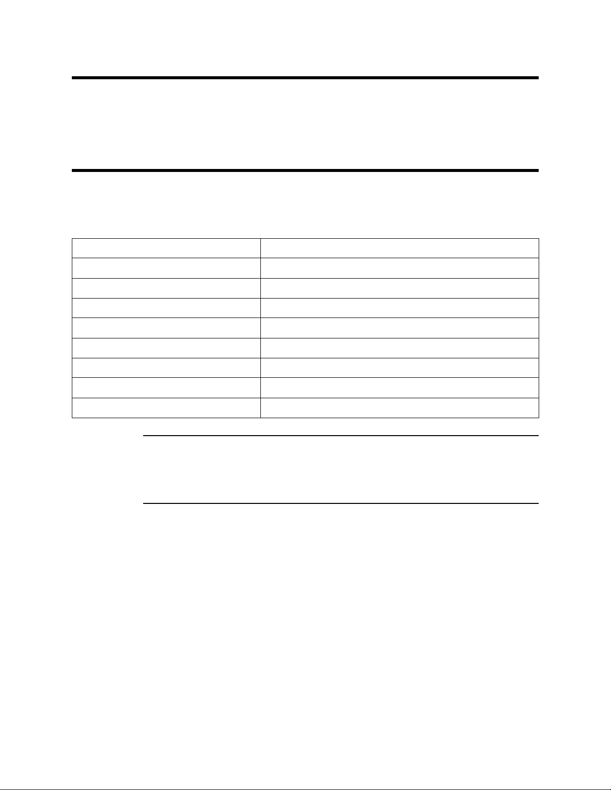
Table 1 lists specifications for the GD-70D4H-XX.
Table 1: Specifications
Target Gas & Detector Range Refer to the RKI Instruments Inc. List of Detectable Gasses
Enclosure Type NEMA 4X
Sampling Method Sample-draw
Input Power 115/220 VAC
Signal Output 4 to 20 mA
Response Time 90% in 60 seconds
Accuracy See GD-70D manual
Flow Rate Approximately 0.5 liters/minute
Recommended Sample Tubing 1/4” O.D. x 1/8” I.D. Teflon PTFE
WARNING: When using the GD-70D4H-XX, you must follow the instructions and
warnings in this manual to assure proper and safe opera tion of the
GD-70D4H-XX and to minimize the risk of personal injury. Be sure to
maintain and periodically calibrate the GD-70D4H-XX as described in this
manual.
1 • Model GD-70D4H-XX Sampl e Draw Transmi tter
Page 5

Description
Exhaust Fitting
Tubi ng St ub
Inlet Fitting
100-240 VA C
H GN
3/4" Conduit
Hub, 2X
Horn/Strobe
GD-70D Detector
NEMA 4X Enclosure
( Cover not sho wn)
AC in T erminal
Power Supply
This section describes the components of the GD-70D4H-XX. It consists of the enclosure, a
GD-70D and a power supply mounted inside, and a horn/strobe mounted on the top
right side of the enclosure. The “XX” in the part number r epr esents a number that den otes
the target gas and changes depending on the target gas. The “H” denotes that the unit
runs from AC power and that a horn/str obe is installed. For example, the part number fo r
a detector head for ozone (O
) detection is GD-70D4H-O3. Consult RKI Instru ments, Inc.
3
for a complete list of available part numbers.
A hydrophobic sample filter is also provided with the GD-70D4H-XX for insta llation at
the inlet fitting. The filter has push fittings for 1/4 i nch O.D. teflon tubing and can be
connected to the short tubing stub on the GD-70D4H-XX inlet fitting. The filter scrubs
particulates out of the sample stream and keeps water and many other liquids from
entering the GD-70D4H-XX flow system.
Figure 1: Component Location
Model GD-70D4H-XX Sample Draw Transmitter • 2
Page 6

Enclosure
Front Farrule
1/4" Tefl on Tube
O-ring
Nut
1/4" Tefl on Tube
Back Farrul e
Fitti ng Body
The enclosure is a type NEMA 4X plastic enclosure designed for use in areas that are
subject to rain or hosing down. A mounting foot is installed in each corner. Two sample
fittings are mounted on the bottom right of the enclosure and two 3/4” conduit hubs are
mounted to the left of the sample fittings.
Sample Fittings
The inlet fitting is on the bottom right of the enclosure and the exhaust fitting is to the left
of the inlet fitting. The fittings accept 1/4”O.D. x 1/8” I.D. Teflon tubing. The inlet fitting
has a short factory installed tubing stub for use with the hydrophobic filter.
Conduit Hubs
Two 3/4” conduit hubs are located to the left of the sample fittings. They are used for
routing wiring into the enclosure by using conduit or an appropriate cable bushing.
Inlet Fitting Tubing Stub
A short tubing stub comes factory installed in the inlet fitting. It is used for connecting the
hydrophobic filter. If the hydrophobic filter is not used, or if you install the hydrophobic
filter in a different location, the tubing stub needs to be removed and replaced with
tubing. Do not pull the tubing stub downward to remove it. Instead, unscrew the lowe r
inlet fitting nut from the fitting body. The tubing stub should come out with the nut. Be
careful not to lose the O-ring that may come out with the tubing stub. Push the tubing
stub up and out of the inlet fitting nut being careful not to lose the ferrule set. Push the
new tubing up through the inlet fitting nut and replace the ferrule set and the O-ring, if it
came out, in the orientation shown in Figure 2. Screw the inlet fitting nut back onto the
fitting body and push the tubing upward until it stops. See Figure 2 for the inlet fitting
layout.
Figure 2: Inlet Fitting with Tubing Stub
3 • Model GD-70D4H-XX Sampl e Draw Transmi tter
Page 7

Installation
GD-70D & Power Supply
The GD-70D sample draw detector head is mounted to a plate inside the enclosure. The
GD-70D sample fittings are factory connected to the sample fittings on the NEMA 4X
enclosure. The GD-70D is powered with 24 VDC supplied by a power supply that
operates from a 100 - 240 VAC input. The GD-70D is factory wired to the power supply
and to the horn/strobe. See the GD-70D operator’s manual for a complete description of
the GD-70D.
Horn/Strobe
A red horn/strobe is installed on the top right side of the enclosure. The GD-70D retains
its NEMA 4X rating with the horn/strobe installed. It is factory wired to the alarm 1 relay
terminals on the GD-70D and the 24 VDC output of the power supply so that it turns on
during an alarm 1 c ondition.
This section describes how to install the GD-70D4H-XX at the monitoring site.
Mounting the GD-70D4H-XX
1. Select a mounting site that is representative of the monitoring environment. Consider
the following when you select the mounting site.
• Select a site that is easily accessible for servicing.
• Select a site where the GD-70D4H-XX is not likely to be bumped or disturbed.
Make sure there is sufficient room to make wiring and sample line connections at
the bottom of the GD-70D4H-XX. Also make sure there is sufficient room to
perform start-up, maintenance, and calibration procedures.
• Select a site near the sampling area. The GD-70D4H-XX is designed to detect a
variety of toxic gases many of wh ich are easily absorbed in sample tubing. Keep
the sample line length to a minimum. Teflon PTFE tubing is recommended.
• Use four 1/4” screws through the mounting feet to mount the GD-70D4H-XX to a
vertical surface. See Figure 3 for the mounting dimensions.
Model GD-70D4H-XX Sample Draw Transmitter • 4
Page 8

NOTE: All Dim enions
Shown i n Inches
Inlet Fitting
8.22
2.51
Exhaust Fit ting
3/4" C onduit
Hub, 2X
9.88
7.01
1.43
8.40
4.83
8.00 MAX
11.75
11.23
Tubing S tub
0.85 M AX
Ø . 34, 4X
Figure 3: Outline & Mounting Dimensions
Connecting Sample Lines to the GD-70D4H-XX
1. Connect the hydrophobic filter to the tubing stub on the inlet.
If the hydrophobic filter is not used, or if you install the hy drophobic filter in a
different location, replace the tubing stub with 1/4’’ x 1/8’’ tubing as described in
“Inlet Fitting Tubing Stub” on page 3.
2. Connect a length of sample tubing to the other side of the hydrophobic filter and route
it to the sampling area. If the hydrophobic filter is not used, or if you install the
hydrophobic filter in a different location, route tubing from inlet fitting to sample
area. Be sure to keep the length to a minimum. Consult RKI Instruments, Inc. for
lengths of more than 20 feet.
CAUTION: Avoid loops or slumps in the incoming sample line. T o r educe response time, keep the
incoming sample line as short as possibl e.
3. Install 1/4“ O.D. x 1/8” I.D. Teflon PTFE sample tubing to the gas out fitting. Route
5 • Model GD-70D4H-XX Sampl e Draw Transmi tter
Page 9

the opposite end of the tubing to an open area where the sample can safely disperse or
1234567
++
--
ALM1DC24V 4-20mA
ALM2 FAULT
+
-
-
+
GD-70D Terminal Strip
89
10
From
Power
Supply
Alarm
Device
Alarm
Device
(+) H
AC Termi nal Str i p
Strobe
Light
100-240 VAC
HNG
4 - 20 mA In (FB)
- (DC Ground)
Controller
(-) N
External Power
Source
+ (No Connection)
(+) H
(-) N
External Power
Source
to an exhaust duct.
Wiring the GD-70D to a Controller and AC Power
WARNING: Always verify that power to the GD-70D4H-XX and to the controller are
off and that the controller’s and GD-70D’s power sw itches are in the off
position before making wiring connections or adjustments.
1. Turn off power to the controller an d the GD-70D4H-XX.
2. Place the controller’s and GD-70D’s power switches in the OFF position.
3. Use the conduit hubs at the bottom of the GD-70D4H-XX for routing power and
signal cables into the enclosure. Route a 3-wire power cable (18 AWG) and any relay
wiring through one conduit hub, and 2-conductor shielded cable, or two wires in
conduit through the other conduit hub to minimiz e crosstalk.
4. If shielded cable is used for controller wiring, connect the signal cable shield’s drain
CAUTION: Leave the cable shield’s drain wire insulated and disconnected at the
Figure 4: External Wiring
wire to a chassis ground at the controller, but do not connect it at the GD-70D4H-XX.
GD-70D4H-XX. You will connect the opposite end of the cable shield’s drain wire at
the controller.
Model GD-70D4H-XX Sample Draw Transmitter • 6
Page 10

CAUTION: At the controller, do not route power and GD-70D wiring through the same conduit
GD-70D mounting bracket
BLK
RED
N L +V -V
Power
Supply
Terminal
(AC)
FAULTALM 2ALM 14-20mADC 24V
--
++
GRN
WHT
BLK
GRN
H N G
AC in
Terminal
RED
Horn/Strob e
BLK
BLK
hub. The power c able may disrup t the transmissi on of the GD-70D’s signal to the
controller.
5. Factory wiring is shown below in Figure 5.
Start Up
Figure 5: Factory Wiring
1. Turn on power to the controller.
2. Turn on the controller.
3. Turn on power (100 - 240 VAC) to the GD-70D4H-XX.
4. Turn on the GD-70D. See the GD-70D Operator’s Manual for GD-70D startup
instructions.
7 • Model GD-70D4H-XX Sampl e Draw Transmi tter
Page 11

Operation
Push Up Here
Captive
Screw
Push Out
Top
Base
See the GD-70D Operator’s Manual for an operational description of the GD-70D that is
mounte d inside the enclosure.
Maintenance/Calibration
GD-70D Maintenance and Calibration
See the GD-70D Operator’s Manual for maintenance and calibration instructions. Use the
inlet fitting on the NEMA 4X enclosure to apply gas instead of the fittin gs inside the
enclosure on the GD-70D.
Adjusting Horn/Strobe V olume
The horn volume on the horn/strobe can be adjusted by doing the following:
1. Turn off the GD-70D. See the GD-7 0D Operator’s Manual for instructions.
2. Tu rn off power (100 - 240 VAC) to the GD-70D4H-XX.
3. Loosen the captive screw at the bottom front of the horn/strobe.
4. Grasp the top and bottom of the horn/strobe and push up and out in order to remove
the cover.
Figure 6: Top Case Remova l
Model GD-70D4H-XX Sample Draw Transmitter • 8
Page 12

5. Turn the cover over and locate the Audio Select switch at the top of the cover as
Audio Select Switch
AUDIO
SELECT
6
Strobe Brightness Switch
(DO NOT ADJUST)
1
2
3
4
5
CANDE LLA S ELE CT
shown in the figure below.
Figure 7: Horn/Strobe Cover
Parts List
6. The Audio Select switch can be set at any number between 1 and 6. Numbers 1-3 all
produce an intermittent buzzing sound with 1 being the loudest and 3 being the
quietest. Numbers 4-6 all produce a steady buzzing sound with 4 being the loudest
and 6 being the quietest. The factory setting is 2.
7. Turn the Audio Select switch so that the selection arrow is pointing to the desired
number.
8. Place the cover over the base and push in and down in order to reinstall the cover.
Make sure that the cover is sealed to the base by the gasket.
9. Screw the captive screw at the bottom front of the horn/strobe back in.
10. Turn on power (100 - 240 VAC) to the GX-70D4H-X X.
11. Turn on the GD-70D. See the GD-70D Operator’s Manual for instructions.
Table 4 lists replacement parts and accessories for the GD-70D4H-XX.
Table 2: Parts List
Part Number Description
06-1273RK 1/4” O.D. x 1/8” I.D. Teflon PTFE tubing
17-4820RK Sample fitting, 1/4” tube bulkh ead union
18-0107RK 3/4” conduit hub
49-0108RK Power Supply, 24 VDC
51-0096RK Horn/strobe, 10 - 33 VDC, NEMA 4X
80-0226RK Hydrophobic filter with push fittings for 1/4 inch O.D. tubing
9 • Model GD-70D4H-XX Sampl e Draw Transmi tter
 Loading...