

Page 1

Install guide 8022
OFF
HEAT COOL
FAN
AUTO ON
Customer Support: 888-515-2585 or Visit our website www.ritetemp.biz
Page 2

Install guide 8022
To avoid electrical shock and to prevent damage to the furnace, air conditioner,
Caution
and thermostat, disconnect the power supply before beginning work.
This can be done at the circuit breaker, or at the appliance.
PG
1
Tools
You will need #1 Phillips screwdriver (small) and
Drill with 3/16-in. (4.8mm) bit for this installation.
1 Location
On replacement installations, mount the new thermostat in place of the
old one if possible.
On new Installations, follow the guidelines listed below.
Locate the thermostat on an inside wall, about 5 ft. (1.5m) above the
floor, and in a room that is used often.
Do not install it where there are unusual heating conditions, such as: in
direct sunlight; near a lamp, radio, television, radiator register, or
fireplace; near hot water pipes in a wall; near a stove on the other side
of a wall.
Do not locate in unusual cooling conditions, such as: on a wall separating
an unheated room; or in a draft from a stairwell, door, or window.
Do not locate in a damp area. This can lead to corrosion that will shorten
thermostat life.
Do not locate where air circulation is poor, such as: in a corner or an
alcove; or behind an open door.
Do not install the unit until all construction work and painting has been
completed.
This thermostat does not require leveling.
Good
C A U T I O N
Your thermostat is a precise instrument.
Please handle it with care.
Turn off electricity to the appliance before installing or
servicing thermostat or any part of the system. Do not
turn electricity back on until work is completed.
Do not short (jumper) across electric terminals at
5ft.
(1.5m)
control on furnace or air conditioner to test the system.
This will damage the thermostat and void your warranty.
All wiring must conform to local codes and ordinances.
This thermostat is designed for use with 24 volt AC and
millivolt systems. The thermostat should be limited to a
maximum of 1.0 amps; higher amperage may cause
damage to the thermostat.
PG
2
Page 3

PG
2 Remove old unit
Switch electricity to the furnace and air conditioner OFF;
then proceed with the following steps.
Remove cover from old thermostat. Most are snap-on types and simply pull
off. Some have locking screws on the side or front. These must be loosened.
Note the letters printed near the terminals. Attach labels (enclosed) to each
wire for identification.
Read instructions carefully before removing any wiring from existing thermostat. Wires must be labeled
Caution
before they are removed. THERE IS NO STANDARD COLOR CODE. When removing wires from their
terminals, ignore the color of the wires since these may not comply with the standard.
Label the wires one at a time. You must have all the wires labeled before
you proceed. With all wires labeled, remove them from the old unit.
Make sure the wires do not fall back inside the wall. Wind them around a
pencil to keep them from falling.
Loosen all screws on the old thermostat and
remove it from the wall.
Fill wall opening with non-combustible insulation
to prevent drafts.
3
W
G
B
PG
3 Mount the 8022
B
O
RC
C
Separate front from back of unit. Press up on the
catch on bottom of thermostat and swing the body
away from the base, lift up to remove the body from
the base.
Hold the base against the wall, with the wires
coming through the opening below the terminal block.
Position the base for best appearance. If you chose to use the optional Wall
Plate, put it in position before screwing base to wall.
Attach the base to the wall with the
two screws provided.
If you are mounting the base to sheet
rock or if you are using the old
mounting holes, use the plastic
anchors provided. Drill a 3/16in.(4.8mm) hole for the insert at each
screw location, then mount the base.
Thermostat
Base
4
Wall
Plate
G
Y
W
RH
Terminal
Block
HEAT COOL
AN
F
O ON
UT
A
OFF
Page 4

4 Before you Connect Wires
Please follow these guidelines for safe and secure wire connections.
Strip insulation 3/8 in. (9.5mm) from wire ends.
Take care not to damage the labels for each wire in handling.
Connect labeled wires only to a terminal with corresponding letter.
Bend the wire slightly, insert the wire under the contact plate and
tighten the screw down onto the wire.
Do not allow wires to touch each other or parts on thermostat.
Caution
Wires must be routed through the hole in the back plate, below the
terminal block, or they will hit parts on the cover.
Optional Wire Connections
Determine which step-by-step wiring diagram you should use. Make sure your
wires are labeled. This may require you to find the 'other end' connection for each
wire on your heating or air conditioning equipment and read the label there.
If you have a wire marked "C" its connection is optional. If you do connect it the
thermostat will draw power from the C wire and this will extend battery life.
PG
5
5 What Wires Do You Have?
R - Single source power for heat/cool
Note: R connects to both RC and RH using the Orange jumper
RH or 4 - HEATING POWER
RC - COOLING POWER
W - HEATING CONTROL
G - FAN RELAY
C - Common side of Heating Power
Y - COMPRESSOR
O - DAMPER OR CHANGEOVER VALVE (POWERED IN COOL)
B - DAMPER OR CHANGEOVER VALVE (POWERED IN HEAT)
From Furnace
And AC unit
Y
From Furnace
And AC unit
R
or
RH
C
G
C
W
Go To Page 13
PG
6
From Furnace
C
W
Go To Page 11
Y
RH
RC
G
W
Go To Page 14
RH
R
or
From Furnace
Go To Page 12
From single stage
heat pump
C
R
Go To Page 15
G
or R
RH
W
C
Y
O
or
B
G
Page 5
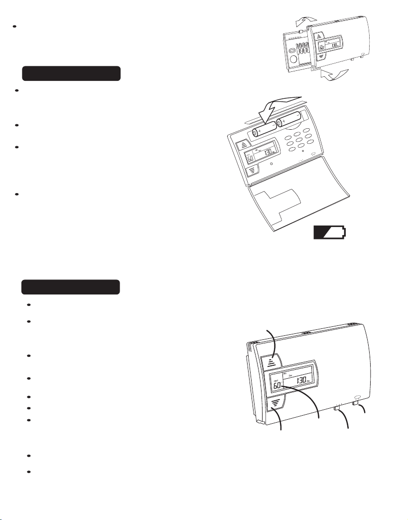
When you have finished making connections. hook
the top of the body onto the base, swing the body
RH
B
O
RC
C
down, and snap the body onto the base.
5 Install Batteries
The 8022 requires batteries to operate
your furnace and retain its programming in
memory.
Switch MODE switch to OFF and
the FAN switch to AUTO.
Remove the front panel battery cover and
install 2 AA alkaline batteries according to
AA
AA
TER
FIL
Y
DA
SPECIAL
ARD
F.W
Y/CLOCK
DA
HOLD
ARD
B.W
RETURN
NEXT
Y
PROG.DA
RESET
O ON
UT
A
OFF
T COOL
HEA
the polarity noted in the compartment.
Initially, all LCD segments will go on.
Press the RESET button to clear transient
program memory.
NOTE: Replace the batteries when this LOW battery
indicator appears on the display or once a year. When
replacing batteries, you have approximately one minute before
your custom program is lost.
6 Check Unit
Follow these procedures to verify you have correctly installed the unit.
To check HEAT mode:
TEMP
UP button
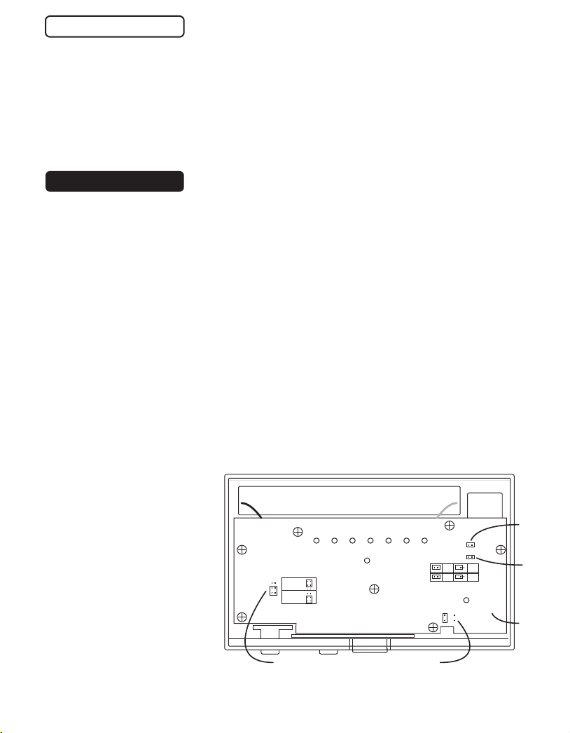
Set the mode switch to HEAT. Set the fan
switch AUTO.
Using the TEMP UP button raise the set point
to 90deg allow the system 5 min to respond.
Verify that heat is blowing from the system.
To check COOL mode:
Set the mode switch to COOL.
Press the TEMP DOWN button to a temp 5
degrees below the room temperature.
Allow the system 5 minutes to respond.
TEMP
DOWN button
Set Temp
Display
Verify that cool air is blowing from the system.
To check Fan: (If you connected the G wire - fan relay)
Switch the FAN switch to the ON position. Verify that air is blowing from
the system. Return to AUTO position for normal operation.
G
Y
W
AN
F
AUTO ON
OFF
T COOL
HEA
FAN
PG
7
AN
F
O ON
AUT
OFF
T COOL
HEA
Fan
Switch
Mode
Switch
PG
8
Page 6
6 Check Unit cont.
Note:
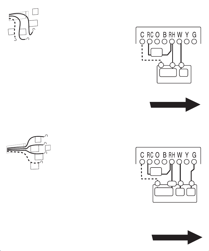
If you have an electric furnace system and the blower does
not operate after installation, remove the thermostat, turn it
over, and find the electric/gas heat selector jumper on the
back of the control unit. Switch it to "Elect"(see Diag below).
Congratulations, you have successfully installed your unit. Please
proceed to the OPERATING Guide to initialize the new thermostat.
7 Power Options
1) The 8022 can run on batteries only. (2AA Alkaline) 24VAC and MV
The batteries will last well over 1 year. If the batteries are not replaced the
thermostat will stop working. Use the MV/C power jumper position.
PG
9
Note:
PG
10
2) The 8022 can run on the C wire if available.
24VAC ONLY
As shown in the wiring diagrams, The C wire is the other side of the 24VAC
heating transformer. If the C wire is used, the batteries are then for AC power
loss only and will last much longer. The thermostat will continue working if the
batteries die. Use the MV/C power jumper position.
FOR ADVANCED USERS ONLY FOR ADVANCED USERS ONLY
3) The 8022 can run on 24VAC series power. 24VAC ONLY
Power for the thermostat comes from the W and RH wires. The batteries are
then for AC power loss only and will last much longer. The thermostat will
continue working if the batteries die. Use the FURN power jumper position.
To locate the Power Mode
Rear View of control unit
Jumpers. Remove the
control unit from the wall
mount, turn it over, and
locate the jumper. It is set
at the factory on MV/C.
Change it from MV/C to
FURN to use series
power.
This option works with
24VAC, .1 to 1 amp.
systems only. Verify
operation. If it doesnt work
FURN
MV/C
Power Mode
jumper
GAS ELECT
Gas - Electric
jumper
24
12
o
o
C
F
12/24hr
jumper
o
C -oF
jumper
Circuit
Board
go back to options 1 or 2 above.
Page 7
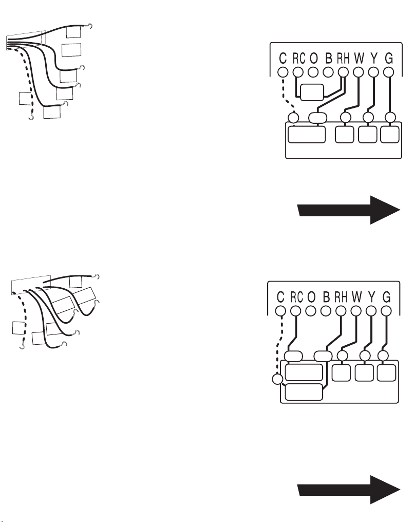
From Furnace
C
W
R
STEP 1 - Connect the R (or RH) wire to
or
the RH terminal on the thermostat.
RH
This connects the Heater Power to the
thermostat.
2 WIRE Heating
(GAS MILLIVOLT or 24vac
Thermostat
PG
11
From Furnace
STEP 2 - Connect the W wire to the W
terminal on the thermostat.
This connects the heater control line to the thermostat.
Your Heater is now connected to the thermostat.
NOTE: Wires marked with the dotted line are optional.
STEP 1 - Connect the R (or RH) wire
to the RH terminal on the thermostat.
G
RH
W
This connects to the Heater Power .
or R
STEP 2 - Connect the W wire to the
W terminal on the thermostat.
C
This connects the heater control line
to the thermostat.
STEP 3 - Connect the G wire to the G
terminal on the thermostat.
This connects the Fan to the thermostat.
jumper
wire
R
C
HEAT
Power
FURNACE
W
HEAT
Return To Page 7
3 WIRE
Thermostat
jumper
wire
W G
RH
C
Heat
Power
FURNACE
Heat
FAN
PG
12
Your system is now connected to the thermostat.
NOTE: Wires marked with the dotted line are optional.
Return To Page 7
Page 8
From Furnace
and AC unit
STEP 1 - Connect the Y wire to the
Y
Y terminal on the thermostat. This
RH
or
R
C
G
W
connects to the Cooler compressor.
STEP 2 - Connect the RH or R wire
to the RH terminal on the thermostat.
This connects the Heater/Cooler
Power.
STEP 3 - Connect the W wire to the W terminal on the
thermostat. This connects to the heater control line.
STEP 4 - Connect the G wire to the G terminal on the
Thermostat. This connects to the Fan.
Your HVAC system is now connected to the thermostat.
4 WIRE
jumper
wire
RH
C
Heat
Power
HVAC SYSTEM
W
Heat
Return To Page 7
Thermostat
Y
Cool
Comp
G
FAN
PG
From Furnace
and AC unit
C
NOTE: Wires marked with the dotted line are optional.
13
STEP 1 - Remove the orange
Y
RH
RC
G
W
Jumper wire.
STEP 2 - Connect the Y wire to
the Y terminal on the thermostat.
This connects to the Cooler
compressor.
STEP 3 - Connect the RH wire to the RH
terminal on the thermostat. This connects to the
Heater Power .
C
STEP 4 - Connect the RC wire to the RC terminal on
the thermostat. This connects to the Cooling Power .
STEP 5 - Connect the W wire to the W terminal on the thermostat.
This connects to the heater control line.
STEP 6 - Connect the G wire to the G terminal on the Thermostat.
This connects to the Fan.
Your HVAC system is now connected to the thermostat.
PG
14
NOTE: Wires marked with the dotted line are optional.
5 WIRE
Remove
jumper
wire
W
COOL
Power
HEAT
Power
RHRC
HVAC SYSTEM
Heat
Y
Cool
Comp
Return To Page 7
Thermostat
G
FAN
Page 9
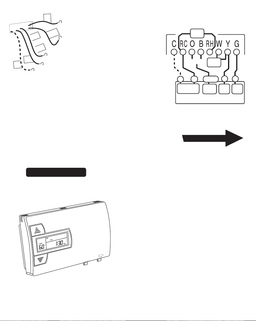
From Furnace
and AC unit
R
C
G
O
or
B
STEP 1 - Connect the G wire to the G
terminal on the thermostat.
This connects the Fan.
Y
STEP 2 - Add a jumper wire between
W and Y.
STEP 3 - Connect the Y wire to the Y
terminal on the thermostat.
This connects the Compressor.
STEP 4 - Connect the O or B wire to the O or B terminal
on the thermostat. (If you have both O and B contact
Ritetemp or your local HVAC contractor for further help)
SINGLE STAGE
HEAT PUMP
C
24VAC
Power
Single Stage HEAT PUMP
This connects the change over valve.
STEP 5 - Connect the R wire to the RC terminal on the Thermostat.
This connects to the 24vac power.
Your HVAC system is now connected to the thermostat.
PG
15
NOTE: Wires marked with the dotted line are optional.
Return To Page 7
8022 Features
The 8022 can be used with most 24 volt gas, oil or electric heating and air conditioning systems, singlestage heat pumps or gas millivolt heating systems. It cannot be used with 120 volt heating systems or
multistage heat pumps. Ask The Home Depot for other thermostats to control those systems.
The 8022 is programmable. There are four programming periods
per day. Each period can be programmed separately.
You can use the built-in time/temperature programs, or alter them
to suit your schedule.
The 8022 separately programs Weekdays, Saturday, and Sunday
- for both heating and cooling.
You can easily override the programmed temperatures for as little
as one programming period or for an entire vacation.
AN
F
O ON
AUT
PG
16
OFF
T COOL
HEA
Temperature swing adjustment lets you fine-tune your system for maximum comfort and energy
efficiency.
A 4-minute minimum off time in COOL protects your air conditioning system from being damaged.
Two "AA" batteries (not included) are used to retain your time and temperature programs, and to
run the thermostat.
A large liquid crystal display shows time, day of the week, room
and set temperatures. It will also remind you when the filter
should be changed in your blower.
jumper
wire
O or B
R
jumper
wire
O or B
Change
Over
Thermostat
Y
Comp
G
FAN
 Loading...