

Page 1
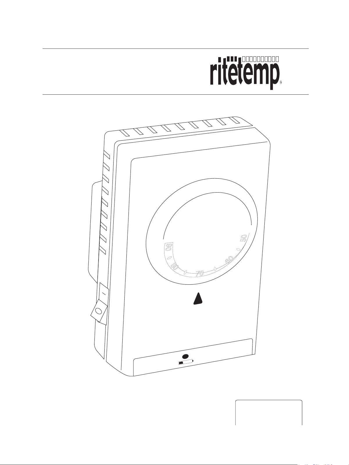
Install Guide 6004
.
ON
.
OFF
ENGLISH
Page 2
Install Guide 6004
To avoid electrical shock and to prevent damage to the heating system,
Caution
and thermostat, disconnect the power supply before beginning work.
This can be done at the circuit breaker, or at the appliance.
Tools
You will need #1 Phillips screwdriver (small)
Location
.
On replacement installations, mount the new thermostat in
place of the old one.
.
On new Installations, follow the guidelines listed below.
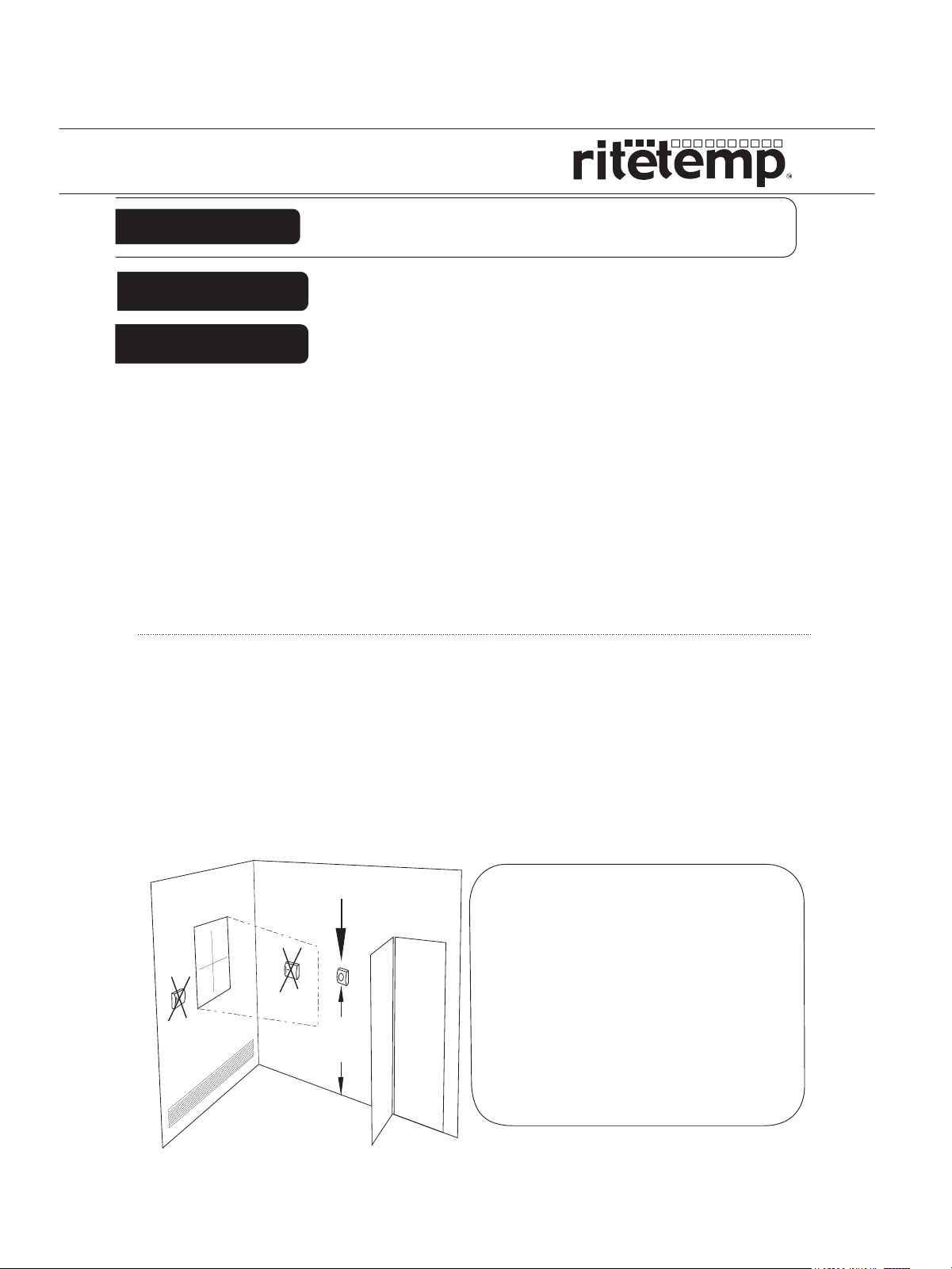
Locate the thermostat on an inside wall, about 5 ft. (1.5m)
above the floor, and in the room where the heater is situated.
.
Do not install where there are unusual heating conditions, such
as: in direct sunlight; near a lamp, radio, television, or above
the baseboard heater, or fireplace; near hot water pipes in a
wall; or any other heat source.
.
Do not locate in unusual cooling conditions: in a draft from a
stairwell, door, or window; or on the wall of an unheated room.
.
Do not locate in a damp area. This can lead to corrosion that
will shorten thermostat life.
.
Do not locate where air circulation is poor, such as: in a corner
or an alcove; or behind an open door.
.
Do not install until completion of construction and painting.
.
This thermostat does not require leveling.
PG
1
Good
5ft.
(1.5m)
C A U T I O N
.
Your thermostat is a precise instrument. Please
handle it with care.
.
Turn off electricity to the appliance before installing or
servicing thermostat or any part of the system. Do not
turn electricity back on until work is completed.
.
Do not short (jumper) across electric terminals at
furnace control to test the system. This will damage
the thermostat and void your warranty.
.
All wiring must conform to local codes and ordinances
Wiring must come through, and the thermostat
mounted on a standard approved electrical junction
box.
.
This thermostat is designed for use with 120-220 volt
AC systems. The thermostat should be limited to a
maximum of 16.0 amps; higher amperage may cause
damage to the thermostat.
PG
2
Page 3
Remove old unit
.
Switch electricity to the heater OFF at the circuit breaker;
then proceed with the following steps.
.
Remove cover from old thermostat. Most are snap-on types and
simply pull off. Some have locking screws on the side or front.
These must be loosened to remove cover.
.
Remove the old unit from the terminal box, by unscrewing the
captive screws.
Make sure you note which wire is which when
Caution
.
On your new thermostat, separate
Control Unit (front) from Wall Unit (back).
.
Grasp the front of the unit and the back of
the unit and gently pull the thermostat body
away from the base.
you disconnect the old thermostat. Use only
UBC approved wire nuts to connect wires.
Connect wires
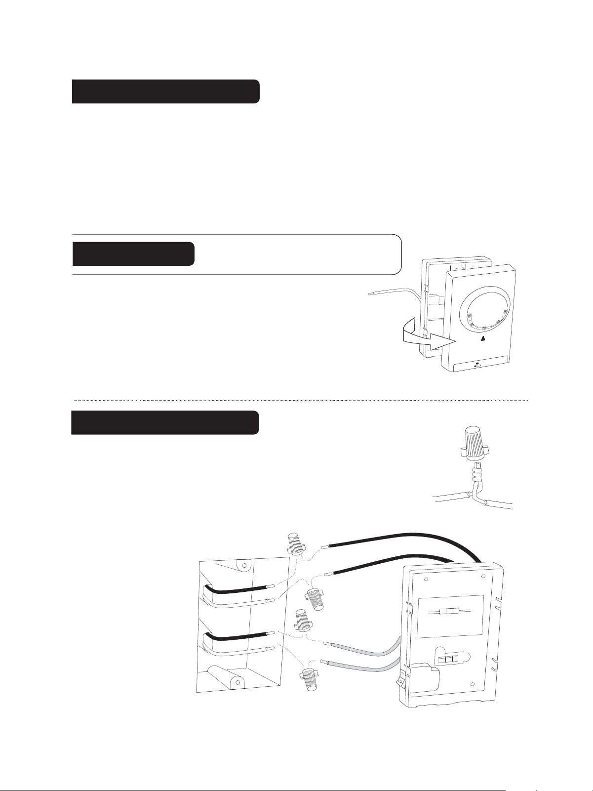
If you have 4 wires (Double Pole), inside the wall box,
follow these wiring instructions.
.
Connect the LOAD to the RED wires (T1, T2)
and the LINE to the BLACK wires (L1, L2).
.
Twist wires together first, then secure by twisting
wire nut on.
.
Push the wires and
wire nuts
into the
terminal
box.
LINE
LOAD
L1
T1
BLACK
BLACK
L2
RED
RED
T1
T2
O LOAD
T
CAUTION HIGH VOL
DISCONNECT
BEFORE SER
T
A
ST
POWER SUPPL
VICING
BLACK
O LINE
T
AGE!
T
PG
3
L1
L2
Y
Junction box in wall
T2
RED
PG
4
Page 4
Connect wires cont.
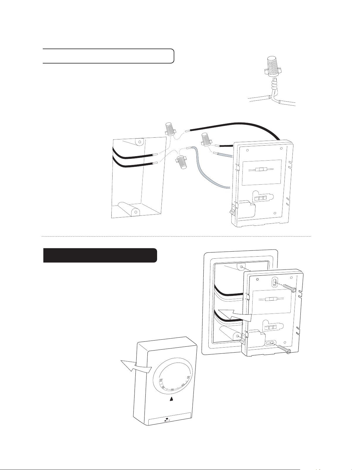
If you have 2 wires (Single Pole) inside the wall box,
follow these wiring instructions.
.
Connect the LOAD to the RED wire (T1)
and the LINE to the BLACK wire (L1).
.
Connect BLACK-L2 and RED-T2 from the back of
the thermostat together.
.
Twist wires together
first, then
secure by
O LINE
T
twisting
wire nut on.
.
Push the
TO LOAD
wires and
wire nuts
into the
terminal box.
PG
5
Junction box in wall
L1
BLACK
T1
RED
L2
T2
RED
BLACK
RED
T1
T2
TO LOAD
CAUTION HIGH VOLT
DISCONNECT
BEFORE SER
T
A
ST
POWER SUPPL
VICING
BLACK
O LINE
T
AGE!
L1
L2
Y
Attach Unit
.
Position (optional) wall plate over
junction box.
.
Align the 6-32 captive screws with
the threaded holes in the junction box.
.
Screw the wall unit to the junction
box.
Note: Do not reattach
control unit until batteries
have been inserted.
PG
6
.
.
ON
OFF
ST
RED
TO LOAD
CAUTION HIGH VOL
DISCONNECT
BEFORE SER
T
A
BLACK
TO LINE
AGE!
T
POWER SUPPL
VICING
Y
Page 5
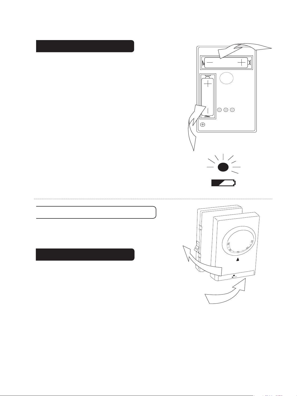
Install Batteries
.
The 6004 requires 2AA batteries.
.
On the control unit, Switch AC POWER
switch to OFF.
AA
.
Install 2 AA alkaline batteries according
to the polarity noted in the compartment.
DO NOT USE Rechargeable Batteries.
Caution: The thermostat will go "off" if the
batteries die. This exposes your house to
unexpected heat or cold and should be
avoided.
NOTE: Replace the batteries when the red
LOW battery LED indicator blinks or once a
year.
Install Batteries cont
.
Replace front of control unit on the
wall unit.
AA
PG
7
.
Check Unit
O N
.
O F F
Follow these procedures to verify
you have correctly installed the
unit.
.
To check HEAT mode:
.
Set the AC POWER switch to ON.
.
Turn TEMP DIAL counter clockwise to its
highest stop. This is the warmest setting. Allow the
system 5 min to respond. Verify that heat is
coming from the system.
.
Return dial to comfortable setting.
PG 8
Page 6
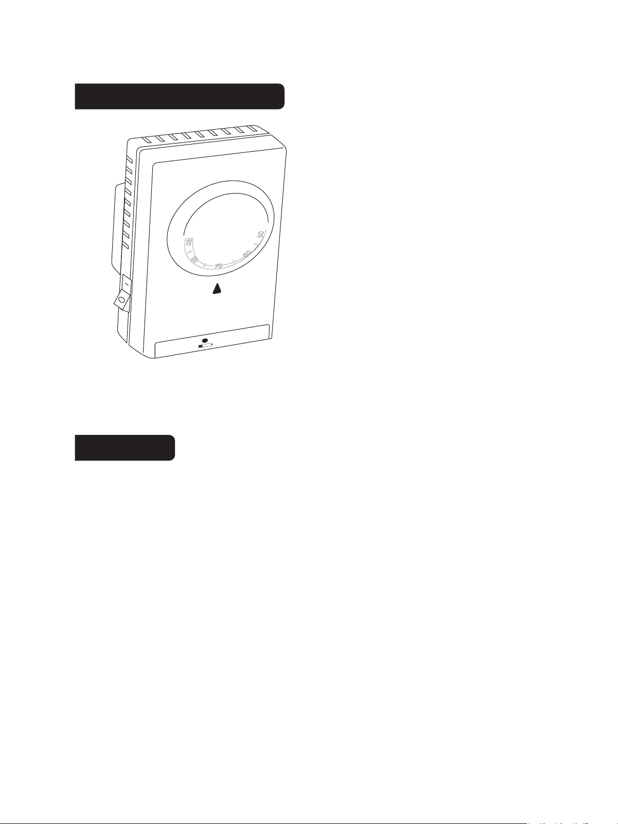
6004 Features
.
ON
.
OFF
The 6004 can be used with
most 120/208/240 volt
electric heating devices. It
provides Line voltage control
for radiant cable, electric
baseboard, and wall heaters
within the ratings listed.
Electrical Rating 120/208/240 Vac;
16A max load
PG
9
Notes
PG
10
Page 7
or V
.
ON
.
OFF
Customer Support: 877-505-2353
isit our website www
Printed in China
.ritetemp-thermostats.com
161
1-004
 Loading...