

Page 1
Wireless
Receiver
(Compatible with ProSYS,
WaveSYS & Orbit-Pro systems)
United Kingdom
Tel: +44-161-655-5500
technical@riscogroup.co.uk
Italy
Tel: +39-02-665-90054
support@riscogroup.it
Spain
Tel: +34-91-490-2133
support-es@riscogroup.com
France
Tel: +33-164-73-28-50
support-fr@riscogroup.com
Belgium
Tel: +32-2522-7622
support-be@riscogroup.com
For RP128EW0800A or RP128EW1600A only.
USA
Tel: +305-592-3820
support@riscogroupusa.com
Brazil
Tel: +55-11-3661-8767
support-br@riscogroup.com
China
Tel: +86-21-52-39-0066
support-cn@riscogroup.com
Poland
Tel: +48-22-500-28-40
support-pl@riscogroup.com
Israel
Tel: +972-3-963-7777
support@riscogroup.com
WARRANTY
RISCO Group and its subsidiaries and affiliates ("Seller") warrants its
products to be free from defects in materials and workmanship under
normal use for 24 months from the date of production. Because Seller
does not install or connect the product and because the product may be
used in conjunction with products not manufactured by the Seller, Seller
can not guarantee the performance of the security system which uses
this product. Sellers obligation and liability under thiswarranty is expressly
limited to repairing and replacing, at Sellers option, within a reasonable
time after the date of delivery,any product not meeting the specifications.
Seller makes no other warranty, expressed or implied, and makes no
warranty of merchantability or of fitness for any particular purpose. In no
case shall seller be liable for any consequential or incidental damages
for breach of this or any other warranty, expressed or implied, or upon
any other basis of liability whatsoever. Sellers obligation under this
warranty shall not include any transportationcharges or costs of installation
or any liability for direct, indirect, or consequential damages or delay.
Seller does not represent that its product may not be compromised or
circumvented; that the product will prevent any personal;injury or property
loss by burglary, robbery, fire or otherwise; or that the product will in all
cases provide adequate warning or protection. Buyer understands that
a properly installed and maintained alarm may only reduce the risk of
burglary, robbery orfire without warning, but is not insurance or a guaranty
that such will not occur or that there will be no personal injury or property
loss as a result. Consequently seller shall haveno liability for any personal
injury, property damage or loss based on a claim that the product fails
to give warning. However, if seller is held liable, whether directly or
indirectly, for any loss or damage arisingfrom under this limited warranty
or otherwise, regardless of cause or origin, sellers maximum liability shall
not in any case exceed the purchase price of the product, which shall
be complete and exclusive remedy against seller. No employee or
representative of Seller is authorized to change this warranty in any way
or grant any other warranty.
W
ARNING: This product should be tested at least once a week.
© RISCO Group 12\08 5IN128EW D
Introduction
The Wireless Receiver provides wireless zone expansion to the
ProSYS, WaveSYS and Orbit-Pro panels. It also supports the
wireless rolling code transmitters. The Wireless Receiver is
available in either 8 or 16 zone modules with both modules
supporting up to 8 "rolling-code" 4-button transmitters.
Main Features:
Super heterodyne technology
Programmable supervision time
Detection of Transmitter’s low battery condition
Tamper detection
Signal jamming indication
Threshold level calibration
Nominal center frequency: 868.65 MHz or 433.92 MHz
Receiving Signal StrengthIndication
LED Indicators
The Power LED on the receiver indicates the system operation
as follows:
Condition
ON
OFF
RAPID FLASH
(about 4 times
per second)
SLOW FLASH
(about once
every 2 seconds)
Description
The receiver is operating properly
The receiver is inoperative due to lack of power
Indicates an acknowledge to a
transmitter’s signaling.
Indicates the system is in Programming and
Installation mode or communication with the
bus is interrupted or an undefined module is
connected to the bus.
Tamper Detection
The Wireless Receiver has a tamper input and a tamper switch
to indicate box or wall tamper.
To use the Wall tamper switch open the knockout hole located in
the center of the receiver’s back cover.
Zone Expansion
Wireless and hardwired expansion boards may be added anywhere
along the bus. (Up to 120 wireless zones can be added to the
ProSYS).
The wireless zones can be programmed to have any of the
characteristics of a wired zone with the exception of Zone
Termination (which will be set to Wireless) and Loop Response
(LCD message will be “none”). For more information on the zones
features refer to the ProSYS/Orbit-Pro Installation and
Programming Manual.
When the receiver is used as a zone expander, the receiver’s
principle tasks are:
Receiving and decoding of incoming signals
Wireless zone allocation
Maintain transmitter supervision
Detect jamming
Wireless Zone and Module Reporting Characteristics
‘Rolling code’ Key-Fob
Transmitters
Each wireless zone expander can support 8 ‘rolling code’
transmitters with a total of 32 transmitters in the system (4 wireless
buttons expansions). Each rolling code transmitter has 4 buttons
with the following options: ARM, DISARM, PANIC, and UTILITY
OUTPUT activation. When the ‘Key-Fob” is used the receiver
decodes rolling-code signals in order to perform the key’s operation.
Installation
Mounting the Wireless Receiver
When mounting the Wireless Receiver the following considerations
are relevant:
1. Do not install the Wireless Receiver close to metal objects
and RF generating devices such as TV sets or computers.
2. Mount the Receiver at a height of at least 1.5 m (5 ft) above
the floor.
3. Mount the Receiver relatively close and central to the
transmitter locations.
Wiring the Wireless Receiver
1. The Wireless Receiver is connected to the Main Panel BUS.
Connect the first four terminals of the receiver to the Main
Panel’s 4 wire Bus as follows:
NOTE:
Use a quality 4- conductor cable with an adequate gauge
size to accommodate any voltage drops which may occur
when multiple modules and long wire runs are employed
(The maximum wire run permitted is 300m/ 1000 feet for all
legs of the BUS)
EXPANSION BUS TERMINALS
AUX COM BUS BUS
Color
RED (Black) (Yellow) (Green)
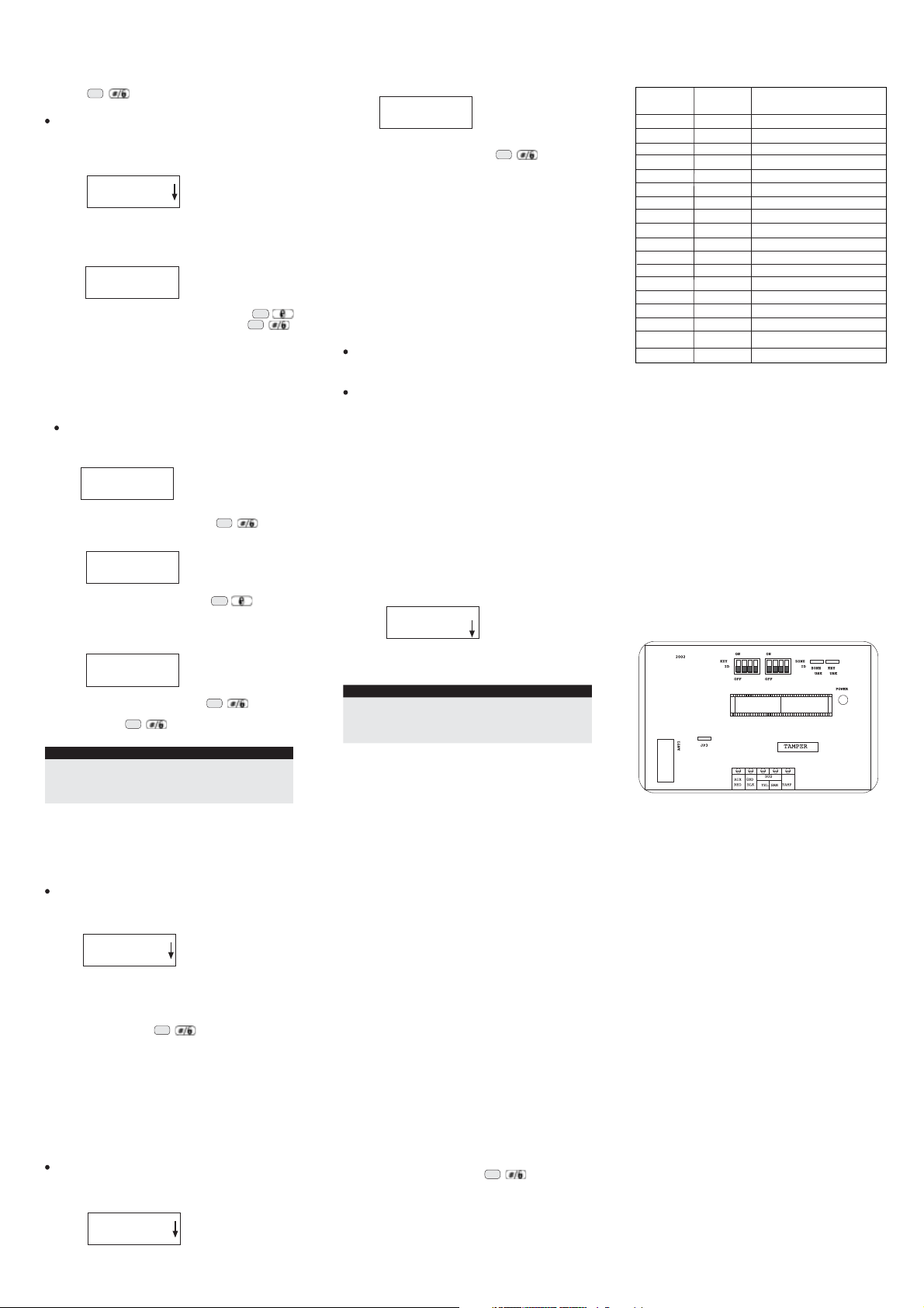
2. TMP terminal: You can use the wireless receiver to detect a
box tamper alarm. Connect a normally close (NC) momentary
action push button switch between the TMP and COM
terminals.
NOTE:
In order to use the TMP input to cause an alarm, at least
one of the tamper switches on the board should be
disconnected.
Jumpers
The Wireless Receiver board contains the following three jumpers:
ZONE USE: Used to select whether the zone expansion
module will be activated.
KEY USE: Used to select whether the ‘Rolling Code‘ Key
module will be activated.
JP3: Determines the receiver’s sensitivity. The jumper must
be placed on both pins for maximum sensitivity and high
level of communication.
The following table determines the receiver’s operating options:
Zone Use
Zone Expander only
‘Rolling Code’ Key
Accessory only
Zone Expander and ‘Rolling
Code’ Key Accessory
Jumper
In
Out
In
Defining the Receiver module’s ID
Defining the receiver module’s ID’s requires the setting of an ID
to the wireless Zone expander and the ‘Rolling Code’ Key
accessory with the Zone ID dip switches and the KEY ID dip
switches. Each module in the receiver must be given a unique
ID, with which it is identified in the system. Use the following
tables to set the dip switches on the PC board.
Key Use
Jumper
Out
In
In
NOTE:
Be sure to set- up the appropriate set of dip- switches (KEY
ID and/ or ZONE ID) according to the designated use.
The ID numbering for the Zone expander and the ‘Rolling
Code’ Key module are independent of each other.
The max Key ID is 04 indicating Max of 32 wireless key
buttons in the system
Zone
Expander ID
01
02
03
04
05
06
07
08
KEY ID
01
02
03
04
OFF
OFF
OFF
OFF
OFF
OFF
ON
ON
ON
ON
ON
ON
1
1
Dip Switches
2
OFF
OFF
ON
ON
OFF
OFF
ON
ON
Dip Switches
2
OFF
OFF
ON
ON
OFF
OFF
OFF
OFF
ON
ON
ON
ON
OFF
OFF
OFF
OFF
4
3
OFF
OFF
OFF
OFF
OFF
OFF
OFF
OFF
3
4
OFF
OFF
OFF
OFF
Programming
Programming the wireless zone expander and the ‘Rolling Code’
Key module consists of five steps:
1. Adding the wireless modules to the system.
2. Calibrating the wireless modules (only on ProSYS &
WaveSYS).
3. Allocating the wireless zones and the wireless rolling code
key buttons.
4. Defining parameters for the wireless zones and the rolling
code key buttons.
5. Performing transmitter communication quality test.
Step 1: Adding the modules
To add a Wireless Zone Expander:
1. From the main Installer programming menu, select [7] for
the Accessories option. The first submenu (ADD/ DEL MDL)
appears:
ACCESSORIES:
1) ADD / DEL MDL
2. Press [1] to access the Add Delete Module menu options.
3. Press [2] to add a zone expansion module. The following
display appears:
ZONE EXPANDER:
ID=1 TYPE=NONE
Status
4. Use the \ or \
over the Zone Expander's ID number to add or delete.
Place the cursor over the TYPE field and use the \
key to toggle between the options to select the required
Zone Expander as follows:
Bypass
keys to position the cursor
Stay
Page 2
WZ08 (an 8 Wireless Zone Expander)
WZ 16 (a 16 Wireless Zone Expander) To confirm your choice
#
Disarm
\
press
To add a Wireless Button Module:
1. From the main Installer programming menu, select [7] for
the Accessories
appears:
option. The first submenu (ADD/ DELMDL)
ACCESSORIES:
1) ADD / DEL MDL
2. Press
to access the Add Delete Module menu options.
[1]
[6] to add a Wireless Button Module. The following
3. Press
display appears:
WL BUTTON MODL:
ID=1 TYPE=NONE
Stay
4. Place the cursor over the
to choose WBT8. To confirm your choice press
field, and press
TYPE
Disarm
\
#
\
Step 2: Calibrating the wireless
module:
Measures the RF noise that the receiver is picking up. This is
used for jamming indication in order to eliminate false jamming
alarms. The range is 00-99.
To calibrate the wireless module:
1. From the ProSYS/WaveSYS
menu, select [2] [9] [5] for the Zones maintenance wireless
module calibration option. The following display appears:
2. Select the wireless zone expander for which you want to
establish the threshold level and press
following display appears, showing the current threshold level:
3. To perform a new calibration, use the key to select
[Y] YES.
4. After the calibration process is finished, the new receiving
threshold is displayed, as follows:
5. To confirm the new threshold, press
-OR- To change the threshold manually, enter the required
level and press
NOTE:
In order ensure that a momentary high noise level (due to
environmental reasons) will not cause a jamming alarm, you
can set the threshold level to be higher than the calibrated
level.
(Only on ProSYS & WaveSYS)
main Installer programming
CHOOSE WL ZE:
1) ID:1 TYP:WZ16
THOLD = XX ZE:1
RE-CALIBRATE? N
Stay
THOLD=XX ZE:1
NEW THOLD = YY
#
Disarm
#
Disarm
\ .
#
Disarm
\ The
\
\
Step 3: Allocating Wireless
Zones and Wireless Key
Buttons:
To allocate a Wireless zone:
1. From the main Installer programming menu, select [2] for
the
option. The following message appears:
Zones
SUBJECT: ZONES
1) ONE BY ONE
2. Press
to access the Zone Maintenance menu options.
[9]
3. Press [6] on the ProSYS/WaveSYS menu or [5] on the OrbitPro menu to access the wireless zones allocation option.
4. Select the zone number intended for the first wireless
transmitter followed by
5. Select the required option, as follows:
[1] to skip to the next transmitter assignment
Press
Press [2] to overwrite the data into the selected location and
allocate the transmitter to a zone. After choosing this option
send a write signal from the transmitter and wait for
confirmation beep.
Press [3] to erase the allocation data in the selected location
and then press [Y] YES or [N] NO to confirm your choice.
Press [4] to choose supervision and then press [1] for
supervised or [2] for unsupervised, to confirm your choice.
To allocate a Wireless Key Button:
1. From the main Installer programming menu, select [8] for
the Miscellaneous option. The following message appears:
MISCELLANEOUS:
1) WL BUTT PARAM
Disarm
#
\ .
2. Press [2] to access the Wireless Button Allocation menu
options. The following display appears:
W BUTT ALOCAT:
BUTT#=01 (1:01)
3. Select the key button number intended for the first wireless
key button transmitter followed by
Disarm
#
\
4. Select the required option, as follows:
[1] to skip to the next key button transmitter assignment
Press
Press
to overwrite the data into the selected location and
[2]
allocate the key button. Send a write signal from the key
button transmitter by pressing on any of the key buttons and
wait for the confirmation beep.
[3]
Press
to erase the allocation data in the selected location
and then press [Y] YES or [N] NO to confirm your choice.
Step 4: Defining Wireless
Zones and Wireless Key
Buttons parameters:
To define Wireless Zone parameters:
To define the wireless zones parameters refer to Zones Menu in
ProSYS Installation and Programming manual
the
.
To define Wireless Key Button parameters:
Each wireless key button consists of 4 keys with the following
options: ARM, DISARM, PANIC, and UTILITY OUTPUT activation.
To define the wireless key buttons refer to the instructions supplied
with the RP128T4RC00A rolling code transmitter or refer to the
ProSYS Installation and Programming manual
.
Step 5: Wireless
communication testing:
Perform a Wireless Communication test to check the
communication between the transmitters and the receiver:
1. From the main Installer programming menu, select
[7] in the ProSYS/WaveSYS menu or [2] [9] [6]
Pro menu for the
following display appears:
Communication Test option. The
Wireless
[2] [9]
in the Orbit-
COMMUN . QUALITY:
001) Z#=XXX :000
2. Perform the transmission from the selected zone. Allow a
few seconds for the receiver to react. The value presented
is a number between 00-99 that indicates the signal strength.
NOTE:
For more successful communication the strength of the signal
should be higher than the RF noise that the receiver is picking
up. If not, it is recommended to relocate the detector or the
receiver or to use a repeater..
For more detailed information, please refer to the
Installation and Programming manual.
ProSYS
Additional Wireless
Programming:
Feature Description
Wireless Module Specifies the period of time that the
jamming time wireless module tolerates
Supervision Time Specifies how often the ProSYS
unwanted radio frequencies capable
of blocking (jamming) signals
produced by the system's
transmitters. The time can be defined
to None or 10, 20 or 30 seconds. If
Audible Jamming is set to YES
the panel will also activate the
external sounder.
checks for supervision signals,
identifying each of thesystem's
transmitters. The range is from
0-7 hours.
0 hours disables supervision.
Note:
It is recommended to set the
supervision time to a minimum of 3
hours
Walk test
Once the installation is finished, perform a walk test and ensure
all the wireless zones are properly covered. To execute a walk
test, do as follows:
1. From the main
[4
] for the
2. Enter your user code and press
3. Press [0] to access the Walk Test option.
4. At the end of the walk test, verify that all wireless zones
responded properly.
User Function Programming
Maintenance option.
Disarm
#
menu, select
\ .
Ordering Wireless P/N:
Part Number
(868.65MHz)
RP128EW0800A
RP128EW1600A
RP128EWR000A
RWT72C86800A
RWT72M86800A
RWT72P86800A
RWT72X86800A
RWT92086800A
RWT92P86800A
RWT32S86800A
RP128T4Z000A
RP128T4RC00A
RWT54086800A
RW140KWL000A
RWT50P86800A
RWT52P86800A
RWT6SW86800A
RWT6FW86800A
Part Number
(433.92MHz)
RP296EW0800A
RP296EW1600A
RP296EWR000A
RWT71EUV2
RWT71EUMV2
RWT71EUPV2
-
RWT90EUV2
RWT90PEU000A
RWT30EUV2
-
RP296T4RC00A
RWT540000EUA
RW140KWL000H
RWT50EUV2
RWT52P43300A
RWT6SW43300A
RWT6FW43300A
Product Description
8 zone wireless expander + 8 key buttons
16 zone wireless expander + 8 key buttons
Wireless repeater
Wireless door contact
Wireless door contact + Magnet
Wireless Universal/Shutter
Dual channel Shutter /Universal
Wireless PIR detector
Wireless PIR + PET detector
Wireless Smoke detector
4 button Zone transmitter
Wireless 4 Button Rolling Code transmitter
3 Channel transmitter
Wireless Keypad
Wireless panic button
Wireless panic button
Wireless shock detector, white casing
Flood detector
Technical Specifications:
Operating Voltage:
Current consumption:
RF immunity:
Operating temperature:
Storage temperature:
Size:
Frequency:
9 to 16 VDC
40 mA
20V/m 80MHz to 1GHz
°
0°
C to 50
-20
°C to 60
145 X 90 X 38 mm
(5.7 X 3.54 X 1.49 inch)
RP128EW0800A – 868.65 MHz
RP128EW1600A – 868.65 MHz
RP296EW0800A – 433.92 MHz
RP296EW1600A – 433.92 MHz
°F to 122°
C (32
°C (-4°F to 140°
F)
F)
 Loading...