

Page 1
Dual Technology Outdoor Detector
Rivelatore da Esterno a Doppia Tecnologia
Detector de Exterior de Doble Tecnología
Détecteur extérieur à double technologie
Detector Externo de Dupla Tecnologia
Dual Technology-Buitendetector
Español Italiano English Nederlands
Français
WatchOUT 315DT
Installation Instructions - Relay & BUS Modes
Istruzioni per l’installazione in modalità Relé e BUS
Instrucciones de Instalación - Modos Relé y BUS
Guide d'installation - Modes Relais et BUS
Instruções de Instalação - Modos Relé & BUS
Relais- & BUS-modusinstallatie-instructies
Português
Page 2
2 WatchOUT 315DT Installation Manual
Page 3

Table of Contents
Relay Mode Installation .......................................................................................................... 4
Introduction ............................................................................................................................. 4
Mounting ................................................................................................................................. 4
Mounting Considerations...................................................................................................... 4
Wall Mount Installation ......................................................................................................... 5
Flat Mounting: ...................................................................................................................... 5
45° angle Mounting (Left side mounting) .............................................................................. 5
Changing Back Tamper position .......................................................................................... 6
Terminal Wiring ....................................................................................................................... 6
DIP Switch Settings .................................................................................................................. 7
Microwave Adjustment ............................................................................................................ 7
Walk test .............................................................................................................................. 7
LEDs Display ............................................................................................................................. 7
Relay Mode / BUS Mode Jumper ............................................................................................. 8
Standard Swivel Installation ..................................................................................................... 8
Wall Mounting ...................................................................................................................... 8
Swivel Conduit Mounting ...................................................................................................... 8
Replacing a Lens .................................................................................................................... 10
Lenses Types..................................................................................................................... 11
Technical Specification .......................................................................................................... 12
Ordering Information ............................................................................................................ 12
UL Compliance Section .......................................................................................................... 12
BUS Mode Installation .......................................................................................................... 13
Introduction ........................................................................................................................... 13
Terminal Wiring ..................................................................................................................... 13
DIP Switch Settings ................................................................................................................ 13
ProSYS Programming ............................................................................................................ 14
New System Parameters ........................................................................................................ 16
English
WatchOUT 315DT Installation Manual 3
Page 4
Relay Mode Installation
Introduction
RISCO Group's Dual Technology Outdoor Detector, WatchOUT 315DT, is a unique detector with
signal processing based on two Passive Infrared (PIR) channels and two Microwave (MW)
channels. The detector can operate as a regular relay detector connected to any control panel, or
as a BUS accessory when connected to RISCO Group's ProSYS control panel via the RS485
BUS, thus having unique remote control and diagnostic capabilities.
The instructions describe herein, describe the WatchOUT 315DT in Relay & BUS mode.
Mounting
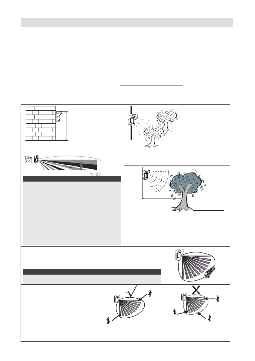
Mounting Considerations
1m - 2.7m
(3'3" - 8'9")
Optional Height: 1m - 2.7m
(3'3"-8'9")
Typical Height: 2.2m (7'2")
Default Lens: Wide angle 15m (50') 90°
(RL300)
Note:
1. For low installations, below 1.7m (5'6") in which
pet immunity is required, use the supplied
RL300F lens (low wall or fence installations).
2. The detector's pet immunity (height of an animal,
no weight limitation), is up to 70 cm (2'4"), when
installing the detector at 2.2m (7'2"). If the
installation is bellow the height mentioned
above, the Pet Immunity decreases accordingly;
every 10 cm (4") decrease in installation height
leads to 10 cm (4") decrease in pet imunity.
If possible, avoid pointing the detector to
moving objects (swaying trees, bushes etc.)
Keep d istance o f
minimum 5m (16')
from moving objects
5m (16')
Ensure any objects do not obstruct the field of
view for both technologies. Pay attention to
growing trees or bushes, plants with big
moving leaves etc
For installations with extensive vehicle traffic or targets beyond
the required detection range, it is recommended to adjust the
MW sensitivity and/or to tilt the detector down.
Note:
Tilting the detector down may reduce the pet immunity
For optimum detection, select a
location that is likely to
intercept an intruder moving
across the coverage pattern at
a 45° trajectory.
Out of
Detection Range
NOTE: Disable Proximity AM during heavy rain (if WatchOUT 315DT is not sheltered) to
prevent Proximity AM alerts.
4 WatchOUT 315DT Installation Manual
Page 5
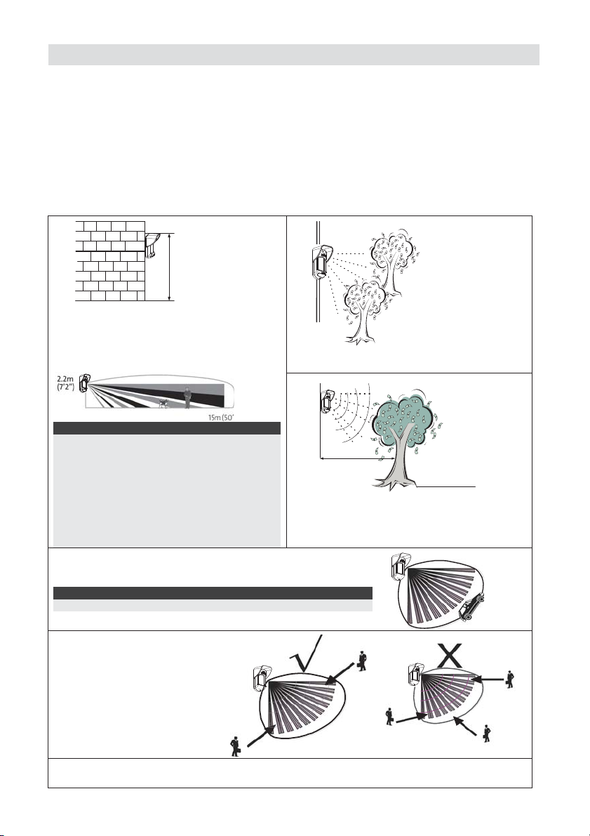
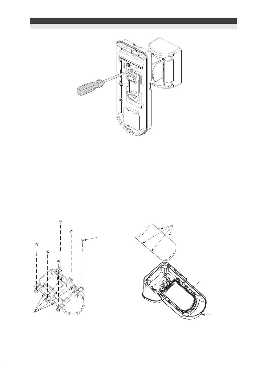
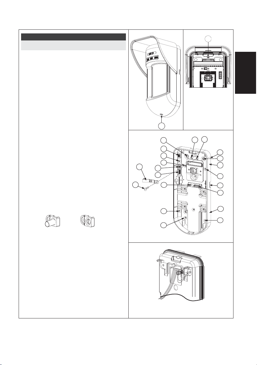
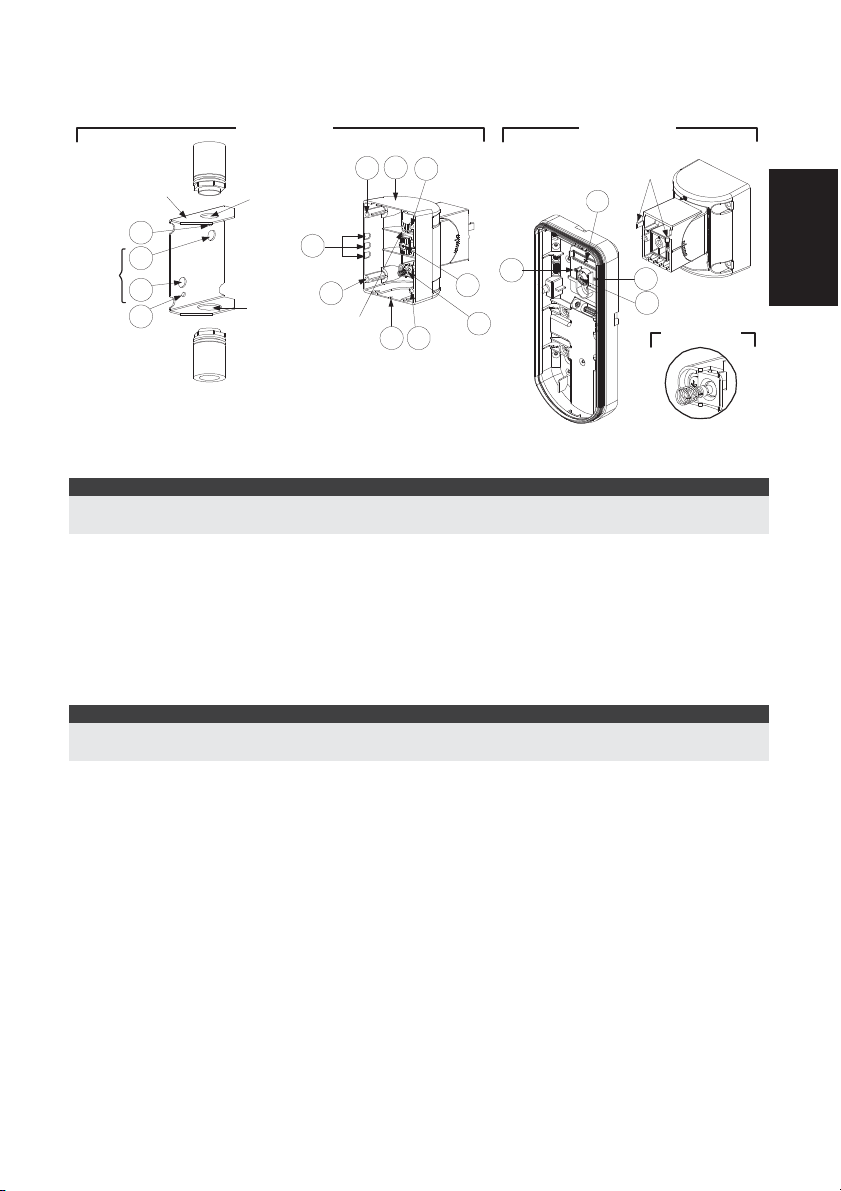
Wall Mount Installation
t
Note:
The installation knockouts numbering are marked on
the back plate.
1. Open WatchOUT front cover
(unlock C1, Figure 1).
2. Release internal base (unlock I1, Figure 2).
3. Select mounting installation as follows:
Flat Mounting:
Open knockouts on external base (Figure 3).
• B1 - B4: Wall mounting knockouts
• T1: Back tamper knockout
• W2 / W3: wires entry knockouts
45° angle Mounting (Left side
mounting)
a. Open knockouts on external base
(Figure 3)
• L1, L2: Left mounting knockouts
• T3: Left tamper knockout
• W5 / W6: Wire entry knockouts
b. Remove tamper spring.
c. Replace tamper bracket (Item 1) with
supplied flat tamper bracket (Item 2).
Item 1
d. Insert Tamper lever B onto T5 and T3
and secure screw A (Figure 3).
4. Insert external wires through external base
W2, W3 (Flat Mounting) or W5, W6 (Left
side mounting) (Figure 3).
5. Secure external base to the wall.
6. Insert external wires and tamper wires
through internal base (Figure4).
7. Secure internal base to external base (lock
I1, Figure2).
8. Close the front cover (Lock C1, Figure1)
after wiring and setting DIP switches.
9. Walk test the detector.
Item 2
Figure 1
Figure 3
Tamper
Lever
B
A
Figure 4
Figure 2
C1
T1
T3
L1
B1
W5
W6
W3
L2
B4
l1
English
T5
T6
T4
T2
R1
(not visible)
B2
W9
W2
R2
(not visible)
B3
Note:
For 45° right side installation use the equivalent units on the external base as follows:
Knockouts Description Lef
Right
Mounting Knockouts L1, L2 R1, R2
Tamper spring knockouts T1,T3 T2,T4
Tamper screw anchor T5 T6
Wiring Knockouts W5, W6 W7, W8
WatchOUT 315DT Installation Manual 5
Page 6
Changing Back Tamper position
fOff
The back tamper is by default secured on the right
side of the internal base (rear view). If you wish to
move it to the left side (rear view), do the following
Figure 5
Left Side
Tamper
6
(Figure 5):
1. Remove tamper screw 1 in order to release the
tamper from position 7.
2. Ensure tamper spring 2 rests over tamper wire
3
1
base 4.
3. Ensure plastic tamper bracket 3 rests over both
2 and 4.
4. Secure tamper screw 1 into 3 over position 6.
4
2
Notes:
1. Verify that you hear a "Click" when attaching the tamper spring to the wall.
2. For pole installation, the tamper can be moved to the bottom right-hand side of the internal base.
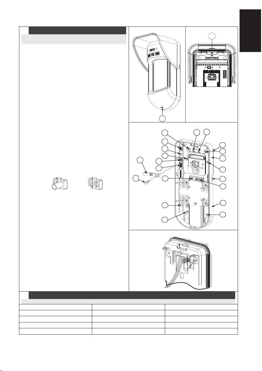
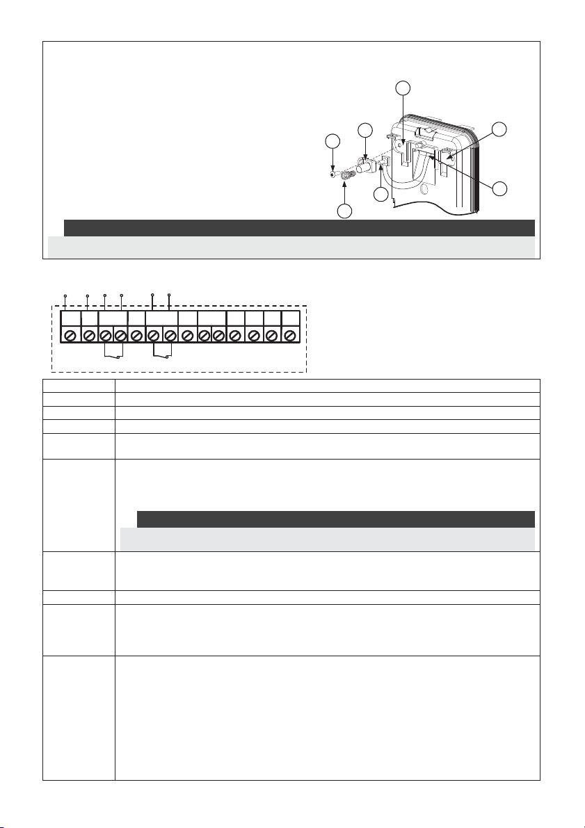
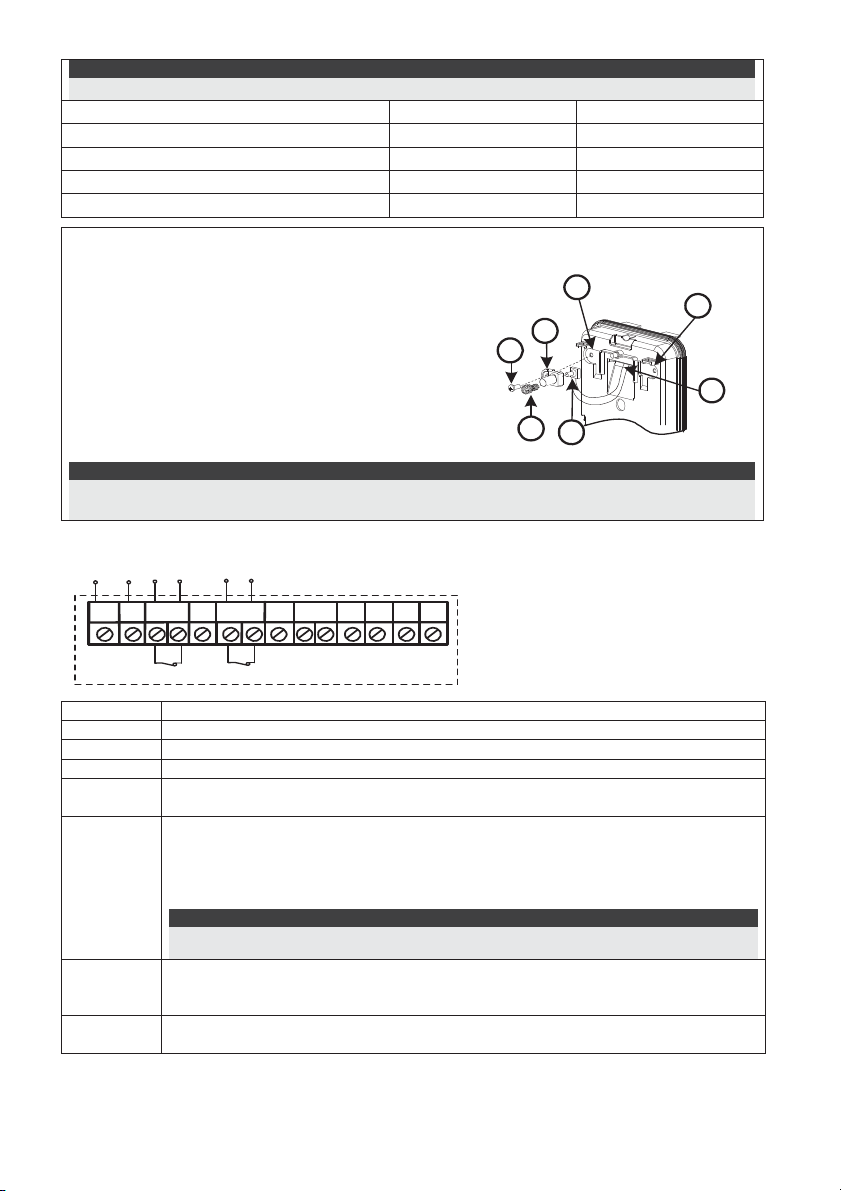
Terminal Wiring
12VDC
Right Side
Tamper
7
5
+-
+,ALARM
FREE YEL
TAMPER
FREE
ALARM
N.C
FREE
YEL
TAMPER
N.C
FREE
GREEN
LEDs
AM
ENABL
WatchOUT DT - PCB
12 VDC
N.C relay, 24VDC , 0.1A
This terminal is a free pin that can be used to connect wires and EOL resistors
N.C switch, 24VDC , 0.1A
This terminal is a free pin that can be used to connect wires and EOL resistors
DUST TEST
SET/
UNSET
GREEN
AM
Normally closed AM relay output (
24VDC, 0.1A) indicates Anti Masking alarm or any
trouble in the detector (not including dust/dirty lens).
The Proximity AM enables receiving sabotage alerts before the detector is
damaged or masked, using both microwave channels.
Note:
When DIP8 is defined as Enabled this relay also opens momentarily when a Proximity AM
LED
ENABLE
attempt occurs.
Used to remotely control the LEDs when DIP1 is set to ON.
Enable: input is +12V OR no terminal connection
Disable: Connect the input to 0V
DUST N.O. collector max 70 mA. Indicates that the lens is dirty and requires cleaning.
TEST
Used to perform remote alarm testing to the detector by applying 0 volts to this
terminal.
Success: Alarm relay is momentary opened.
Failure: AM relay is opened
SET/
UNSET
This input enables to control Anti-masking and LEDs operation in accordance to
the system status, Set (Arm) / Unset (Disarm).
While the system is armed this feature prevents an intruder from gaining
knowledge of the detector’s status and disables Anti-masking detection.
System Status Input Status AM Relay LEDs
Set (Arm) 0V Of
Unset (Disarm) 12V or no connection On* On**
* DIP7 is ON (Anti masking enabled)
** DIP1 is ON (LEDs enabled) and LEDs ENABLE input terminal is enabled
(+12V OR no terminal connection).
6 WatchOUT 315DT Installation Manual
Page 7
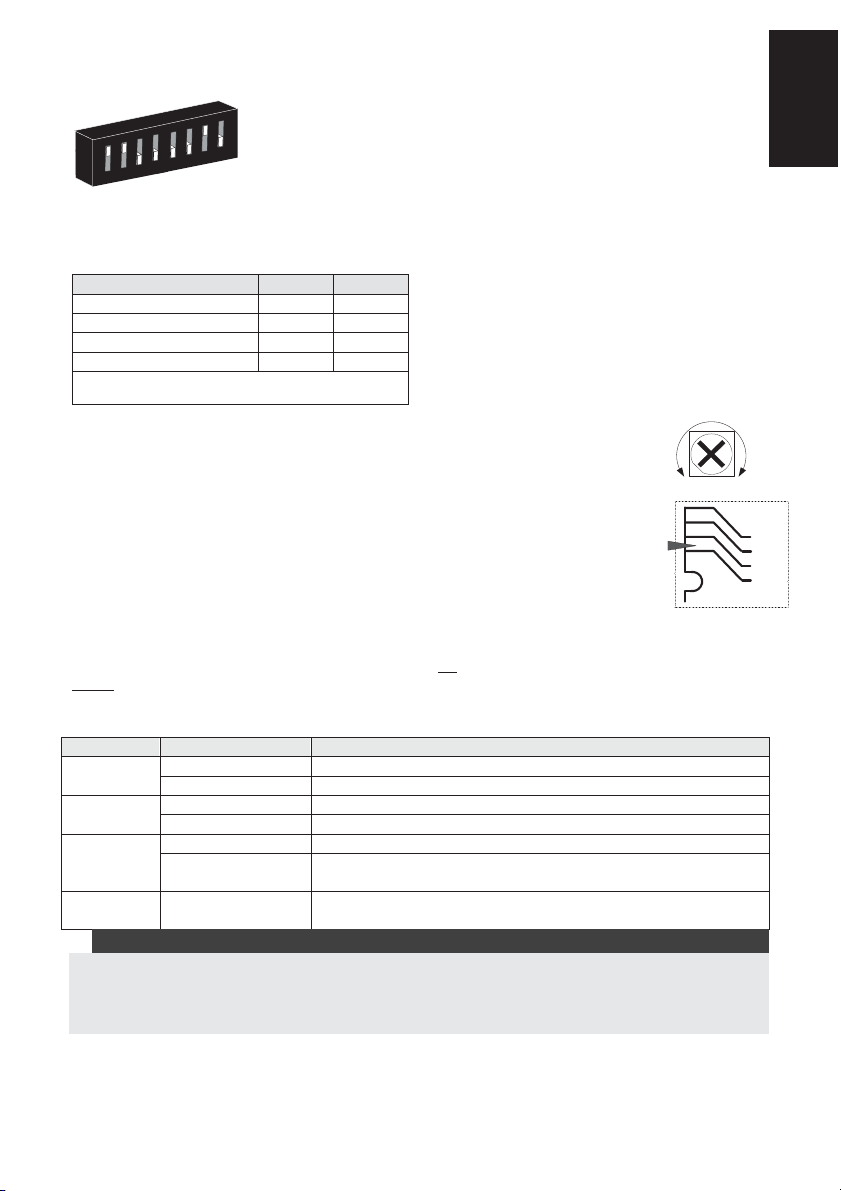
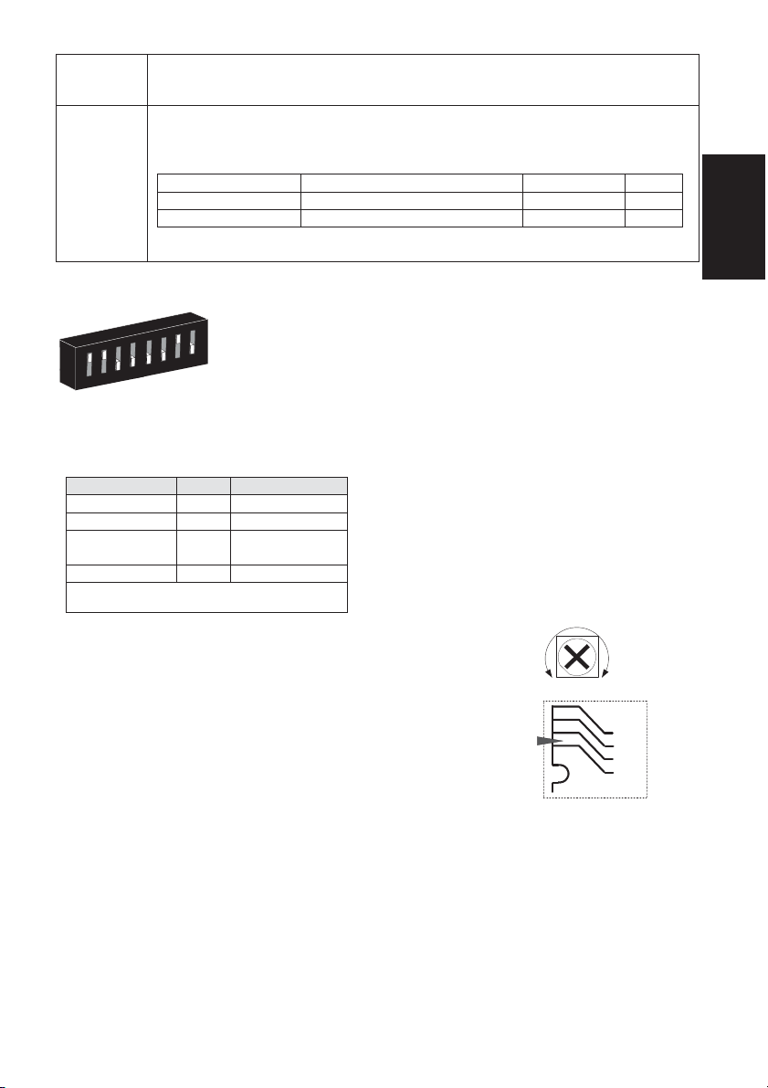
DIP Switch Settings
O
N
O
3
2
1
7
6
5
4
8
Factory Defaults
DIP 1: LEDs operation
On: LEDs Enabled
Off: LEDs Disabled
DIP 2-3: Detection Sensitivity
Sensitivity DIP2 DIP3
Low Off Off
Mid Off On
Normal (Default)
On Off
Maximum* On On
* In maximum sensitivity sway recognition is
disabled to achieve maximum sensitivity
DIP 4: Anti masking Sensitivity
On: High
Off: Low
DIP 5: Detector's optics
On: Barrier / Long range
Off: Wide angle
DIP 6: Red LED /3 LED
On: Red LED only
Off: 3 LEDs
DIP 7: Anti masking operation
On: Enabled
Off: Disabled
DIP 8: Proximity AM
On: Enabled
Off: Disabled
Microwave Adjustment
Adjust Microwave coverage area by using the trimmer on the PCB.
Walk test
Two minutes after applying power, walk test the protected area to verify
proper operation.
For installations on uneven surfaces slide the PCB inside the internal base to
the appropriate setting according to the desired height (1.0m, 1.5m, 2.2m,
2.7m) as printed on the bottom left corner of the PCB or use the standard
swivel accessory.
For reducing the detection range, slide the PCB up
.
down
or tilt the swivel
MIN
MAX
PCB
1.00M
1.50M
2.20M
2.70M
English
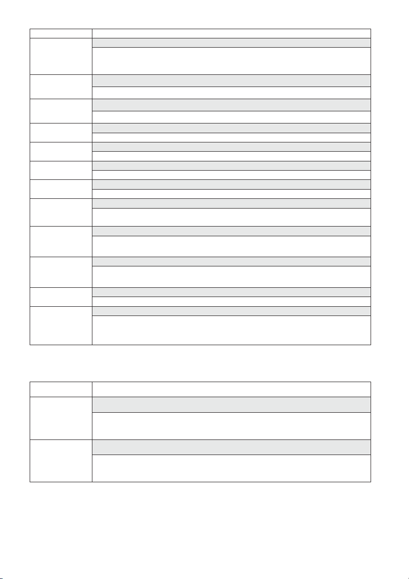
LEDs Display
LED State Description
YELLOW
GREEN
RED
All LEDs
Notes:
1. DIP-Switch 1 should be in ON position to enable LED indications.
2. Only one LED is active at any one time. For example, in the case of both PIR and MW detection, either the
steady YELLOW LED or the steady GREEN LED is displayed (the first to detect), followed by the Alarm RED
3. In order to prevent the analysis of detection technologies such as PIR, Microwave, Active IR AM and
Proximity AM, set DIP Switch 6 (SW1) to ON. Only the red LED will be activated.
WatchOUT 315DT Installation Manual 7
Steady Indicates PIR detection
Flashing Indicates Active IR AM (Anti mask) detection
Steady Indicates MW detection
Flashing Indicates Proximity AM detection
Steady Indicates ALARM
Flashing Indicates malfunctioned communication with ProSYS (BUS
mode only)
Flashing (One
Unit initialization on power up
after another)
Page 8
Relay Mode / BUS Mode Jumper
J-BUS jumper (located on the PCB between the red and green
LEDs) is used to define the detector’s mode of operation as
follows:
Relay
Mode
O
N
BUS Mode
N
O
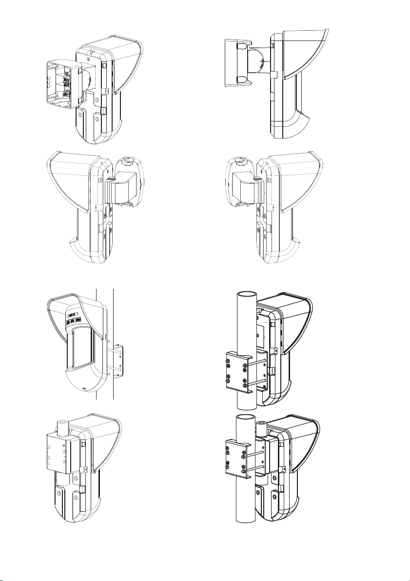
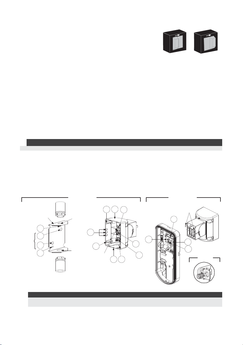
Standard Swivel Installation
The Outdoor detector packaging contains a standard swivel for flexible installation. Please follow
the instructions below for mounting the detector with the Standard Swivel:
1. Open WatchOUT front cover (Unlock C1, Figure1).
2. Release internal base (Unlock I1, Figure 2).
3. Open knockouts on external base (Figure 6, Detail B)
• W1: Wires knockout
• S1,S2: Knockouts for securing external base to Standard Swivel
• S3: External base locking screw knockout
4. On the swivel accessory remove the required swivel cable wiring knockout S2, S7 or S9
(Figure 6, Detail A).
5. Remove back tamper from the internal base (see “Changing Back Tamper Position"
paragraph) and connect it to S5 (Figure 6, Detail A) on the Standard Swivel.
Note:
Ensure that you see the engraved UP mark on the upper front face of the swivel.
6. Select the mounting installation type as follows:
Wall Mounting
a. Insert external cable wiring through knockouts S2, S7 or S9 and extract them (including the
tamper wires) through the Swivel Wires Passage (Figure 6, Detail B).
b. Secure swivel to the wall through holes S1, S3, S6 and S8.
Swivel Conduit Mounting (using Conduit Metal Swivel Adaptor – CSMA, Figure 6, Detail A)
Tamper
Spring
Holes
M1
M2
M3
M4
CSMA
Detail A Detail B
Ø 16 mm
Ø 21 mm
Standard Swivel
S1
S9
S8
Swivel Wires
Passage
S2
S7 S6
S3
S4
Tamper
(see Detail C)
Snaps
W1
S1
S5
S2
S3
Detail C
Figure 6
Note:
The CSMA is required when wall external wiring is used and protection pipe is required. The CSMA should
be ordered separately - P/N RA300SC0000A.
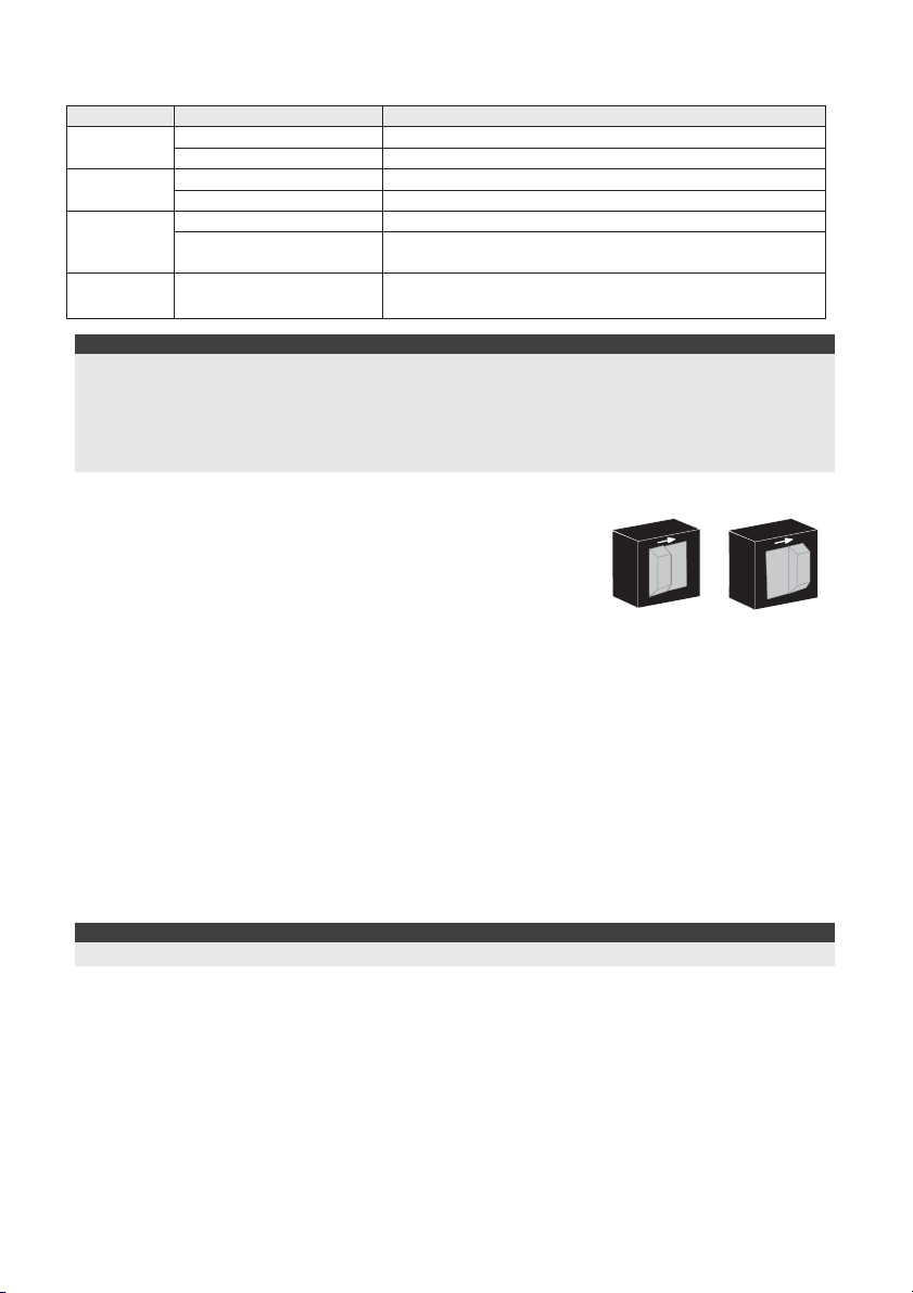
a. Choose the direction upon which to mount the CSMA according to the required diameter:
16mm (0.63 inches) or 21mm (0.83 inches).
b. Insert conduit to the CSMA.
8 WatchOUT 315DT Installation Manual
Page 9
c. Secure CSMA to the wall through points (M1, M4).
d. Insert external cables and tamper wires from the conduit through the swivel wires
passage of the swivel (Figure 6, Detail A).
e. Secure swivel to the wall through holes S1, S3, S6 and S8.
Note:
The Tamper spring S5 (Figure 7) should make contact with the wall through the tamper spring holes M2 or
M3 on the CSMA. Make sure to hear the tamper "Click" when connecting to the wall.
7. Insert tamper wires and external cable wiring from Standard Swivel through knockout W1 on
the external base (Figure 6, Detail B).
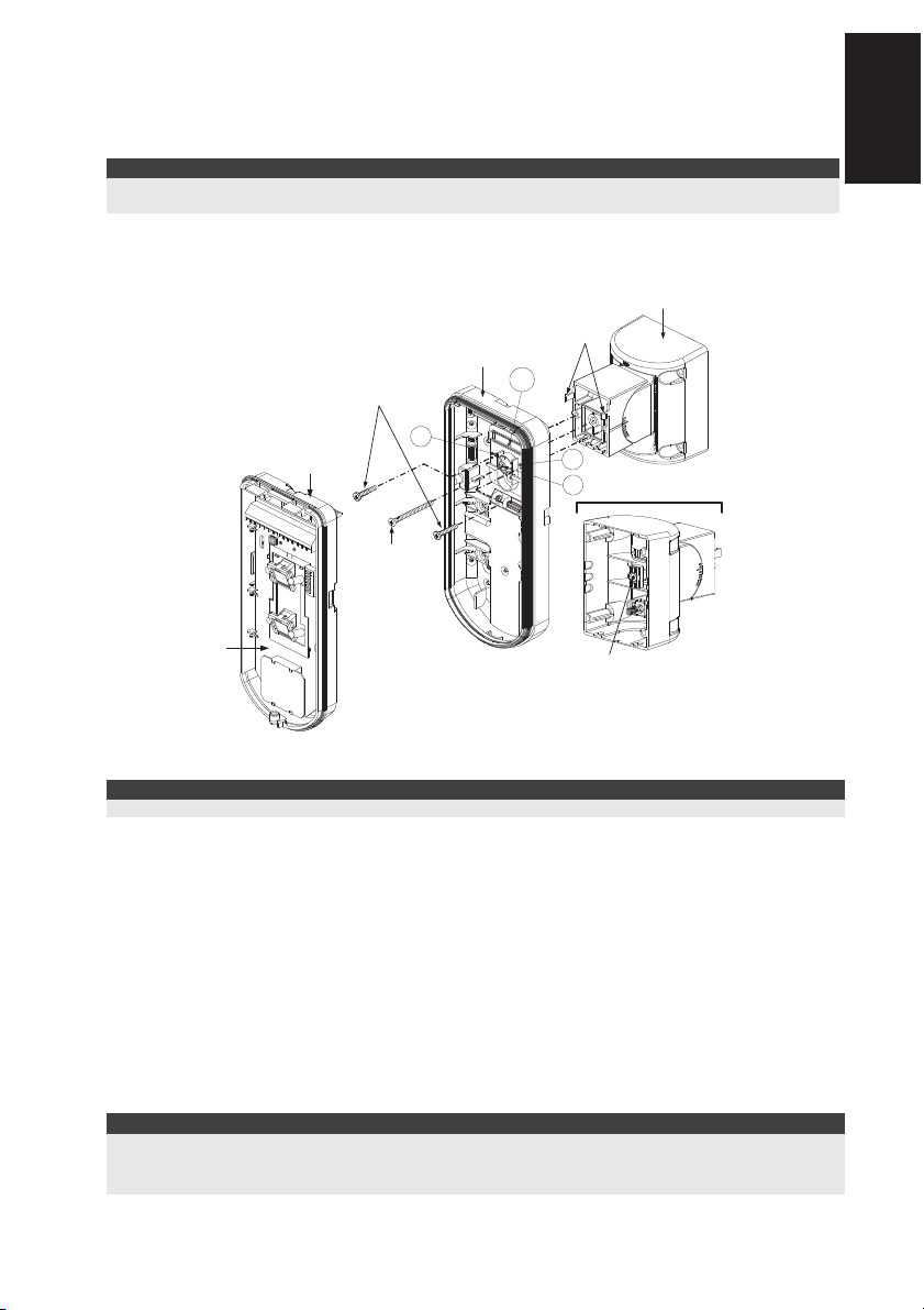
8. Connect the external base to the swivel using the dedicated snaps (Figure 7).
Swivel to External Base
Connecting Screws
Internal Base
S1
Angle Locking
Screw
(See Note 2)
External Base
See Detail A
Snaps
W1
S2
S3
Detail A
English
PCB
Swivel Assy
Connectin g Screw
(See Note)
Figure 7
Note:
Do not open or close the Swivel Assy Screw since it is used for connecting the swivel parts only.
9. Secure external base to swivel with two screws fastened to knockouts S1 and S2 (Figure 7).
10. Insert the supplied angle locking screw from the external base through the angle locking screw
knockout S3 on the external base to the standard swivel (Figure 7).
11. Tilt and Rotate the Standard Swivel to the desired position. Once the Standard Swivel is in the
desired position, secure the angle locking screw.
12. Line up the internal base onto the external base. Insert all wiring cables through the internal
base.
13. Secure internal base to external base (Lock I1, Figure 2).
14. To readjust the Standard Swivel when the PCB is installed (Figure 7):
a. Bend down the black foam located below the RED LED on the PCB (enough to reach the
Swivel locking screw).
b. Use a Philips screwdriver to release the locking screw (see Figure 8).
c. Tilt and/or Rotate the Standard Swivel to the desired position.
d. Secure the angle locking screw.
Note:
When marks on the two movable parts are aligned (Figure 8), the Standard Swivel is in 0°
vertical /horizontal position. Each click from this position represents shifting of 5° in vertical / horizontal
position.
15. Close the front cover (Lock C1, Figure 1) and walk test the detector.
WatchOUT 315DT Installation Manual 9
Page 10
Note:
The screw has to pass through External Base and locked to the swivel.
Figure 8
Replacing Lenses
1. Unlock the six screws that hold the lens holding sleeve from the back of the front cover.
2. To release the protective sleeve, gently push the lens from the external side of the front cover.
3. Disconnect the lens from the sleeve by gently pushing the lens clips that secure it to the
sleeve.
4. Replace the lens. Place the 4 clips of the lens into the matching holes on the sleeve.
5. Insert the protective sleeve back into place on the front cover. Pay attention to place the
sleeve over the sealing rubber.
6. Secure the 6 holding screws back to their place.
Sleeve Locking
Screws
Lens Locking
Clips
Lens Prot ecting
Sleeve
Sockets for
Lens Clips
10 WatchOUT 315DT Installation Manual
Sealing Rubber
Front Cover
Locking Screw
Page 11
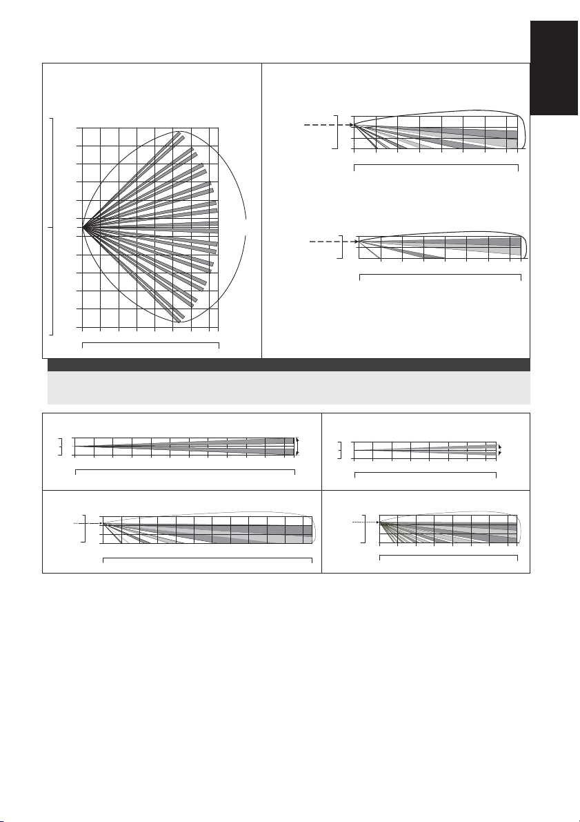
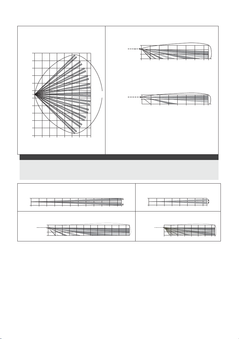
Lens Types
Wide angle lens (RL300) /
Low installation - Pet lens (RL300F) :
40
11
9
30
7
20
5
3
10
1
0
0
1
10
3
5
20
7
30
9
11
40
Feet
0
Top view
2468100121415
20
10
30 40 50
90°
Typical
Installation
Height:
2.2m (7'2")
Typical
Install ation
Height:
1.5m (5'3")
Note:
The detector's Pet Immunity (height of an animal, no weight limitation), is up to 70 cm (2'4"), when installing the
detector at 2.2m (7'2"). If the installation is bellow the height mentioned above, the Pet Immunity decreases
accordingly; every 10 cm (4") decrease in installation height leads to 10 cm (4") decrease in pet imunity.
Long range lens (RL300LR): Top view
Feet
1
3
0
0
3
1
Meters
Typical
Installation
Height:
2.2m (7'2")
246810012141618202223
Feet
0
Long range lens (RL300LR): Side view
Feet
10
0
Meters
Feet
20
10
3
1
0
0
30 40 50
2468100 12141618 20 2223
20
10
30 40 50
60 70 75
60 70 75
Wide angle lens (RL300):
Side View
Feet
10
3
1
0
0
Meters
2468100121415
Feet
0
20
10
30 40 50
Low installation - Pet lens (RL300F) :
Side view
Feet
6
2
1
0
0
Meters
2468100121415
Feet
0
20
10
30 40 50
Barrier lens (RL300B): Top view
Feet
3
5°
1
0
0
3
1
Meters
2468100121415
Feet
0
Barrier lens (RL300B): Side view
Feet
Typical
10
Installation
Height:
2.2m (7'2")
0
Meters
Feet
20
10
3
1
0
0
30 40 50
2468100121415
20
10
30 40 50
English
5°
WatchOUT 315DT Installation Manual 11
Page 12
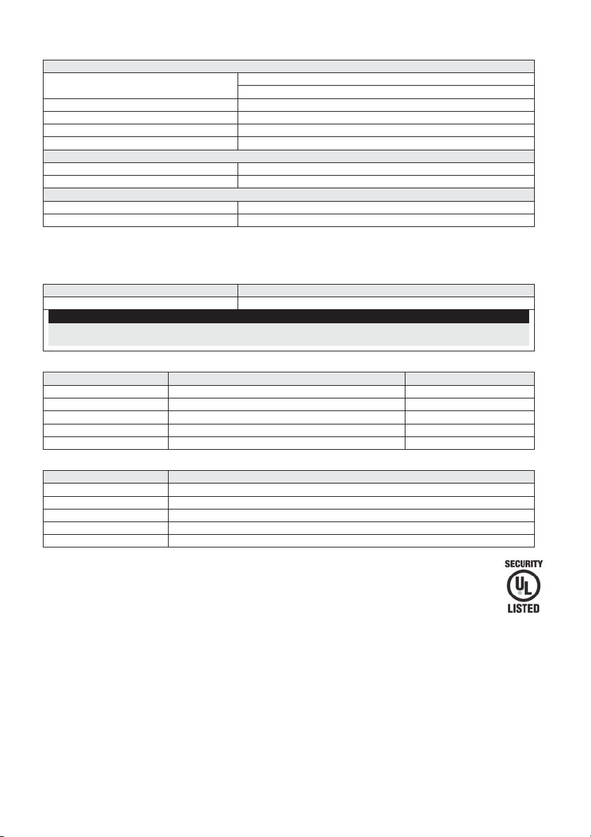
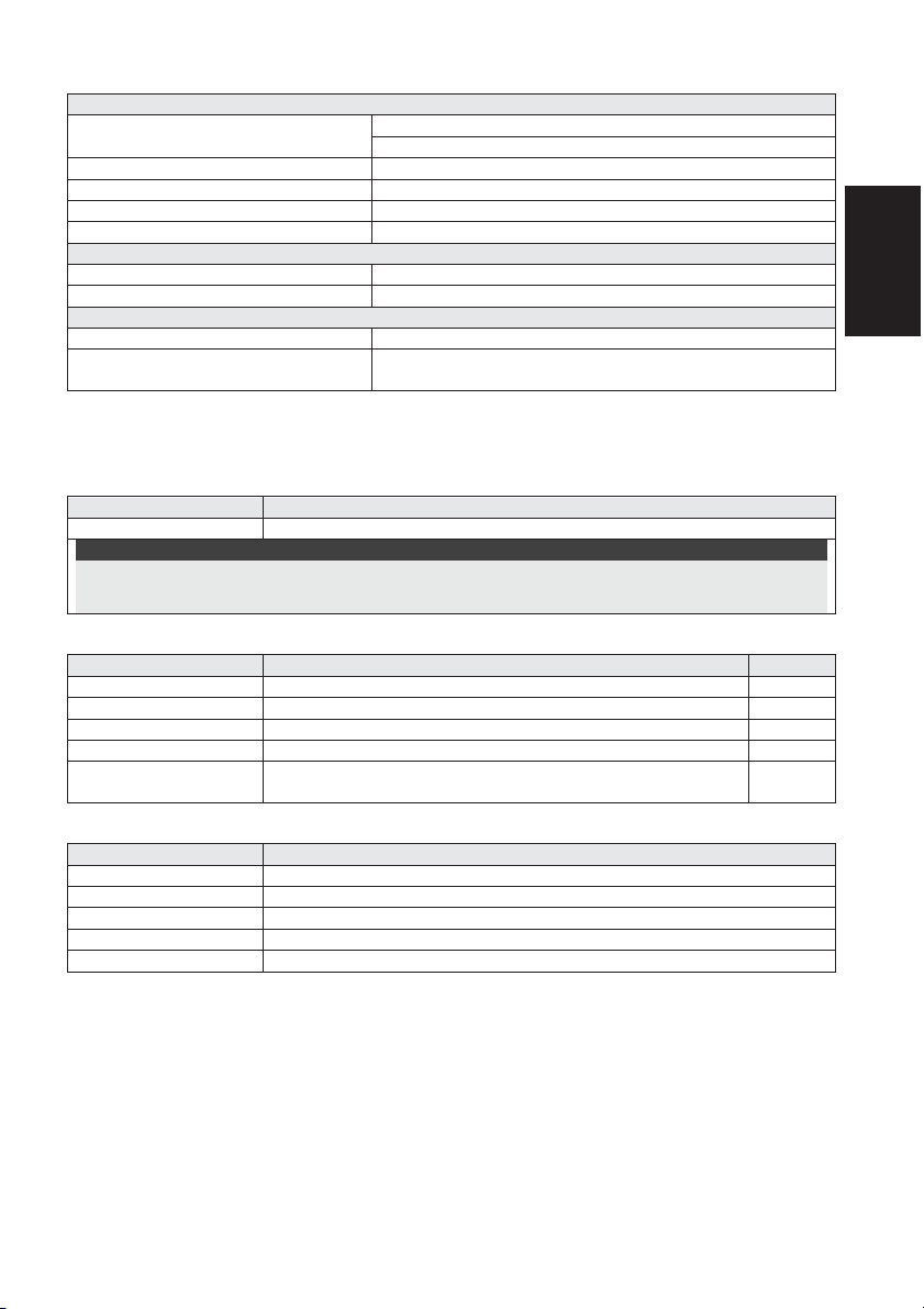
Technical Specification
Electrical
Current consumption 30mA at 12 VDC (Stand by)
42mA at 12 VDC (MAX with LED ON)
Voltage requirements 9 -16 VDC
Alarm contacts 24 VDC, 0.1A
AM contacts 24 VDC, 0.1A
Dust output Open collector 70mA max
Physical
Size: LxWxD 230 x 123 x 124mm (9 x 4.8 x 4.88 in.)
Weight 0.632 Kg (1.4lb)
Environmental
RF immunity According to EN50130-4
Operating/Storage temperature -30°C to 60°C (-22°F to 140°F)
* PIR technology is limited in rough environmental conditions.
Ordering Information
Standard Units
Model Description
WatchOUT 315DT WatchOUT DT + Swivel
Note:
Each of the detectors contains a standard swivel and 3 replacement lenses (P/N engraved on the Lens) 1.7m
low installation pet (RL300F), long-range (RL300R) and barrier lens (RL300B).
Accessories Kits
Model Description Weight
RA300B WatchOUT Barrier Swivel Kit 0.1 Kg (0.23 lb)
RA300P WatchOUT Pole Adaptor Kit 0.25 Kg (0.55 lb)
RA300C WatchOUT Conduit Adaptor Kit 0.6 Kg (1.27 lb)
RA300HS WatchOUT Demo Housing - RA300SC WatchOUT Swivel Metal Conduit Adaptor 1Kg (2.2 lb)
Camera Option
Model Description
WatchOUT VC1 WatchOUT Camera Cover Adaptor
WatchOUT VC017 WatchOUT Narrow Camera
WatchOUT VC053 WatchOUT Wide Camera
WatchOUT VCPS WatchOUT Camera 220V Power Supply
WatchOUT VCPS WatchOUT Camera 120V Power Supply
UL Compliance Section
To comply with UL, note the following:
♦ The unit is intended for outdoor installation where unwanted alarms are tolerable. If not, it
is recommended to connect it to the trouble circuit of a listed compatible control unit.
♦ A dead zone of 5 ft should be considered during installation.
♦ The camera option is not UL listed.
♦ Disclaimer: PET feature has not been tested or verified by UL.
♦ 0.6 power factor inductive load can be used on the relays.
♦ Relay mode is intended to be connected to listed compatible control unit or power supply that provides 4
hours of standby power.
♦ It may be necessary to set detector at maximum sensitivity to achieve maximum distance.
♦ Do not connect the DUST output to a UL listed product.
♦ When the detectors are connected to the BUS of the ProSYS panel, the detectors are to be powered
from either the ProSYS (Version 7.55) panel or a listed compatible burglar alarm power supply that has
an output voltage range that does not exceed 9-16 vdc, has a minimum of 4 hrs. of standby power, and
is suitable for mercantile use.
12 WatchOUT 315DT Installation Manual
Only P/N:
RK315DT00USB
is UL approved
Page 13
BUS Mode Installation
t
Introduction
The information in this section relates to WatchOUT 315DT installation in BUS Mode only. Up to
32 BUS detectors can be installed on the ProSYS RS485 BUS, saving cabling time and enabling
remote control and diagnostics.
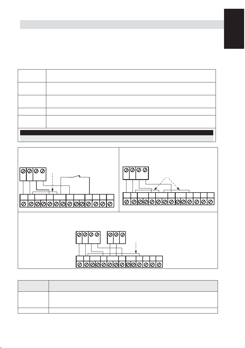
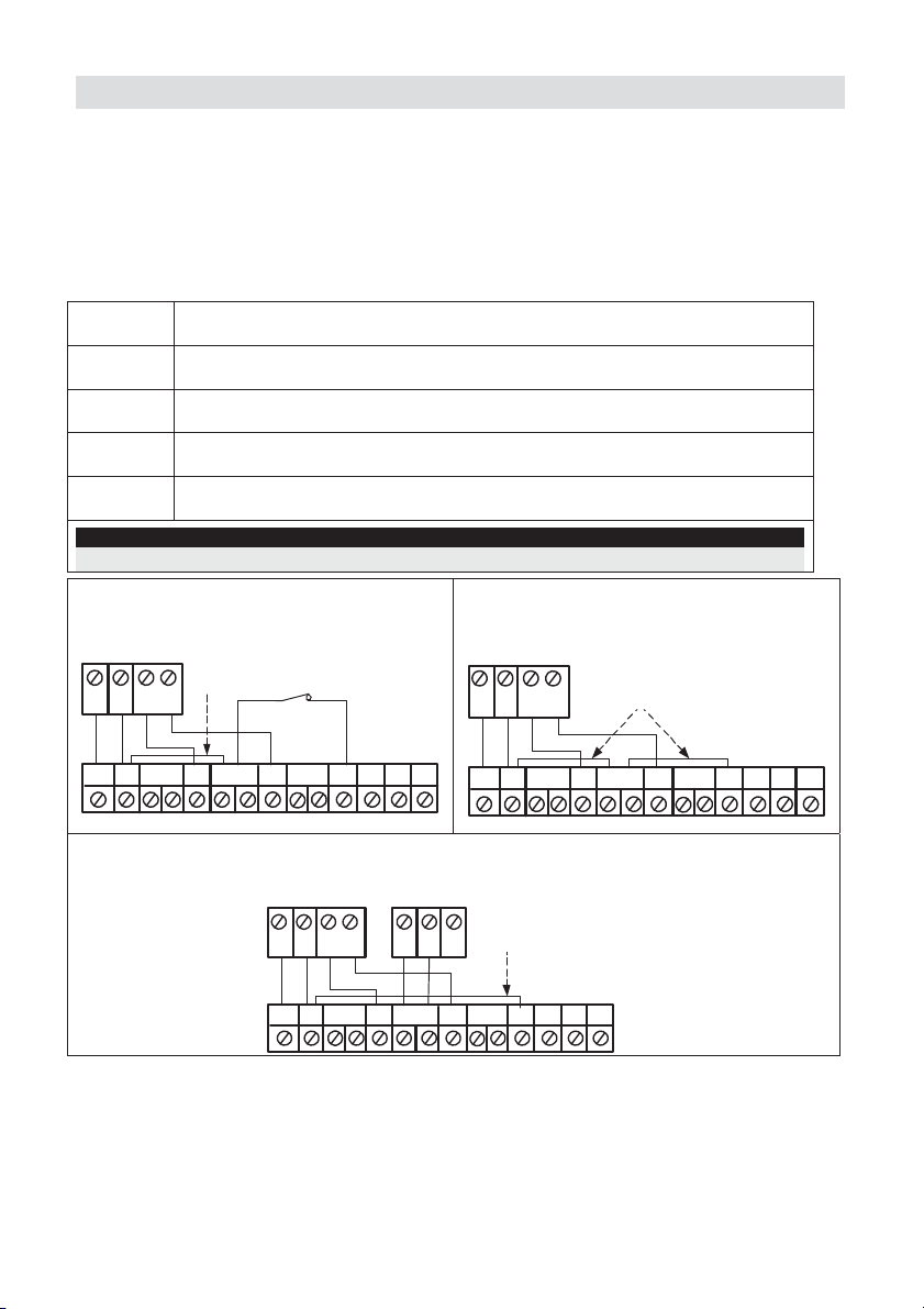
Terminal Wiring
+,-
YELLOW
GREEN Used for data communication with the ProSYS. Connect to the terminal to the
TAMPER
LED
ENABLE
Note:
All terminals that are not mentioned in the table above are unused.
ProSYS
COM
AUX
BLK
RED
+-
Used for the connection of 12VDC power supply. Connect the (+) terminal to
the AUX RED and the (–) terminal to the COM BLK of the ProSYS terminals
Used for data communication with the ProSYS. Connect to the terminal to the
BUS YEL of the ProSYS
BUS GRN of the ProSYS
Used for the wiring for tamper detection, see below
Used for the wiring for tamper detection, see below
Cover and Back Tamper
BUS Mode:
Cover + Back tamper wiring
GREEN
FREE
BACK
TAMPER (N.C)
Short
BUS
YEL
GRN
TAMPER
FREE
ALARM
YEL
AUX
RED
LEDs
AM
DUST TEST
ENABLE
UNSET
+-
SET/
Cover Tamper Only
ProSYS
COM
BUS
BLK
YEL
GRN
FREE
ALARM
YEL
BUS Mode:
Cover Tamper Wiring
Short
FREE
TAMPER
GREEN
Cover Tamper to Zone Inpu
AUX
RED
ProSYS
BUS
COM
BLK
Zone
Input
BUS
YEL
Zone
COM
Z1 Z2
GRN
BUS Mode:
Cover Tamper to Zone Input
Short
LEDs
AM
ENABLE
DUST TEST
UNSET
SET/
English
+-
ALARM
FREE
GREEN
YEL
FREE
TAMPER
LEDs
AM
ENABLE
DUST TEST
UNSET
SET/
DIP Switch Settings
DIP Switch
Number
1 - 5 Used to set the detector ID number. Set the ID number in the same way as for
6 - 8 Not used
WatchOUT 315DT Installation Manual 13
Description
any other ProSYS accessory (Refer to the ProSYS installation instruction
manual)
Page 14
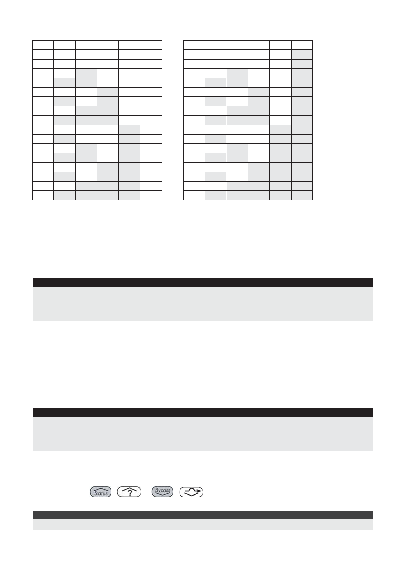
WatchOUT ID: DIP Switches 1 - 5
ID 1 2 3 4 5 ID 1 2 3 4 5
01 OFF OFF OFF OFF OFF 17 OFF OFF OFF OFF ON
02 ON OFF OFF OFF OFF 18 ON OFF OFF OFF ON
03 OFF ON OFF OFF OFF 19 OFF ON OFF OFF ON
04 ON ON OFF OFF OFF 20 ON ON OFF OFF ON
05 OFF OFF ON OFF OFF 21 OFF OFF ON OFF ON
06 ON OFF ON OFF OFF 22 ON OFF ON OFF ON
07 OFF ON ON OFF OFF 23 OFF ON ON OFF ON
08 ON ON ON OFF OFF 24 ON ON ON OFF ON
09 OFF OFF OFF ON OFF 25 OFF OFF OFF ON ON
10 ON OFF OFF ON OFF 26 ON OFF OFF ON ON
11 OFF ON OFF ON OFF 27 OFF ON OFF ON ON
12 ON ON OFF ON OFF 28 ON ON OFF ON ON
13 OFF OFF ON ON OFF 29 OFF OFF ON ON ON
14 ON OFF ON ON OFF 30 ON OFF ON ON ON
15 OFF ON ON ON OFF 31 OFF ON ON ON ON
16 ON ON ON ON OFF 32 ON ON ON ON ON
ProSYS Programming
The following section describes the additional software programming options, added to the
ProSYS software, that concern the settings of the WatcOUT DT as a BUS detector. Up to 32 BUS
detectors can be added to the system (16 in ProSYS 16) and each of them comes at the expense
of a zone in the system.
It is recommend reading and fully understanding the ProSYS Installation and User Manuals,
before programming the WatchOUT.
Notes:
The WatchOUT is compatible with the ProSYS software Version 4.xx and above.
The WatchOUT can be programmed via the U/D Software from UD Version 1.8 and above.
For maximum operation stability, it is best NOT to exceed a total of 300 meters (1000 feet) of wiring when
connecting the WatchOUT to the BUS.
Adding / Deleting the WatchOUT DT
The WatchOUT is part of a new accessory category, BUS zones. Therefore, Adding/Deleting the
WatchOUT is identical to any other accessory with the following exception:
Each BUS Zone Detector should be assigned to a Regular Zone.
Any BUS detector can be assigned to a physical wired zone or to a virtual zone.
Physical zone: Any zone on the ProSYS PCB (zones 1-8) or on a wired zone expander
(ZE08, ZE16).
Virtual zone: Any zone on a BUS zone expander defined as BZ08 or BZ16.
Notes:
Virtual BUS zones are cost effective. They enable to expand your system zones without adding physical zone
expanders.
The virtual BUS zone expander can be used only for BUS zone detectors.
To add a BUS zone expander select type BZ08 or BZ16 when adding a zone expander (Quick key [7][1][2]).
1. To Add / Delete the WatchOUT DT
1. From the installer menu enter the Add/Delete menu: Quick Key [7][1][9][5] for BUS Zones
detectors.
2. Use the
ID number for which you want to assign (or delete) a detector.
Note:
Make sure that the detector's physical ID number is identical to the ID number you select during programming.
/ or / keys to position the cursor over the BUS Zone
14 WatchOUT 315DT Installation Manual
Page 15

3. Place the cursor on the TYPE field and use the / key to select ODT15 for the
t
WatchOUT DT detector.
4. Press
/ to confirm.
5. Repeat the process for the other BUS detectors.
2. Assigning the WatchOUT DT to a Zone
1. From the main installer menu enter Zones: One by One option (Quick key [2][1])
2. Select the zone number that you want to assign the BUS detector.
Note:
If you defined a BUS Zone Expander, select a zone number from the virtual zones (defined by the BUS zone
expander).
3. Define Partitions, Groups, Zone Type and Zone Sound.
4. In the Termination category select [5] BUS Zone followed by
/ .
The following display appears:
Z:001 LINK TO:
Z:001 LINK TO:
ID:01 TYPE=ODT15
ID:01 TYPE=ODT15
5. Select the BUS zone number to assign to the programmed zone. The type field will be
updated automatically when selecting the zone.
6. Press
/ . The loop response category is not applicable to a BUS zone and the
following display appears:
Z:001 RESPONSE:
Z:001 RESPONSE:
N/A-BUS ZONE
N/A-BUS ZONE
7. Press
/ , assign label and press / .
3. Configuring the WatchOUT DT Parameters
1. To access the WatchOUT settings option press [2][0][3] from the main installer menu. The
following display appears:
B-ZONE PRMS:
B-ZONE PRMS:
ZONE#=001 (M:ZZ)
ZONE#=001 (M:ZZ)
2. Select the zone that the BUS zone was assigned to and press
/ . You can
now program the WatchOUT parameters as follows:
Zones Miscellaneous: BUS Zone
Quick Keys Parameter Defaul
[2][0][3][zzz]
[1]
[2][0][3][zzz]
[1][1]
[2][0][3][zzz]
[1][2]
LEDS 3 LEDS
Defines the LEDS operation mode.
Off
Disables the LEDS operation.
Red Only
Only the Red led will operate. This option is highly recommended to avoid the
possibility that the intruder will “Learn” the detector behavior.
[2][0][3][zzz]
[1][3]
[2][0][3][zzz]
[2]
[2][0][3][zzz]
[2][1]..[4]
[2][0][3][zzz]
[3]
3 LEDS
All 3 LEDs will operate.
PIR Sensitivity Normal
Defines the sensitivity of the detector(MW + PIR)
Sensitivity Options
1) Low
2) Medium
3) Normal
4) High
MW Range Trimmer
Defines the microwave channel range. The maximum is 23m.
English
WatchOUT 315DT Installation Manual 15
Page 16
Quick Keys Parameter Defaul
t
[2][0][3][zzz]
[3][1]..[7]
[2][0][3][zzz]
[4]
[2][0][3][zzz]
[4][1]..[2]
[2][0][3][zzz]
[5]
[2][0][3][zzz]
[5][1]..[2]
[2][0][3][zzz]
[6]
[2][0][3][zzz]
[6][1]..[2]
[2][0][3][zzz]
[7]
[2][0][3][zzz]
[7][1]
[2][0][3][zzz]
[7][2]
[2][0][3][zzz]
[8]
[2][0][3][zzz]
[8][1]..[2]
MW Range options
1) Minimum
2) 20%
Anti-Mask sensitivity Low sensitivity
Defines the sensitivity of the active IR AM
Anti-Mask sensitivity option
1) Low Sensitivity 2) High Sensitivity
Lens Type Wide Angle
Defines the actual Lens of the detector
Lens Type Options
1) Wide Angle 2) Barrier / Long Range
Anti-Mask Enable
Defines the operation of Anti Masking detection
Anti-Mask Options
1) Disable 2) Enable (Default)
Arm/Disarm No
Defines the operation of the LEDs anti masking detections while the detector
is armed
No
Active IR AM and Proximity AM (Anti masking) is enabled
LEDs behave according to the LEDs parameter definition
Yes
Active IR AM and Proximity AM (Anti masking) is disabled
LEDs are disabled
Proximity AM Disable
Defines the operation of the Proximity Anti Masking detection
Proximity AM Options
1) Disable (Default) 2) Enable
NOTE: Disable Proximity AM during heavy rain (if WatchOUT 315DT is not
sheltered) to prevent Proximity AM alerts.
3) 40%
4) 60%
5) 80%
6) Maximum
7) Trimmer (MW is defined
by the trimmer setting on
the PCB)
System Parameters
System: System Control
Quick Keys Parameter Default:
[1][2][36] IR AM=Tamper No
Used to determine the operation of Active IR Anti Masking detection
Yes: Active IR Anti mask detection will activate tamper alarm.
No: Active IR Anti mask detection will be regarded as trouble event.
[1][2][37] Prox AM=Tamper No
Used to determine the operation of the Proximity Anti Masking detection
Yes: Proximity Anti mask detection will activate tamper alarm.
No: Proximity Anti mask detection will be regarded as a trouble event.
16 WatchOUT 315DT Installation Manual
Page 17
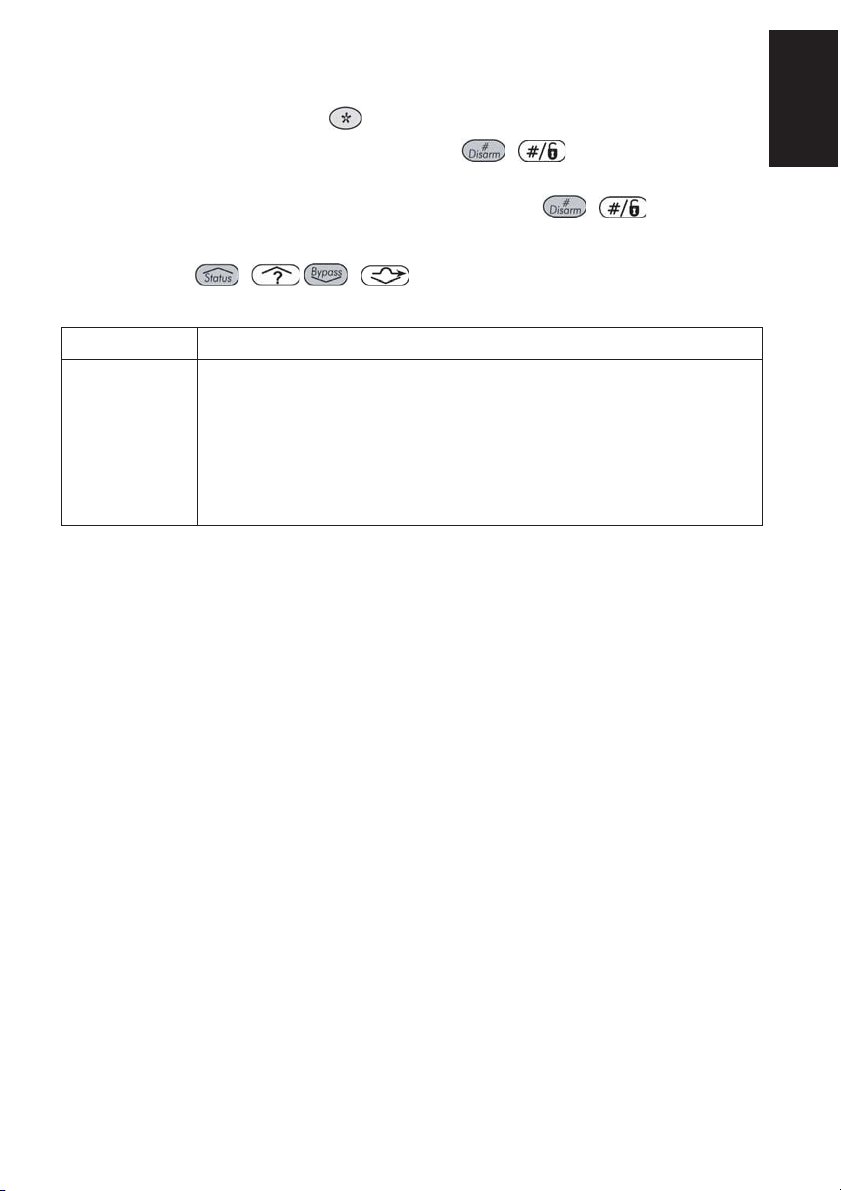
Diagnostics
The ProSYS enables you to test parameters that reflect the operation of the detector.
1. From the main user menu press
2. Enter the Installer code (or sub-installer) and press
[4] to access the Maintenance menu.
/ .
3. Press [9] [1] to for the BUS Zones diagnostic menu.
4. Enter the digit of the zone that you want to test and then press
/ . The system will
perform the diagnostics test and a list of test parameters will appear, as indicated in the table
below.
5. Use the keys
/ / to view the diagnostics test results.
User Menu: 4) Maintenance → 9) Diagnostic → 1) BUS Zone
Quick Keys Parameter
[4][9][1][zzz] Detector Input Voltage: Display the input voltage of the detector.
PIR 1 Level: PIR channel 1 DC level. Range 0.1v - 4v
PIR 1 Noise Level: PIR channel 1 AC level. Range 0VAC (No noise) - 4VA
PIR 2 Level: PIR channel 2 DC level. Range 0.1v - 4v
PIR 2 Noise Level: PIR channel 2 AC level. Range 0VAC (No noise) - 4VA
MW 1 Level: MW channel 1 DC level Range 0.1v - 4v
MW 1 Noise Level
: MW channel 1 AC level (0VAC (No noise) - 4VAC)
MW 2 Level: MW channel 2 DC level Range 0.1v - 4v
MW 2 Noise Level: MW channel 2 AC level (0VAC (No noise) - 4VAC
English
WatchOUT 315DT Installation Manual 17
Page 18

18 WatchOUT 315DT Installation Manual
Page 19

Indice Dei Contenuti
Installazione in modalità relé ............................................................................................... 20
Introduzione .......................................................................................................................... 20
Installazione ........................................................................................................................... 20
Considerazioni per l’installazione ....................................................................................... 20
Installazione a parete ......................................................................................................... 21
Installazione piana ............................................................................................................. 21
Installazione angolare di 45° (installazione a sinistra) ......................................................... 21
Modifica della posizione del tamper antirimozione .............................................................. 22
Cablaggio morsettiera ........................................................................................................... 22
Predisposizione Microinterruttori .......................................................................................... 23
Regolazione microonda ......................................................................................................... 23
Prova di movimento ........................................................................................................... 23
Indicatori LED......................................................................................................................... 24
Microinterruttore Modalità Relé / BUS .................................................................................. 24
Installazione dello snodo standard ........................................................................................ 24
Installazione a parete ......................................................................................................... 24
Installazione per tubo elettrico ............................................................................................ 25
Sostituzione delle Lenti .......................................................................................................... 27
Tipologie di Lenti ................................................................................................................ 28
Caratteristiche Tecniche ......................................................................................................... 29
Informazioni per l’ordine ....................................................................................................... 29
Installazione in modalità BUS .............................................................................................. 30
Introduzione .......................................................................................................................... 30
Cablaggio morsettiera ........................................................................................................... 30
Tamper Antiapertura e Antirimozione............................................................................. 30
Solo Tamper Antiapertura .............................................................................................. 30
Tamper Antiapertura ad un Ingresso di Zona ................................................................. 30
Predisposizione microinterruttori .......................................................................................... 31
Programmazione ProSYS ....................................................................................................... 31
Aggiunta e Cancellazione del WatchOUT DT ..................................................................... 31
Configurazione dei parametri del WatchOUT DT ................................................................ 32
Parametri di Sistema .............................................................................................................. 33
Italiano
Manuale di installazione WatchOUT 315DT 19
Page 20
Installazione in modalità relé
Introduzione
Il rivelatore da esterno Doppia Tecnologia WatchOUT 315DT di RISCO Group è un dispositivo a
microprocessore che elabora i segnali rilevati tramite due canali all’infrarosso passivo (PIR) e due
canali a microonda (MW). Il rivelatore può funzionare come rivelatore tradizionale con uscite a
relé collegabili a qualsiasi centrale d’allarme, o come rivelatore indirizzato via BUS 485 collegato
ai sistemi ProSYS di RISCO. Quando viene collegato ai sistemi ProSYS, il rivelatore può essere
programmato e testato sia localmente che in remoto tramite tastiere LCD ProSYS e/o software di
Teleassistenza RISCO. Le istruzioni che seguono descrivono l’installazione e la configurazione
del WatchOUT 315DT sia in modalità Relé che via BUS. Per informazioni sul collegamento in
modalità BUS ProSYS, consultare il capitolo “Installazione in modalità BUS
”.
Installazione
Considerazioni per l’installazione
1m - 2.7m
(3'3" - 8'9")
Altezza di installazione: Grandangolo 15m
90° (RL300)
Se possibile, evitare di direzionare l’unità verso
oggetti in movimento (alberi ondeggianti,
cespugli, ecc.)
Note:
1. Per altezze di installazione basse, al di sotto di
1.7m ove è richiesta l’opzione di
discriminazione animali, vanno utilizzate le lenti
RL300F (muri bassi o installazione su
recinzioni).
2. La discriminazione animali (altezza
dell’animale senza limiti di peso) arriva fino a
70 cm con il rivelatore installato a 2.2m. Se
l’altezza di installazione è al di sotto di 2.2
metri la discriminazione animali si riduce
proporzionalmente. Ogni 10cm in meno
rispetto a 2.2 metri corrispondeono 10 cm in
meno di altezza dell’animale discriminato.
Per quelle installazioni vicino a strade ad intenso traffico di
veicoli o oggetti oltre l’area di rilevazione desiderata, si
5m (16')
Mantenere una distanza
di almeno 5m (16') da
oggetti in movimento
Fuori campo di
rilevazione
Assicurarsi che nessun oggetto ostruisca il
campo di rilevazione dell’unità sia per la
sezione a microonda sia per quella ad
infrarossi. Prestare attenzione alla crescita di
alberi, rami e ad eventuali altre piante che con
il tempo possono coprire l’area di rilevazione.
consiglia di regolare la sensibilità della microonda (MW) e/o
inclinare il rivelatore verso il basso.
Nota:
Inclinando il rivelatore verso il basso è possibile che la funzione di
immunità agli animali si riduca.
Per una migliore rivelazione
selezionare una posizione di
installazione in modo che
l’eventuale intruso attraversi
l’area di copertura del rivelatore
con una traiettoria di circa 45°
rispetto allo stesso.
NOTA: Con la funzione ‘Antiavvicinamento’ abilitata e il sensore installato a cielo aperto, si
raccomanda di creare un riparo sopra di esso per evitare allarmi impropri in presenza di forti
pioggie o alternativamente disabilitare la funzione.
20 Manuale di installazione WatchOUT 315DT
Page 21
Installazione a parete
Nota:
I numeri di riferimento dei fori a sfondare per
l’installazione sono marcati sulla base posteriore.
1. Aprire il coperchio frontale del WatchOUT.
(Svitare C1, figura 1).
2. Sganciare la base interna (svitare I1, fig. 2).
3. Selezionare l’altezza di installazione come
segue:
Installazione piana
Aprire i fori a sfondare della base esterna (fig. 3)
• B1 - B4: Fori a sfondare per installazione
a parete.
• T1: Foro a sfondare per il tamper
antirimozione
• W2 / W3: Fori a sfondare per il
passaggio cavi
Installazione angolare di 45°
(installazione a sinistra)
a. Aprire i fori a sfondare della base esterna
(fig. 3)
• L1, L2 : Fori a sfondare per lato sinistro
• T3: Foro a sfondare per tamper lato
sinistro
• W5 / W6: Fori a sfondare per passaggio
cavi
b. Rimuovere la molla del tamper
c. Sostituire la staffa (Item 1) con l’altra fornita
(Item 2).
Item 1
d. Inserire la leva B del tamper in T5 e T3 e
stringere la vite A (figura 3)
4. Inserire I cavi esterni attraverso la base
esterna W2, W3 (Installazione piana) o W5,
W6 (Installazione a sinistra) (figura 3).
5. Fissare la base esterna alla parete.
6. Inserire i cavi esterni e i cavi del tamper
attraverso la base interna. (figura 4).
7. Fissare la base interna a quella esterna
(bloccare I1, figura 2).
8. Chiudere il coperchio frontale (bloccare C1,
figura 1) dopo aver cablato l’unità e
predisposto i microinterruttori.
9. Effettuare le prove di copertura.
Item 2
Figura 1
Figura 3
Leva del
Tamper
B
A
Figura 4
Figura 2
C1
T1
T3
L1
B1
W5
W6
W3
L2
B4
l1
Italiano
T5
T6
T4
T2
R1
(non visibile )
B2
W9
W2
R2
)
(non visibile
B3
Manuale di installazione WatchOUT 315DT 21
Page 22
Nota:
Per installazioni a 45° lato destro usare le equivalenti predisposizioni sulla base esterna come segue:
Descrizione fori a sfondare Sinistra Destra
Fori a sfondare per il fissaggio della base L1, L2 R1, R2
Foro a sfondare per la molla del tamper T1,T3 T2,T4
Punto di fissaggio vite tamper T5 T6
Fori a sfondare per passaggio cavi W5, W6 W7, W8
Modifica della posizione del tamper antirimozione
Di fabbrica il tamper antirimozione è fissato sul lato
destro della base interna (Vista Posteriore). Se si
desidera spostarlo nella parte sinistra, procedere come
segue (figura 5):
1. Svitare la vite tamper 1 per rimuoverlo dalla posiz. 7.
2. Assicurarsi che la molla 2 del tamper resti posizionata
sulla base 4 del tamper.
3. Assicurarsi che la staffa 3 del tamper resti tra 2 e 4.
4. Fissare la vite 1 del tamper in 3 sulla predisposizione 6.
Figura 5
1
2
Predisposizione
tamper a sinistra
6
3
4
Predisposizione
tamper a destra
7
5
Note:
1. Verificare che si senta un "Click" quando la molla del tamper viene spinta contro il muro.
2. Per l’installazione su palo il tamper può essere spostato nella parte inferiore destra della base interna.
Cablaggio morsettiera
12Vcc
+-
ALARM
FREE
YEL
TAMPER
FREE
GREEN
LEDs
AM
ENABL
DUST TEST
SET/
UNSET
+,ALARM
FREE YEL
TAMPER
FREE
GREEN
AM
N.C
12 Vcc
Relé N.C, 24Vcc, 0.1A
Questo è un morsetto libero per il posizionamento di cavi o resistenze di fine linea.
Relé N.C, 24Vcc, 0.1A
Questo morsetto è un morsetto libero per il posizionamento di cavi o resistenze di
fine linea.
L’uscita a relè N.C. (24Vcc; 0,1A) dell’AM, se attiva indica una condizione di
N.C
SCHEDA ELETTRONICA - WatchOUT DT
Mascheramento o una qualsiasi anomalia del rivelatore (questa uscita NON
segnala l’anomalia “Lenti Sporche”).
L’antiprossimità permette di ricevere un segnale di allarme utilizzando entrambi i
canali microonda, prima che il rilevatore venga manomesso o mascherato.
Nota:
Se il microinterruttore DIP8 è in ON, questo relè si attiva momentaneamente alla rilevazione
dell’avvicinamento.
LED
ENABLE
Ingresso usato per controllare da remoto i LED quando il microint. 1 è in ON.
LED abilitati: Tensione +12V presente o morsetto non connesso
LED disabilitati: 0V presente all’ingresso
DUST Uscita N.O. a collettore aperto, massimo 70 mA. Indica che le Lenti dell’unità sono
sporche ed è necessario pulirle.
22 Manuale di installazione WatchOUT 315DT
Page 23
TEST
fOff
SET/
UNSET
Usato per testare il rivelatore da remoto applicando 0V a questo morsetto.
Test OK: Il relé di allarme si attiva per qualche secondo.
Guasto: L’uscita AM viene attivata.
Questo ingresso permette di abilitare o disabilitare l’antimascheramento e
l’accensione dei LED quando il sistema è inserito (Set) o disinserito (Unset).
A sistema inserito questa funzione disabilita i LED (evitando che un intruso possa
verificare che il sistema ha generato un allarme) e l’antimascheramento.
Stato del sistema Stato ingresso Uscita AM LED
Set (Inserito) 0V Of
Unset (Disins.) 12V o nessuna connessione On* On**
* Microint. 7 ON (Antimascheramento abilitato)
Microint. 1 ON (LED abilitati) e ingresso con tensione +12V o nessuna connessione)
**
Italiano
Predisposizione Microinterruttori
O
N
O
3
2
1
7
6
5
4
8
Impostazioni di
Fabbrica
MIC 1: Predisposizione LED
On: LED abilitati
Off: LED disabilitati
MIC 2-3: Sensibilità di rilevazione
Sensibilità MIC2 MIC3
Bassa Off Off
Media Off On
Normale
On Off
(Default)
Massima * On On
* Con sensibilità massima, la SRT è
disabilitata per avere la massima sensibilità
MIC 4: Sensibilità Anti-Mascheramento
On: Alta
Off: Bassa
MIC 5: Ottica Rivelatore
On: Barriera / Lunga portata
Off: Grandangolo
MIC 6: LED Rosso o 3 LED
On: Solo LED rosso
Off: 3 LED
MIC 7: Antimascheramento
On: Abilitato
Off: Disabilitato
MIC 8: Antiavvicinamento
On: Abilitato
Off: Disabilitato
Regolazione microonda
Regolare la portata della microonda utilizzando il potenziometro
posizionato sulla scheda elettronica del rivelatore.
Prova di movimento
Dopo 2 minuti dall’alimentazione del sensore, effettuare una prova di
movimento all’interno dell’area protetta e verificare il buon
funzionamento e la copertura del rivelatore.
Per regolare la copertura del sensore muovere la scheda elettronica
interna del sensore per la predisposizione appropriata in funzione
dell’altezza di installazione desiderata (1.0m, 1.5m, 2.2m, 2.7m)
come stampato nella parte inferiore sinistra della scheda elettronica o
utilizzare lo snodo standard.
Per ridurre l’area di copertura spostare in alto la scheda elettronica o,
se utilizzato, muovere lo snodo verso il basso.
MIN
MAX
PCB
1.00M
1.50M
2.20M
2.70M
Manuale di installazione WatchOUT 315DT 23
Page 24
Indicatori LED
LED Stato Descrizione
GIALLO
VERDE
ROSSO
TUTTI I
LED
Note:
1. Il microinterruttore 1 deve essere posizionato su ON per abilitare i LED.
2. Solo un LED alla volta può illuminarsi. Per esempio, nel caso di attivazione di entrambe le tecnologie PIR e
MW, o il LED giallo o quello verde si illumina (il primo che rileva), seguito poi dal LED rosso di allarme.
3. Per prevenire che malintenzionati riescano ad analizzare il momento di attivazione delle tecnologie di
rilevazione quali PIR, MW, AM e Antiavvicinamento, impostare il microinterruttore 6 in ON (SW1). In questo
modo si accenderà solo il LED rosso.
Microinterruttore Modalità Relé / BUS
Il microinterruttore J-BUS, situato sulla scheda tra i LED rosso e
verde, viene usato per configurare la modalità di funzionamento
del rivelatore (vedi figura al lato).
Acceso Indica rilevazione PIR
Lampeggiante Indica Antimascheramento sull'IR Attivo (AM)
Acceso Indica rilevazione MW
Lampeggiante Indica Antiavvicinamento della sezione MW (AM)
Acceso Indica ALLARME
Lampeggiante Indica una anomalia di comunicazione con la ProSYS
(solo modalità BUS)
Lampeggiante (uno alla
volta)
Inizializzazione dell’unità all’accensione
Modalità
Relé
N
Modalità
BUS
O
N
O
Installazione dello snodo standard
Il kit fornito con il rivelatore da esterno WatchOUT include uno snodo standard per renderne più
flessibile l’installazione. Leggere le istruzioni seguenti per installare il rivelatore con questo snodo.
1. Aprire il coperchio frontale (Allentare C1, figura 1).
2. Sganciare la base interna (Svitare I1, figura 2).
3. Aprire i fori a sfondare della base esterna (figura 6, Dettaglio B)
• W1: Passaggio cavi
• S1,S2: Fori a sfondare per fissare la base esterna allo snodo standard
• S3: Predisposizioni per le viti di fissaggio della base esterna
4. Sullo snodo aprire le predisposizioni per il passaggio cavi S2, S7 o S9 (figura 6, Dettaglio A).
5. Rimuovere il tamper antirimozione dalla base interna (consultare paragrafo "Modifica della posizione
del tamper antirimozione") e collegarlo a S5 (figura 6, Dettaglio A) sullo snodo standard..
Nota:
Accertarsi che il marchio UP è presente nella parte frontale superiore dell snodo.
6. Selezionare le opzioni di installazione di seguito descritte:
Installazione a parete
a. Inserire il cavo esterno attraverso le predisposizioni S2, S7 o S9 (incluso i cavi del tamper)
ed estrarlo facendolo passare attraverso il passaggio cavi dello snodo
(figura 6, Dettaglio B).
b. Fissare lo snodo alla parete tramite i fori S1, S3, S6 ed S8.
24 Manuale di installazione WatchOUT 315DT
Page 25
Installazione per tubo elettrico
(utilizzare l’adattatore metallico per tubo elettrico - CSMA, figura 6, Dettaglio A)
Dettaglio A Dettaglio B
Fori
molla
tamper
CSMA
M1
M2
M3
M4
Ø 16 mm
Ø 21 mm
Nota:
Il CSMA è richiesto quando il cablaggio viene effettuato tramite una tubazione elettrica esterna alla parete.
Questo accessorio va ordinato separatamente con il codice RA300SC0000A.
c. Scegliere l’orientamento del CMSA in riferimento al diametro richiesto: 16mm (0.63 in.) o
21mm (0.83 in.).
d. Inserire il tubo elettrico nel CSMA.
e. Fissare il CSMA alla parete tramite i fori M1 e M4.
f. Inserire i cavi esterni e i cavi del tamper che arrivano dal tubo elettrico facendoli passare
tramite il passaggio cavi dello snodo (Figura 6, Dettaglio A).
g. Fissare lo snodo alla parete tramite i fori S1, S3, S6 ed S8.
Nota:
La molla del tamper S5 (Figura 7) deve essere a contatto della parete tramite gli appositi fori M2 o M3 del
CSMA. Assicurarsi di sentire il "Click" dell’interruttore tamper fissando il dispositivo alla parete.
7. Inserire i cavi del tamper e i cavi esterni che arrivano dallo snodo standard facendoli passare
tramite la predisposizione W1 della base esterna (Figura 7, Dettaglio B).
8. Unire la base esterna allo snodo utilizzando le apposite linguette ad incastro (Figura 7).
S9
S8
Passaggio
cavi dello
snodo
Snodo Standard
S2
S1
S7 S6
S3
(
vedi Dettaglio C
Figura 6
S4
S5
Tamper
Linguette
W1
S1
)
S2
S3
Dettaglio C
Italiano
Manuale di installazione WatchOUT 315DT 25
Page 26
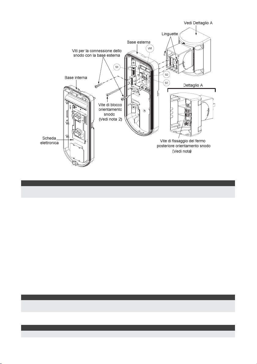
Figura 7
Nota:
Per fissare la base del rivelatore allo snodo non usare la vite che blocca il fermo posteriore dello snodo. Questa
vite non va usata poichè serve solo per il blocco dello snodo una volta orientato come desiderato.
9. Fissare la base esterna allo snodo con due viti tramite le predisposizioni S1 e S2 (figura 7).
10. Inserire nello snodo standard la vite (fornita) di fissaggio ad angolo facendola passare dalla
base esterna attraverso il foro a sfondare S3 (figura 7).
11. Orientare orizzontalmente e verticalmente lo snodo fino ad ottenere la posizione desiderata e
poi stringere la vite di blocco orientamento snodo.
12. Infilare la base interna nella base esterna ed inserire tutti i cavi attraverso la base interna.
13. Fissare la base interna a quella esterna (fissare I1, figura 2).
14. Per regolare lo snodo standard quando viene installata la scheda elettronica (figura 7):
a. Spostare la gomma nera situata sulla scheda elettronica sotto al LED rosso (quanto
basta per raggiungere la vite di blocco dello snodo).
b. Utilizzare un cacciavite per svitare la vite di blocco (vedi figura 8).
c. Orientare orizzontalmente e verticalmente lo snodo fino ad ottenere la posizione
desiderata.
d. Stringere la vite di blocco orientamento snodo.
Nota:
Quando i punti marcati delle due parti mobili sono allineati (figura 8), lo snodo standard si trova in posizione 0°.
Ogni “click” verticale da questa posizione corrisponde ad un incremento / decremento di 5°.
15. Chiudere il coperchio frontale (fissare C1, figura 1) e proseguire con la prova di movimento
per verificare l’area di copertura del rivelatore.
Nota:
La vite deve passare attraverso la base esterna ed essere fissata allo snodo.
26 Manuale di installazione WatchOUT 315DT
Page 27
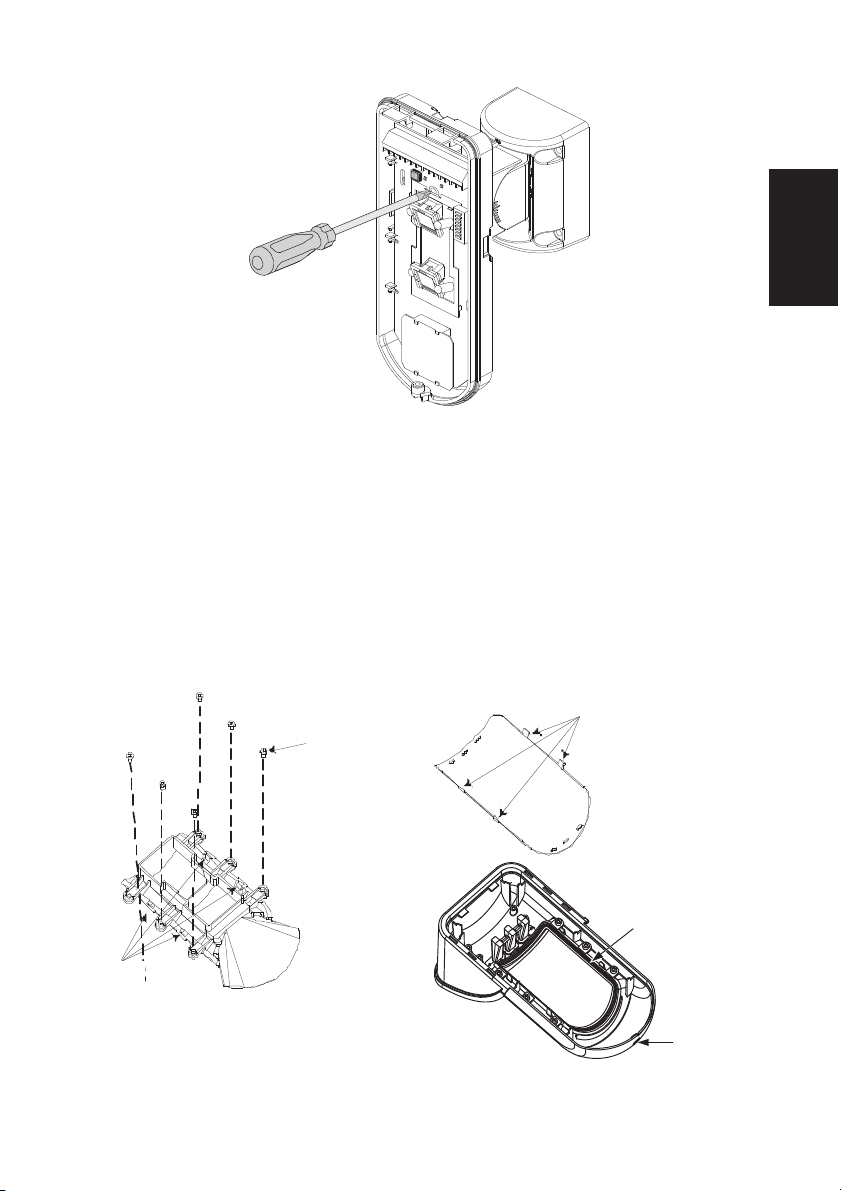
Figura 8
Sostituzione delle Lenti
1. Nella parte interna del coperchio frontale svitare le sei viti che mantengono il supporto lenti.
2. Per sganciare il supporto delle Lenti effettuare una leggera pressione sulle lenti dalla parte
anteriore del coperchio.
3. Sganciare le Lenti dal supporto facendo leggermente leva sulle clip laterali delle Lenti.
4. Sostituire le Lenti. Inserire le 4 clip delle Lenti negli appositi fori del supporto.
5. Inserire il supporto delle Lenti nel coperchio frontale del rivelatore. Prestare particolare
attenzione a riposizionare il supporto esattamente sopra la guarnizione di gomma, verificando
che anche la lente utilizzata per la protezione verticale dell’unità abbia la guarnizione
correttamente posizionata.
6. Fissare il supporto tramite le 6 viti.
Viti di fissaggio
supporto
Clip di
blocco Lenti
Italiano
Fori per clip
di blocco
Lenti
Supporto Lenti
Guarnizione
Vite di
fissaggio
coperchio
frontale
Manuale di installazione WatchOUT 315DT 27
Page 28
Tipologie di Lenti
Grandangolo (RL300) /
Discriminazione animali –
Installazione bassa (RL300F) :
Vista dall’alto
11
9
7
5
3
1
0
1
3
5
7
9
11
2468100121415
Altezza di
installazione
tipica 2.2m
Discriminazione animali – Installazione bassa
Altezza di
90°
installazione
tipica 1.5m
Nota:
L’immunità agli animali del rivelatore (altezza di un animale, nessuna limitazione di peso), è fino a 70 cm,
quando viene installato il rivelatore a 2.2m. Se l’installazione è al di sotto di questa altezza, l’immunità agli
animali diminuisce proporzionalmente; ogni 10 cm di diminuzione dell’altezza di installazione fa si che
l’immunità agli animali diminuisca di 10 cm.
Lenti Lunga Portata (RL300LR):
Vista dall’alto
1
0
1
Metri
2468100 1214161820 2223
Lenti Lunga Portata (RL300LR):
Altezza di
install azione
tipica 2.2m
Metri
3
1
0
Vista laterale
2468100 12141618202223
Grandangolo (RL300):
Vista laterale
3
1
0
Metri
2468100121415
(RL300F) :
Vista laterale
2
1
0
Metri
2468100121415
Lenti Barriera (RL300B):
Metri
1
0
1
5°
Lenti Barriera (RL300B):
Altezza di
installazione
tipica 2.2m
Vista dall’alto
2468100121415
Vista laterale
3
1
0
Metri
2468100121415
5°
28 Manuale di installazione WatchOUT 315DT
Page 29
Caratteristiche Tecniche
Elettriche
Assorbimento di corrente 30mA a 12 Vcc (a riposo)
Requisiti di alimentazione 9 -16 Vcc
Contatti di Allarme 24 Vcc, 0.1 A
Contatti Antimascheramento 24 Vcc, 0.1 A
Uscita “Lenti Sporche” Collettore aperto 70mA max.
Fisiche
Dimensioni LxWxD 230 x 123 x 123mm
Peso 0.632 Kg
Ambientali
Immunità RF Conforme alla normativa EN50130-4
Temperatura di
Funzionamento/Stoccaggio
* La tecnologia di rilevazione PIR è limitata in condizioni ambientali critiche.
42mA a 12 Vcc (max. con LED illuminati)
Da -30°C a 60°C
Informazioni per l’ordine
Unità standard
Modello Descrizione
WatchOUT 315DT WatchOUT DT + snodo
Nota:
Ogni rivelatore include lo snodo standard e 3 Lenti:
Discriminazione animali per installazioni basse fino a 1.7m (RL300F), Lunga portata (RL300R) e Barriera
(RL300B). (I codici prodotto sono marcati sulle Lenti)
Kit Accessori
Modello Descrizione Peso
RA300B kit snodo per protezione a barriera 0.1 Kg
RA300P kit adattatore da palo 0.25 Kg
RA300C kit adattatore per tubo elettrico 0.6 Kg
RA300HS contenitore demo WatchOUT - RA300SC adattatore metallico per tubo elettrico per il montaggio con
snodo
Opzioni Telecamera
Modello Descrizione
WatchOUT VC1 coperchio WatchOUT comprensivo di staffa per telecamera
WatchOUT VC017 kit telecamera grandangolo
WatchOUT VC053 kit telecamera lunga portata
WatchOUT VCPS alimetatore 220V per telecamera
WatchOUT VCPS alimentatore 120V per telecamera
1Kg
Italiano
Manuale di installazione WatchOUT 315DT 29
Page 30
Installazione in modalità BUS
Introduzione
Le informazioni di questa sezione fanno riferimento all’installazione del WatchOUT 315DT
collegato via BUS ai sistemi ProSYS di RISCO. Si possono installare fino a 32 rivelatori connessi
al BUS RS-485 della centrale ProSYS risparmiando così tempo per la stesura dei cavi e
ottenendo il vantaggio di poter configurare e testare questi rivelatori sia elettricamente che
funzionalmente, in locale o da postazione remota.
Cablaggio morsettiera
+,-
YELLOW
GREEN
TAMPER
LED
ENABLE
Nota:
I morsetti non descritti in tabella non vengono utilizzati nella modalità di connessione BUS.
Tamper Antiapertura e Antirimozione
BUS
ProS YS
COM
AU X
BLK
RED
Utilizzati per l’alimentazione 12Vcc del rivelatore. Collegare questi morsetti (+)
e (–), rispettivamente ai morsetti AUX RED e COM BLK della centrale ProSYS.
Usato per la comunicazione dei dati via bus ProSYS. Collegare questo
morsetto al BUS YEL della ProSYS.
Usato per la comunicazione dei dati via bus ProSYS. Collegare questo
morsetto al BUS GRN della ProSYS.
Usato per il cablaggio del circuito antimanomissione. Consultare gli schemi che
seguono.
Usato per il cablaggio del circuito antimanomissione. Consultare gli schemi che
seguono.
Solo Tamper Antiapertura
Modalità BUS
Cablaggio tamper
Antiapertura e Antirimozione
Cortocircuitare
BUS
YEL
GRN
TAMPER ANTIRIMOZIONE(N.C)
BUS
ProSY S
COM
AUX
BUS
BLK
RED
YEL
GRN
Cortocircuitare
Modalità BUS
Cablaggio Tamper
Antiapertura
+-
ALARM
TAMPER
GRE EN
FREE
FREE
YEL
LEDs
AM
ENA BLE
DUST TEST
UNS ET
SET/
+-
ALARM
TAMPER
FREE
YEL
GREEN
Tamper Antiapertura ad un Ingresso di Zona
BUS
ProSYS
COM
AUX
BLK
RED
+-
Ingresso
Zona
BUS
YEL
GRN
ALARM
FREE
YEL
COM
Z1 Z2
TAMPER
Modalità BUS
Tamper Antiapertura tramite
ingresso di zona
Cortocircuitare
GR EE N
FREE
LEDs
AM
DUST TEST
ENA BLE
UNSE T
SET/
30 Manuale di installazione WatchOUT 315DT
FREE
LEDs
AM
ENAB LE
DUS T TES T
UNS ET
SET/
Page 31

Predisposizione microinterruttori
N°
Microint.
1 - 5 Usati per impostare l’indirizzo ID del rivelatore. Impostare l’indirizzo ID del
6 - 8 Non usati
Indirizzo ID WatchOUT ID: Microinterruttori 1 - 5
ID 1 2 3 4 5 ID 1 2 3 4 5
01 OFF OFF OFF OFF OFF 17 OFF OFF OFF OFF ON
02 ON OFF OFF OFF OFF 18 ON OFF OFF OFF ON
03 OFF ON OFF OFF OFF 19 OFF ON OFF OFF ON
04 ON ON OFF OFF OFF 20 ON ON OFF OFF ON
05 OFF OFF ON OFF OFF 21 OFF OFF ON OFF ON
06 ON OFF ON OFF OFF 22 ON OFF ON OFF ON
07 OFF ON ON OFF OFF 23 OFF ON ON OFF ON
08 ON ON ON OFF OFF 24 ON ON ON OFF ON
09 OFF OFF OFF ON OFF 25 OFF OFF OFF ON ON
10 ON OFF OFF ON OFF 26 ON OFF OFF ON ON
11 OFF ON OFF ON OFF 27 OFF ON OFF ON ON
12 ON ON OFF ON OFF 28 ON ON OFF ON ON
13 OFF OFF ON ON OFF 29 OFF OFF ON ON ON
14 ON OFF ON ON OFF 30 ON OFF ON ON ON
15 OFF ON ON ON OFF 31 OFF ON ON ON ON
16 ON ON ON ON OFF 32 ON ON ON ON ON
Descrizione
rivelatore così come per ogni altro modulo PROSYS. Consultare il manuale di
“Installazione e Programmazione”, sezione di “Configurazione degli Indirizzi ID
dei Moduli”. (Fare riferimento alla tabella che segue)
Programmazione ProSYS
La sezione che segue descrive le opzioni software aggiuntive che riguardano la programmazione
del WatchOUT DT come rivelatore indirizzato su BUS. Si possono aggiungere al sistema ProSYS
fino a 32 rivelatori indirizzati su BUS (16 per la ProSYS 16) ed ognuno di essi prende il posto di
una zona del sistema. Si consiglia di leggere attentamente i manuali di Installazione e Utente
ProSYS prima di programmare il WatchOUT.
Note:
WatchOUT è compatibile con i sistemi ProSYS Versione software 4.xx e successive la funzione
Antiavvicinamento, via BUS dalla versione 7.xx.WatchOUT può essere programmato via software di
Teleassistenza Rokonet Versione 2.xx e successive.
Per avere la massima stabilità del sistema è consigliabile NON superare la distanza massima di cablaggio di
300 metri calcolati sommando tutte le diramazioni del BUS di Espansione. Per distanze maggiori consultare il
manuale di “Installazione e Programmazione ProSYS” alla sezione “Note sui Cavi da utilizzare”.
Aggiunta e Cancellazione del WatchOUT DT
WatchOUT è parte di una nuova categoria di accessori ProSYS chiamati Zone-BUS quindi,
Aggiungere o Cancellare dal sistema un WatchOUT è una procedura identica a quella effettuata
per qualsiasi altro modulo accessorio ad eccezione del fatto che: Ogni Rivelatore BUS deve
essere assegnato a una zona del sistema.
Ogni rivelatore su BUS può essere assegnato ad una zona fisica cablata del sistema o ad una
zona virtuale.
Zona Fisica:
espansione cablata (ZE08, FZ08, ZE16).
Zona Virtuale: è una qualsiasi zona di una espansione zone BUS definita come BZ08 o BZ16.
Note:
Le espansioni zone BUS espandono il sistema senza aggiungere fisicamente espansioni. Le espansioni zone
BUS virtuali possono essere usate solo per il collegamento di rivelatori su BUS.
è una qualsiasi zona della scheda principale ProSYS (zone 1-8) o di una
Italiano
Manuale di installazione WatchOUT 315DT 31
Page 32

Per aggiungere una espansione zone BUS virtuale selezionare la tipologia BZ08 o BZ16 nella procedura di
A
A
Aggiungi Modulo espansione zone in Programmazione Tecnica (tasti rapidi [7][1][2])
1. Per Aggiungere o Cancellare un WatchOUT DT procedere come segue
1. Dalla Programmazione Tecnica selezionare il menù Accessori e quindi AGG/CANC. MDL
per aggiungere una Zona BUS: tasti rapidi [7][1][9][5].
2. Usare i tasti
/ o / per posizionare il cursore sopra il campo del
numero ID della Zona BUS da aggiungere/cancellare.
Nota:
Assicurarsi che il numero di indirizzo ID programmato sul rivelatore sia identico al numero ID selezionato
durante la fase di programmazione descritta.
3. Posizionare il cursore sul campo TIPO e usare il tasto / fino a selezionare il
modello “ODT15” per il rivelatore WatchOUT DT.
4. Premere
/ per confermare.
5. Ripetere lo stesso procedimento per eventuali altri rivelatori su BUS.
2. Assegnazione del WatchOUT DT a una zona
1. Dal menù di Programmazione Tecnica selezionare il menù Zone, poi il menù Una per Una
(tasti rapidi [2][1])
2. Digitare il numero della zona da assegnare al rivelatore.
Note:
Se si è definita una espansione zone BUS virtuale, selezionare il numero di una zona riferita a questa
espansione.
3. Selezionare le partizioni, i Gruppi, la Tipologia di zona e la Risposta.
4. Raggiunta l’opzione Terminazione selezionare [5] Zona BUS e premere
/ .
Il display mostrerà:
Z:001 ASSEGNA
ID:01 TIPO=ODT15
5. Selezionare il numero di zona BUS da assegnare alla zona che si sta programmando. Il
campo TIPO verrà automaticamente aggiornato con il modello del rivelatore.
6. Premere
/ . La RISPOSTA LOOP non è applicabile alle zone BUS quindi il
display mostrerà:
Z:001 RISP.LOOP:
FUNZ. NON USAT
7. Premere
premere
/ , e programmare una etichetta di testo alla zona poi, per finire,
/ .
3. Configurazione dei parametri del WatchOUT DT
1. Per accedere al menù di configurazione parametri del WatchOUT, premere in Prog.
Tecnica [2][0][3]. Il display mostrerà:
PARAM. Z-BUS:
ZONA= 001 (M:ZZ)
2. Selezionare la zona alla quale il rivelatore su BUS è stato assegnato e premere
/ . Adesso è possibile programmare i parametri del WatchOUT come segue:
32 Manuale di installazione WatchOUT 315DT
Page 33

t
Zone, Varie: Parametri Zone BUS
Tasti rapidi Parametro Defaul
[2][0][3][zzz]
[1]
[2][0][3][zzz]
[1][1]
[2][0][3][zzz]
[1][2]
[2][0][3][zzz]
[1][3]
[2][0][3][zzz]
[2]
[2][0][3][zzz]
[2][1]..[4]
[2][0][3][zzz]
[3]
[2][0][3][zzz]
[3][1]..[7]
[2][0][3][zzz]
[4]
[2][0][3][zzz]
[4][1]-[2]
[2][0][3][zzz]
[5]
[2][0][3][zzz]
[5][1]..[2]
[2][0][3][zzz]
[6]
[2][0][3][zzz]
[6][1]..[2]
[2][0][3][zzz]
[7]
[2][0][3][zzz]
[7][1]
[2][0][3][zzz]
[7][2]
[2][0][3][zzz]
[8]
[2][0][3][zzz]
[8][1]..[2]
LED 3 LED
Configura il funzionamento dei LED.
Off
LED disabilitati.
Solo il Rosso
Solo il LED rosso è attivo. L’opzione è consigliata per evitare che l’intruso
comprenda comportamento e aree di copertura del rivelatore.
3 LED
Tutti e tre i LED sono attivi.
Sensibilità Normale
Configura la sensibilità del rivelatore (MW + PIR)
Opzioni Sensibilità
1) Bassa
2) Media
Portata MW Trimmer
Permette di configurare la portata della sezione microonda. La portata
massima è di circa 23 metri.
Portata MW
1) Minimo
2) 20%
Sensibilità Anti-Mascheramento Bassa sensibilità
Definisce la sensibilità dell’IR attivo Anti-Mascheramento
Opzioni Sensibilità Anti-Mascheramento
1) Bassa Sensibilità 2) Alta Sensibilità
Tipologia Lenti Grandangolo
Configura il rivelatore per funzionare con il tipo di lenti installate.
Opzioni Tipologie di Lenti
1) Grandangolo 2) Barriera o Lunga Portata.
Anti-Mascheramento Abilitato
Configura l’opzione Antimascheramento del rivelatore.
Opzioni Anti-mascheramento
1) Disabilitato 2) Abilitato (Default)
Inserito/Disinserito No
Imposta il funzionamento dei LED e dell’Anti-Mascheramento quando il
sistema è inserito.
No
L’Anti-Mascheramento (IR attivo e Antiavvicinamento) è abilitato
Il funzionamento dei LED dipende dalla definizione del parametro LED
Si
L’Anti-Mascheramento (IR attivo e Antiavvicinamento) e LED disabilitati ad
impianto inserito.
Prox. AM Disabilitato
Configura l’opzione Antiavvicinamento del rivelatore.
Opzioni Prox. AM
1) Disabilitato (Default) 2) Abilitato
NOTA: Con la funzione ‘Antiavvicinamento’ abilitata e il sensore installato a
cielo aperto, si raccomanda di creare un riparo sopra di esso per evitare
allarmi impropri in presenza di forti pioggie o alternativamente disabilitare la
funzione.
3) Normale
4) Alta
3) 40%
4) 60%
5) 80%
6) Massimo
7) Trimmer (la portata è quella
impostata dal trimmer dell’unità)
Italiano
Manuale di installazione WatchOUT 315DT 33
Page 34

Parametri di Sistema
t
Sistema: Controlli SIS
Tasti rapidi Parametro Defaul
[1][2][36]
[1][2][37]
Diagnostica
ProSYS permette la diagnostica dei parametri che determinano di funzionamento del rivelatore
WatchOUT.
1. In tastiera, con il display nel modo normale di funzionamento, premere I tasti
accedere al menù Manutenzione.
2. Inserire il codice Tecnico (o il codice sub-tecnico) e premere
3. Premere [9] [1] per accedere al menù di Diagnostica Zone.
4. Selezionare la zona che si vuole testare premere
della zona e il display mostrerà una lista di parametri riportati e spiegati nella tabella che
segue.
5. Usare i tasti
risultati dei test.
Menù Funzioni Utente: 4) Manutenzione 9) Diagnostica 1) Zone BUS
Tasti rapidi Parametro
[4][9][1][zzz] Alimentaz.: Visualizza la tensione di alimentaz. del rivelatore.
IR AM=Tamper No
Utilizzato per determinare la risposta del sistema alla rilevazione di un
mascheramento.
Si: Anti-mascheramento come allarme tamper.
No: Anti-mascheramento come anomalia.
Prox AM =Tamper No
Usato per determinare il modo di risposta del Sistema in caso di
un’attivazione dell’Antiavvicinamento
Si: L’attivazione dell’Antiavvicinamento genererà un allarme tamper
No: L’attivazione dell’Antiavvicinamento genererà una condizione di guasto
nel sistema.
[4] per
/ .
/ . Il sistema effettuerà il test
/ / per scorrere la lista di parametri e verificare i
Liv. PIR 1: visualizza il livello di segnale in tensione continua del PIR 1. (0.1v
– 4v).
Rumore PIR 1: visualizza il livello di rumore in tensione alternata del PIR 1.
(0Vca (Nessun rumore) – 4Vca).
Liv. PIR 2: visualizza il livello di segnale in tensione continua del PIR 2. (0.1v
– 4v).
Rumore PIR 2: visualizza il livello di rumore in tensione alternata del PIR 2.
(0Vca (Nessun rumore) – 4Vca).
Livello MW 1: visualizza il livello di rumore in tensione continua del canale
MW1. (0.1v – 4v).
Rumore MW 1: visualizza il livello di rumore in tensione alternata del canale
MW 1 (0Vca (nessun rumore) – 4Vca).
Livello MW 2: visualizza il livello di rumore in tensione continua del canale
MW2. (0.1v – 4v).
Rumore MW 2: visualizza il livello di rumore in tensione alternata del canale
MW 2 (0Vca (nessun rumore) – 4Vca).
34 Manuale di installazione WatchOUT 315DT
Page 35

Índice de Contenidos
Instalación en Modo Relé ..................................................................................................... 36
Introducción .......................................................................................................................... 36
Montaje ................................................................................................................................. 36
Consideraciones de Montaje .............................................................................................. 36
Instalación de Montaje en Pared ........................................................................................ 37
Montaje en pared: .............................................................................................................. 37
Montaje en ángulo de 45° (montaje del lado izquierdo) ...................................................... 37
Cambiando la posición del Tamper Posterior ..................................................................... 38
Cableado de los terminales .................................................................................................... 38
Configuración de los interruptores DIP ................................................................................. 39
Ajuste del Microondas ........................................................................................................... 39
Prueba de paseo ................................................................................................................ 39
Visualización de los LEDs ....................................................................................................... 40
Puente Modo Relé / Modo BUS ............................................................................................. 40
Instalación del Soporte con Rótula Giratoria Estándar .......................................................... 40
Montaje en Pared ............................................................................................................... 40
Montaje del Adaptador a tubo del Soporte con Rótula Giratoria ......................................... 41
Cambio de las Lentes ............................................................................................................. 43
Tipos de Lente ................................................................................................................... 44
Especificaciones Técnicas ....................................................................................................... 45
Información para Pedidos ...................................................................................................... 45
Instalación en Modo BUS ..................................................................................................... 46
Introducción .......................................................................................................................... 46
Cableado de los terminales .................................................................................................... 46
Configuración de los interruptores DIP ................................................................................. 46
Programación de las centrales ProSYS ................................................................................... 47
Parámetros del Sistema ......................................................................................................... 49
Español
Manual de Instalación del WatchOUT 315DT 35
Page 36

Instalación en Modo Relé
Introducción
El detector de Exterior de Doble Tecnología de RISCO Group, WatchOUT 315DT, es un detector
único con tratamiento de señal basado en dos canales Infrarrojos Pasivos (PIR) y en dos canales
de Microondas (MW). El detector puede funcionar como un detector de relé normal conectado a
cualquier panel de control, o como un accesorio en BUS cuando se conecta al panel de control
ProSYS de RISCO Group a través del BUS RS485, teniendo así capacidades únicas de control
remoto y diagnóstico.
Las siguientes instrucciones describen el WatchOUT 315DT en modo Relé y BUS. Para
información detallada de la instalación en modo BUS, ver el capítulo Instalación en Modo Bus
.
Montaje
Consideraciones de Montaje
1m - 2.7m
(3'3" - 8'9")
Altura Opcional: 1m – 2.7m (3'3"-8'9")
Altura Típica: 2.2m (7'2")
Lentes predeterminadas: Gran angular 15m
(50') 90° (RL300)
Evitar apuntar el detector hacia objetos que
se muevan (árboles balanceándose,
arbustos,)
Nota:
1. Para instalaciones bajas de altura, por debajo
de 1.7m (5'6") en las cuales se necesite la
inmunidad contra pequeños animales, usar la
lente suministrada RL300F (instalaciones en
paredes o vallas bajas).
2. La inmunidad contra pequeños animales del
detector (altura de un animal, sin límite de
peso) es hasta 70cm (2'4"), cuando el detector
se instala a 2.2m (7'2"). Si la instalación es por
debajo de la altura mencionada arriba, la
inmunidad contra mascotas disminuye
proporcionalmente; cada reducción de 10cm
(4") en la altura de la instalación conlleva una
reducción de 10cm (4") en la inmunidad contra
mascotas (altura del animal).
En instalaciones con mucho tráfico de vehículos o blancos fuera
del rango de detección requerido, se recomienda ajustar la
sensibilidad del MW y/o inclinar el detector hacia abajo.
de un mínimo 5m (16’)
Asegurarse de que ningún objeto obstruya el
campo de visión de ambas tecnologías.
Prestar atención a los árboles o arbustos en
crecimiento, a las plantas con grandes hojas
que se mueven, etc.
5m (16')
Mantenga dis tancia
de objetos móviles
Fuera del Área
de detección
Nota:
Inclinar el detector hacia abajo puede reducir la inmunidad contra
pequeños animales.
Para conseguir una óptima
detección, seleccionar una
ubicación del detector en la que
sea probable interceptar a un
intruso moviéndose a través del
patrón de cobertura en una
trayectoria de 45°.
NOTA: Desabilite el AM de proximidad durante una lluvia intensa (si el WatchOUT 315DT esta a la
intemperie) para prevenir alertas de Proximidad AM.
36 Manual de Instalación del WatchOUT 315DT
Page 37

Instalación de Montaje en Pared
Nota:
Los números pre-marcados de instalación están
señalados en la placa posterior.
1. Abrir la tapa delantera del WatchOUT
(Desatornillar C1, Figura 1).
2. Liberar la base interna (Abrir I1, Figura 2).
3. Seleccionar la instalación de montaje como
sigue:
Montaje en Pared:
Liberar los agujeros pre-marcados en la
base externa (Figura 3).
• B1 - B4: Agujeros pre-marcados de
montaje en pared
• T1: Agujero pre-marcado del tamper
trasero
• W2 / W3: Agujeros pre-marcados para
entrada de cables
Montaje en ángulo de 45° (montaje del
lado izquierdo)
a. Abrir los agujeros pre-marcados en la
base externa (Figura 3)
• L1, L2: Agujeros pre-marcados de
montaje del lado izquierdo
• T3: Agujero pre-marcado del tamper
izquierdo
• W5 / W6: Agujeros pre-marcados para
entrada de cables
b. Quitar el resorte del tamper
c. Reemplazar la abrazadera del tamper
(Ítem 1) con la abrazadera plana
suministrada (Ítem 2).
Ítem 1
d. Insertar la palanca del tamper B en T5 y
T3 y apretar el tornillo A (Figura 3)
4. Pasar los cables externos a través de la
base externa W2, W3 (montaje plano) o
W5, W6 (montaje lado izquierdo) (Figura 3)
5. Fijar la base externa a la pared.
6. Pasar los cables externos y los cables del
tamper a través de la base interna (Figura
4).
7. Fijar la base interna a la base externa
(cierre I1, Figura 2).
8. Cerrar la tapa delantera (cierre C1, Figura
1) después de cablear y configurar los
interruptores DIP.
9. Realizar una prueba de paseo del detector.
Ítem 2
Figura 1
Figura 3
Palanca del
Tamper
B
A
Figura 4
Figura 2
C1
T1
T3
L1
B1
W5
W6
W3
L2
B4
l1
Español
T5
T6
T4
T2
R1
(no visible)
B2
W9
W2
R2
(no visible)
B3
Manual de Instalación del WatchOUT 315DT 37
Page 38

Nota:
Para la instalación del lado derecho a 45° usar lo equivalente en la base externa como sigue:
Descripción agujeros pre-marcados Izquierda Derecha
Agujeros de montaje L1, L2 R1, R2
Agujeros del resorte del tamper T1,T3 T2,T4
Anclaje del tornillo del tamper T5 T6
Agujeros de cableado W5, W6 W7, W8
Cambiar la posición del Tamper Posterior
El tamper posterior, por defecto, se asegura en el
lado derecho de la base (vista posterior). Si
desea moverlo al lado izquierdo (vista posterior),
haga lo siguiente (Figura 5):
1. Quitar el tornillo 1 del tamper para liberar el
tamper de la posición 7.
Figura 5
1
Tamper del Lado
Izquierdo
6
3
Tamper del Lado
Derecho
7
2. Asegurarse de que el resorte 2 del tamper está
asentado sobre la base del cable del tamper 4.
3. Asegurarse de que la abrazadera de plástico
del tamper 3 esté asentada en el 2 y 4.
4. Colocar el tornillo del tamper 1 en el 3 sobre la
4
2
5
posición 6.
Notas:
1. Asegurarse de escuchar un "clic" al fijar el resorte del tamper a la pared.
2. Para instalación en poste, el tamper puede moverse a la parte inferior del lado derecho de la base interna.
Cableado de los terminales
12VDC
+-
+,ALARM
FREE YEL
TAMPER
FREE
GREEN
AM
ALARM
N.C
FREE
YEL
TAMPER
N.C
FREE
GREEN
LEDs
AM
ENABL
WatchOUT DT - PCB
12 VCC
Relé N.C., 24 VCC, 0.1A
Este terminal está libre y puede ser usado para conectar cables y resistencias
EOL (final de línea)
Relé N.C., 24 VCC, 0.1A
Este terminal está libre y puede ser usado para conectar cables y resistencias
EOL (final de línea)
Salida de relé de AM normalmente cerrada (24 VCC, 0.1A) indica alarma Anti-
DUST TEST
SET/
UNSET
Enmascaramiento o cualquier problema en el detector (a excepción de
polvo/lente sucia).
El AM de Proximidad permite recibir alertas de sabotaje antes de que el detector
sea enmascarado o dañado, utilizando los dos canales de microondas.
Nota:
Cuando el DIP8 está en la posición ON, este relé también se abre durante un breve periodo
LED
ENABLE
de tiempo cuando se produce un intento de enmascaramiento por Proximidad.
Usado para controlar remotamente los LEDs cuando el DIP1 está en ON.
Activado: entrada de +12V (function OR) sin conexión al terminal
Desactivado: conectar la entrada a 0V
DUST Colector NA (normalmente abierto), máx. 70 mA. Indica que la lente está sucia y
requiere limpieza.
38 Manual de Instalación del WatchOUT 315DT
Page 39

TEST
fOff
SET/
UNSET
Usado para realizar pruebas remotas de alarma al detector, aplicando 0 voltios a
este terminal.
Test OK: El Relé de alarma se abre momentáneamente.
Fallo: Se abre la salida AM.
Esta entrada permite habilitar o deshabilitar el Anti-enmascaramiento y los
LEDs, según el estado del sistema: Armado o Desarmado.
Cuando el sistema está armado, esta función impide a un intruso conocer el
estado del detector y desactiva la detección Anti-enmascaramiento.
Estado del Sistema Estado de la entrada Relé AM LEDs
Armado 0V Of
Desarmado 12V o sin conexión On* On**
* DIP7 está en ON (Anti-enmascaramiento habilitado)
** DIP1 en ON (LEDs activados) y el terminal de entrada LEDs ACTIVADO está activado
(+12V, o sin conexión al terminal)
Configuración de los interruptores DIP
O
N
O
2
1
6
5
4
3
DIP 1: Funcionamiento de los LEDs
8
7
Predeterminado
de Fábrica
On: LEDs Activados
Off: LEDs Desactivados
DIP 2-3: Sensibilidad de Detección
Sensibilidad DIP2 DIP3
Baja Off Off
Media Off On
Normal
On Off
(Predeterm.)
Máxima* On On
* En la máxima sensibilidad el
reconocimiento de oscilación se
desactiva para alcanzar el máximo
de sensibilidad
DIP 4: Sensibilidad Anti-enmascaramiento
On: Alta
Off: Baja
DIP 5: Óptica del detector
On: Barrera / Largo alcance
Off: Gran angular
DIP 6: LED Rojo / 3 LED
On: Sólo LED rojo
Off: 3 LEDs
DIP 7: Funcionamiento Anti-enmascaramiento
On: Habilitado
Off: Deshabilitado
DIP 8: AM de Proximidad
On: Habilitado
Off: Deshabilitado
Ajuste del Microondas
Ajustar el área de cobertura del Microondas usando el potenciómetro
de la PCB (placa de circuito impreso).
Prueba de paseo
Dos minutos después de aplicar alimentación, hacer la prueba de
paseo en el área protegida para verificar su correcto funcionamiento.
En instalaciones en superficies desniveladas, deslice el PCB dentro
de la base interna al ajuste apropiado según la altura deseada (1.0m,
1.5m, 2.2m, 2.7m) como está impreso en la esquina inferior izquierda
del PCB o use el soporte con rótula giratoria estándar.
Para reducir el alcance de detección, deslizar el PCB hacia arriba
inclinar el soporte con rótula giratoria hacia abajo
. Tenga en cuenta
que al hacer esto la inmunidad contra pequeños animales puede
verse reducida.
o
MIN
MAX
PCB
1.00M
1.50M
2.20M
2.70M
Español
Manual de Instalación del WatchOUT 315DT 39
Page 40

Visualización de los LEDs
LED Estado Descripción
YELLOW
GREEN
RED
Todos los
LEDs
Notas:
1. El interruptor DIP 1 debe estar en la posición ON para habilitar las indicaciones del LED.
2. Solamente un LED está activo al mismo tiempo. Por ejemplo, en el caso de detección simultánea PIR y MW,
se visualiza de forma constante el LED AMARILLO o el VERDE (el primero que detecta), seguido del LED
ROJO de Alarma.
3. A fin de evitar que se analicen cómo funcionan las tecnologías de detección de una Alarma, AntiEnmascaramiento o AM de Proximidad, colocar el interruptor DIP 6 (SW1) en posición ON. De esta manera
sólo se activará el LED rojo.
Puente Modo Relé / Modo BUS
El Puente J-BUS (situado en el PCB entre los LEDs rojo y
verde) se usa para definir el modo de funcionamiento del
detector, de la siguiente manera:
Encendido Indica detección del PIR
Parpadea Indica detección de AM (Anti-enmascaramiento)
Encendido Indica detección del MW
Parpadea Indica detección de AM de Proximidad
Encendido Indica ALARMA
Parpadea Indica fallo en la comunicación con la central ProSYS (sólo
en el modo BUS)
Parpadean (uno
Inicialización de la unidad al encender.
después de otro)
Modo Relé Modo BUS
O
N
O
N
Instalación del Soporte con Rótula Giratoria Estándar
El detector de Exterior se entrega con un soporte con rótula giratoria estándar para permitir una
mayor flexibilidad en la instalación. Por favor, siga las instrucciones indicadas a continuación para
montar el detector con el Soporte con Rótula Giratoria Estándar:
1. Abrir la tapa delantera del WatchOUT (Desatornillar C1, Figura 1).
2. Liberar la base interna (liberar I1, Figura 2).
3. Abrir los agujeros pre-marcados en la base externa (Figura 6, Detalle B)
• W1: Agujeros pre-marcados para los cables
• S1,S2: Agujeros pre-marcados para asegurar la base externa al Soporte con Rótula
Giratoria Estándar
• S3: Agujero para el tornillo de fijación de la base externa
4. En el soporte con rótula giratoria rompa el agujero pre-marcado que necesite para pasar el
cableado por la rótula: S2, S7 o S9 (Figura 6, Detalle A).
5. Extraer el tamper posterior de la base interna (ver el apartado “Cambiar la Posición del
Tamper Posterior ") y conectarlo a S5 (Figura 6, Detalle A) en el Soporte con Rótula
Giratoria Estándar.
Nota:
Asegurarse de ver la marca grabada UP en la parte superior del frontal del Soporte con Rótula Giratoria.
6. Seleccionar el tipo de montaje de instalación como se indica a continuación:
Montaje en Pared
a. Pasar el cable externo a través de los agujeros pre-marcados S2, S7 o S9 (incluyendo los
cables del tamper) a través del Conducto de los Cables del Soporte con Rótula Giratoria
(Figura 6, Detalle B).
b. Fijar el soporte con la rótula giratoria a la pared a través de los agujeros S1, S3, S6 y S8.
40 Manual de Instalación del WatchOUT 315DT
Page 41

Montaje del adaptador a tubo en el Soporte con Rótula Giratoria (usando el Adaptador
metálico de tubo del Soporte con Rótula Giratoria - CSMA, Figura 6, Detalle A).
Agujeros del
Resorte del
Tamper
Detalle A
CSMA
M1
M1
M1
M1
Ø
16 mm
21mm
Ø
Rótula Estándar
S1
S9
S8
Conducto de
cables del
eslabón giratoriode
la Rótula
S2
S3
S7 S6
(véase ver Detalle C)
S4
S5
Tamper
S1
Detalle B
W1
Clips de
sujección
S2
S3
Detalle C
Figura 6
Nota:
El CSMA es necesario cuando el cableado va por un tubo no empotrado en la pared y se necesita proteger los
cables. El CSMA debe pedirse por separado – Ref. RA300SC0000A.
a. Elegir la orientación del CSMA según el diámetro necesario: 16mm (0.63 pulgadas) ó 21mm
(0.83 pulgadas).
b. Insertar el tubo eléctrico al CSMA.
c. Fijar el CSMA a la pared a través de los puntos (M1, M4).
d. Introducir los cables externos y los cables del tamper que llegan del tubo eléctrico
haciéndolos pasar a través del paso de cables del soporte con rótula giratoria (Figura 6,
Detalle A).
e. Fijar el soporte con rótula giratoria a la pared mediante los agujeros S1, S3, S6 y S8.
Nota:
El resorte del tamper S5 (Figura 6, Detalle A) debe hacer contacto con la pared a través de los agujeros de los
resortes del tamper M2 o M3 en el CSMA. Asegurarse de ello al oír el "Clic" del interruptor del tamper al fijar el
dispositivo a la pared.
7. Pasar los cables del tamper y los cables de conexión que llegan del Soporte con Rótula
Giratoria a través del agujero pre-marcado W1 en la base externa (Figura 6, Detalle B).
8. Conectar la base externa del detector al soporte con rótula giratoria mediante los
correspondientes clips (Figura 7).
Español
Manual de Instalación del WatchOUT 315DT 41
Page 42

Tornillos de Conexión de
la Rótula a la Base
Base Interna
Externa
Tornillo de
Fijación
del Ángulo
(Ver nota 2)
S1
Base Externa
Véase
Detalle A
Clips a
presión
W1
S2
S3
Detalle A
PCB
Figura 7
Tornillo de Conexión para
Montaje de la Rótula
(Véase nota)
Nota:
Para fijar la base del detector al soporte con rótula giratoria no utilizar el tornillo que bloquea el giro posterior de
la rótula del soporte. Dicho tornillo solamente sirve para bloquear la rótula una vez que el detector haya sido
orientado a su campo de detección.
9. Fijar la base externa del detector al soporte con rótula giratoria mediante los 2 tornillos de
los orificios pre-marcados S1 y S2 (Figura 7).
10. Insertar en el soporte con rótula el tornillo de fijación en ángulo, que se suministra con el
detector, haciéndolo pasar por el orificio pre-marcado S3 (Figura 7).
11. Orientar horizontal y verticalmente el Soporte con Rótula Giratoria Estándar a la posición
deseada. Una vez que la Rótula Giratoria Estándar esté en la posición deseada, apretar el
tornillo de fijación del ángulo.
12. Alinear la base externa del detector con la base interna y hacer pasar todos los cables por
dicha base interna.
13. Asegurar la base interna a la base externa (Cierre I1, Figura 2).
14. Para volver a orientar el Soporte con Rótula Giratoria Estándar cuando el circuito impreso
PCB está instalado (Figura 8) hacer lo siguiente:
a. Levantar la espuma negra situada debajo del LED ROJO en el PCB (lo suficiente para
acceder al tornillo de fijación del Soporte con Rótula Giratoria).
b. Utilizar un destornillador de estrella para liberar el tornillo de fijación (ver Figura 8).
c. Orientar el Soporte con Rótula Giratoria Estándar hasta la posición deseada.
d. Apretar el tornillo de fijacíon de la rótula.
Nota:
Cuando las marcas de las dos partes móviles están alineadas (Figura 8), el Soporte con Rótula Giratoria
Estándar estará en la posición vertical / horizontal 0º. Cada señal desde esta posición representa un
desplazamiento de 5º en la posición vertical / horizontal.
15. Cerrar la tapa frontal (Cierre C1, Figura 1) y hacer una prueba de paseo del detector.
42 Manual de Instalación del WatchOUT 315DT
Page 43

Nota:
El tornillo debe pasar a través de la Base Externa y fijarse al Soporte con Rótula Giratoria.
Figura 8
Cambio de las Lentes
1. Aflojar y quitar los seis tornillos de la parte posterior de la tapa frontal del detector que
mantienen la funda protectora de la lente.
2. Empujar suavemente la lente desde el lado externo de la tapa delantera para liberar la funda
protectora.
3. Desenganchar la lente de la funda empujando suave y lateralmente los clips de fijación que
la sujetan a la funda.
4. Sustituir la lente. Colocar los 4 clips de la lente en los agujeros apropiados en la funda.
5. Volver a insertar la funda protectora en su lugar en la tapa delantera. Poner atención al
colocar la funda sobre la goma de sellado.
6. Fijar el soporte apretando los 6 tornillos colocados de nuevo en su lugar.
Tornillos de
fijación de la
Funda
Clips de Fijación
de la Lente
Español
Goma de
sellado
Funda Protectora de la
Lente
Tornillo de
Agujeros para los
clips de la lente
Fijación de la
Tapa Delantera
Manual de Instalación del WatchOUT 315DT 43
Page 44

Tipos de Lentes
0
Lente gran angular (RL300) /
Lente para instalación baja -
Mascotas (RL300F) :
40
30
20
10
0
10
20
30
40
Vista superior
11
9
7
5
3
1
0
1
3
5
7
9
11
2468100121415
20
10
0
30 40 50
90°
Instalación
2.2 m (7'2")
Lente para instalación baja - Mascotas (RL300F)
Instalación
Típica
Altura :
1.5 m (5'3 ")
Nota:
La inmunidad del detector contra pequeños animales (depende de la altura del animal, sin límite de peso) es
hasta 70cm (2'4"), cuando el detector se instala a 2.2m (7'2"). Si la instalación se realiza por debajo de la altura
mencionada arriba, la inmunidad contra Mascotas disminuye proporcionalmente; cada reducción de 10cm (4")
en la altura de la instalación conlleva una reducción de 10cm (4") en la Inmunidad a las Mascotas (altura del
animal).
Lente de largo alcance (RL300LR):
Vista superior
Pies
1
3
0
0
3
1
Metros
2468100 12141618202223
Pies
0
20
10
30 40 50
60 70 75
Lente de largo alcance (RL300LR):
Instalación
Típica
Altura:
2.2m (7'2")
Pies
10
0
Metros
Pies
3
1
0
0
Vista lateral
246810012141618202223
20
10
30 40 50
60 70 75
Lente gran angular (RL300):
Vista lateral
Pies
10
0
Meters
Pies
3
1
0
2468100121415
10
0
Típica
Altura :
Vista lateral
Pies
6
2
1
0
0
Meters
Pies
2468100121415
10
0
Lente de barrera (RL300B):
Pies
3
1
5°
0
0
3
1
Meters
2468100121415
Pies
10
Lente de barrera (RL300B):
Instalación
Típica
Altura:
2.2m (7'2")
0
Pies
10
3
1
0
0
Meters
Pies
0
20
30 40 50
20
30 40 50
Vista superior
20
04050
3
Vista lateral
2468100121415
20
10
30 40 50
5°
44 Manual de Instalación del WatchOUT 315DT
Page 45

Especificaciones Técnicas
Eléctrica
Consumo de corriente 30mA a 12 VCC (en reposo)
Requisitos de voltaje 9 -16 VCC
Contactos de alarma 24 VCC, 0.1A
Contactos AM 24 VCC, 0.1A
Salida de polvo Colector abierto 70mA máx.
Física
Tamaño:
Longitud x Anchura x Profundidad
Peso 0.632 Kg (1.4lb)
Medioambiental
Inmunidad a RF Según EN 50130-4
Temperatura de
Operación/Almacenamiento
* La tecnología PIR se ve limitada en condiciones ambientales severas.
42mA a 12 VCC (máx. con LED ON)
230 x 123 x 123mm
(8.7 x 4.5 x 4.85 in.)
-30°C a 60°C (-22°F a 140°F)
Información para Pedidos
Unidades Estándar
Modelo Descripción
WatchOUT 315DT WatchOUT DT + Rótula giratoria
Nota:
Cada uno de los detectores contiene un soporte con rótula giratoria estándar y 3 lentes (Las referencias van
grabadas en las mismas lentes): 1 lente para instalación en baja altura: 1.7m y anti-mascotas (RL300F), 1
lente de largo alcance (RL300R) y 1 lente de barrera (RL300B).
Kits de Accesorios
Modelo Descripción Peso
RA300B Kit Rótula de Barrera para WatchOUT 0.1 Kg (0.23 lb)
RA300P Kit Adaptador de Poste para WatchOUT 0.25 Kg (0.55 lb)
RA300C Kit Adaptador de Conducto para WatchOUT 0.6 Kg (1.27 lb)
RA300SC Rótula Adaptador de Conducto de Metal
para WatchOUT
Opción de Cámara
Modelo Descripción
WatchOUT VC1 Carcasa con adaptador de cámara para WatchOUT (Cámara no
incluida)
1Kg (2.2 lb)
Español
Manual de Instalación del WatchOUT 315DT 45
Page 46

Instalación en Modo BUS
Introducción
La información en esta sección se refiere únicamente a la instalación del WatchOUT 315DT en
Modo BUS. Pueden instalarse hasta 32 detectores en el BUS RS485 de las centrales ProSYS,
ahorrando tiempo de cableado y permitiendo control y diagnósticos remotos.
Cableado de los terminales
+,-
YELLOW
GREEN Usado para comunicación de datos con las centrales ProSYS. Conecte el
TAMPER
LED
ENABLE
Nota:
Todos los terminales que no se mencionan en la tabla de arriba, no se utilizan.
ProS YS
COM
AUX
BLK
RED
Usado para la conexión de la fuente de alimentación de 12 VCC. Conecte el
terminal (+) al AUX RED y el terminal (–) al COM BLK en los terminales de las
centrales ProSYS.
Usado para comunicación de datos con las centrales ProSYS. Conecte el
terminal al BUS YEL de las centrales ProSYS
terminal al BUS GRN de las centrales ProSYS
Usado para el cableado del tamper (véase más abajo)
Usado para el cableado del tamper (véase más abajo)
Tamper de Tapa y Posterior
BUS
Cableado de la Tapa y del T amper posterior
Corto
BUS
YEL
GRN
Modo BUS:
Tamper
posterior (N.C.)
Tamper de Tapa solamente
BUS
ProSY S
COM
AU X
YEL
BLK
RED
Cableado del tamper de la Tapa
BUS
GRN
Corto
Modo BUS:
+-
ALARM
FREE
FREE
TAMPER
GR EE N
YEL
LEDs
AM
ENA BL E
DUST TEST
UNSE T
SET/
+-
ALARM
FREE
YEL
TAMPER
GREEN
FREE
LEDs
AM
ENABLE
DUST TEST
UNSE T
SET/
Tamper de Tapa a Entrada de Zona
ProSYS
AUX
COM
RED
BLK
+-
BUS
Entrada de
Zona
BUS
YEL
GR N
ALARM
FREE
YEL
COM
Z1 Z2
TAMPER
Modo BUS:
Tamper de la Tapa para
Entrada de Zona
Corto
FREE
LEDs
AM
GREE N
ENA BLE
DUST TEST
SET/
UNS E T
Configuración de los interruptores DIP
Número del
Interruptor DIP
1 - 5 Usado para asignar el número de ID del detector. Establezca el número de
6 - 8 Sin uso
46 Manual de Instalación del WatchOUT 315DT
Descripción
ID de la misma manera que para cualquier otro accesorio de las centrales
ProSYS (Ver manual de instalación de las centrales ProSYS)
Page 47

WatchOUT ID: Interruptores DIP 1 - 5
ID 1 2 3 45 ID12 345
01 OFF OFF OFF OFF OFF 17 OFF OFF OFF OFF ON
02 ON OFF OFF OFF OFF 18 ON OFF OFF OFF ON
03 OFF ON OFF OFF OFF 19 OFF ON OFF OFF ON
04 ON ON OFF OFF OFF 20 ON ON OFF OFF ON
05 OFF OFF ON OFF OFF 21 OFF OFF ON OFF ON
06 ON OFF ON OFF OFF 22 ON OFF ON OFF ON
07 OFF ON ON OFF OFF 23 OFF ON ON OFF ON
08 ON ON ON OFF OFF 24 ON ON ON OFF ON
09 OFF OFF OFF ON OFF 25 OFF OFF OFF ON ON
10 ON OFF OFF ON OFF 26 ON OFF OFF ON ON
11 OFF ON OFF ON OFF 27 OFF ON OFF ON ON
12 ON ON OFF ON OFF 28 ON ON OFF ON ON
13 OFF OFF ON ON OFF 29 OFF OFF ON ON ON
14 ON OFF ON ON OFF 30 ON OFF ON ON ON
15 OFF ON ON ON OFF 31 OFF ON ON ON ON
16 ON ON ON ON OFF 32 ON ON ON ON ON
Programación de las centrales ProSYS
La sección siguiente describe las opciones de programación adicionales añadidas al software de
las centrales ProSYS, que conciernen a la configuración del WatchOUT DT como un detector en
BUS. Un sistema de seguridad realizado con las centrales ProSYS puede llevar hasta 32
detectores detectores en BUS (16 detectores en la central ProSYS 16) y cada uno de ellos
ocupará una zona en el sistema.
Es recomendable leer y comprender totalmente los Manuales de Instalación y de Usuario de las
centrales ProSYS, antes de programar el WatchOUT.
Notas:
El WatchOUT es compatible con el software de las ProSYS Versión 4.xx y superior.
El WatchOUT puede programarse a través del Software U/D a partir de la Versión 1.8 o superior.
Para una máxima estabilidad de funcionamiento, es mejor NO excederse en la distancia maxima eléctrica del
cable del BUS de 300 metros máximo (1000 pies) al conectar el WatchOUT en BUS.
Agregar / Suprimir el WatchOUT DT
El WatchOUT es parte de una nueva categoría de accesorios, de zonas en BUS. Por lo tanto,
Agregar/Suprimir el WatchOUT es idéntico a cualquier otro accesorio con la siguiente excepción:
Cada Detector de Zona BUS debe estar asignado a una Zona Regular o Convencial.
Cualquier detector en BUS puede ser asignado a una zona física cableada o a una zona virtual.
Zona Física: Cualquier zona en la placa base PCB de las centrales ProSYS (zonas 1-8) o en
un expansor de zonas cableadas (ZE08, ZE16).
Zona Virtual: Cualquier zona en un expansor de zona en BUS definida como BZ08 o BZ16.
Notas:
Las zonas virtuales en BUS son rentables. Permiten ampliar sus zonas en el sistema sin agregar expansores
físicos de zonas.
El expansor de zonas virtuales en BUS puede usarse solamente para detectores de zona en BUS.
Para agregar un expansor de zonas en BUS seleccione el tipo BZ08 o BZ16 al agregar un expansor de zonas
(Tecla rápida [7][1][2]).
1. Para Agregar / Suprimir el WatchOUT DT
1. Desde el menú de instalador entrar en el menú Agregar/Suprimir: Tecla Rápida
[7][1][9][5] para detectores de Zonas BUS.
2. Usar las teclas
ID de la Zona Bus al cual quiere asignar (o borrar) un detector.
/ o / para colocar el cursor sobre el número de
Español
Manual de Instalación del WatchOUT 315DT 47
Page 48

Nota:
Asegúrese que el número físico de ID del detector es idéntico al número de ID que se seleccionó durante la
programación.
3. Colocar el cursor en el campo TIPO y usar la tecla / para seleccionar ODT15
para el detector WatchOUT DT.
4. Pulsar
/ para confirmar.
5. Repetir el proceso para los otros detectores en BUS.
2. Asignar el WatchOUT DT a una Zona
1. En el menú principal del instalador, entrar en Zonas: opción Una a Una (Tecla rápida
[2][1])
2. Seleccionar el número de zona que se desea asignar al detector en BUS.
Nota:
Si se definió un Expansor de Zonas en BUS, seleccionar un número de zona para las zonas virtuales (definidas
por el expansor de zonas en BUS).
3. Definir Particiones, Grupos, Tipo de Zona y Sonido de Zona.
4. En la categoría Terminación seleccionar [5] Zona BUS seguido por
/ .
Entonces aparecerá la siguiente pantalla:
5. Seleccionar el número de zona BUS para asignarla a la zona programada. El campo
“tipo” se actualizará automáticamente al seleccionar la zona.
6. Pulsar
/ . La categoría BUCLE de RESPUESTA no es aplicable a una zona
BUS y aparecerá la siguiente pantalla:
7. Pulsar
/ , asignar la etiqueta de texto a la zona y pulsar / .
3. Configurar los Parámetros del WatchOUT DT
1. Para acceder a la opción de configuración del WatchOUT pulsar [2][0][3] en el menú
principal del instalador. Entonces aparecerá la siguiente pantalla:
2. Seleccionar la zona a la cual se asignó la zona BUS y presione
/ . Ahora
puede programar los parámetros del WatchOUT como se indica a continuación:
Zonas Varios: Zona BUS
Teclas Rápidas Parámetros Predeterminado
[2][0][3][zzz][1] LEDs 3 LEDs
Define el modo de operación de los LEDs.
[2][0][3][zzz]
[1][1]
[2][0][3][zzz]
[1][2]
Off
Desactiva el funcionamiento de los LEDs.
Solamente Rojo
Sólo funcionará el LED Rojo. Esta opción es altamente recomendable para
evitar la posibilidad de que el intruso “Aprenda” el comportamiento del
detector.
[2][0][3][zzz]
[1][3]
[2][0][3][zzz]
[2]
3 LEDs
Funcionarán todos los LEDs.
Sensibilidad PIR Normal
Define la sensibilidad del detector (MW + PIR)
48 Manual de Instalación del WatchOUT 315DT
Page 49

Teclas Rápidas Parámetros Predeterminado
[2][0][3][zzz]
[2][1]..[4]
[2][0][3][zzz]
[3]
[2][0][3][zzz]
[3][1]..[7]
[2][0][3][zzz]
[4]
[2][0][3][zzz]
[4][1]..[2]
[2][0][3][zzz]
[5]
[2][0][3][zzz]
[5][1]..[2]
[2][0][3][zzz]
[6]
[2][0][3][zzz]
[6][1]..[2]
[2][0][3][zzz]
[7]
[2][0][3][zzz]
[7][1]
[2][0][3][zzz]
[7][2]
[2][0][3][zzz]
[8]
[2][0][3][zzz]
[8][1]..[2]
Opciones de Sensibilidad
1) Baja
2) Media
Alcance del MW Trimmer (potenciómetro)
Define el alcance del canal de microondas. El alcance máximo es 23m.
Opciones del Alcance del MW
1) Mínimo
2) 20%
Sensibilidad Anti-Enmascaramiento Sensibilidad Baja
Define la sensibilidad del AM por IR Activo.
Opción de sensibilidad del Anti-Enmascaramiento
1) Sensibilidad Alta 2) Sensibilidad Baja
Tipo de Lente Gran Angular
Define la lente concreta del detector.
Opciones de Tipo de Lente
1) Gran Angular 2) Barrera / Largo Alcance
Anti-Enmascaramiento Activado
Define la función de detección de Anti-Enmascaramiento
Opciones de Anti-Enmascaramiento
1) Desactivado 2) Activado (Predeterminado)
Armar/Desarmar No
Define la forma de trabajo del LED anti-enmascaramiento mientras el
detector esté armado.
No
El AM (Anti-Enmascaramiento) por IR Activo y el AM de Proximidad están
activados. Los LEDs actúan según la definición de los parámetros de los
LEDs
Sí
El AM (Anti-enmascaramiento) por IR Activo y el AM de Proximidad están
desactivado
Los LEDs están desactivados
AM de Proximidad
Define la función de detección de Anti-Enmascaramiento de Proximidad.
Opciones de AM de Proximidad
1) Desactivado (Predeterminado) 2) Activado
NOTA: Desabilite el AM de proximidad durante una lluvia intensa (si el
WatchOUT 315DT esta a la intemperie) para prevenir alertas de Proximidad
AM.
3) Normal
4) Alta
3) 40%
4) 60%
5) 80%
6) Máximo
7) Trimmer (el MW es
definido por la
configuración del
potenciómetro en el PCB)
Desactivado
Español
Manual de Instalación del WatchOUT 315DT 49
Page 50

Parámetros del Sistema
Sistema: Control del Sistema
Teclas Rápidas Parámetros Predeterminado
[1][2][36] IR AM=Tamper No
Usado para determinar la indicación de la detección de AntiEnmascaramiento
Sí: La alarma de Anti-enmascaramiento activará la salida del tamper.
No: La alarma de Anti-enmascaramiento se considerará como un evento de
problema.
[1][2][37] Prox AM =Tamper No
Utilizado para determinar el funcionamiento del Anti-Enmascaramiento de
Proximidad.
Sí: El Anti-enmascaramiento de Proximidad activará la alarma de tamper.
No: El Anti-Enmascaramiento de Proximidad será considerado como un
evento de problema.
Diagnósticos
Las centrales ProSYS permiten chequear los parámetros que reflejan el funcionamiento del
detector.
1. Desde el menú principal de usuario pulsar
2. Introducir el código de Instalador (o sub-instalador) y pulsar
3. Pulsar las teclas [9] [1] para el menú diagnóstico de Zonas BUS.
4. Introducir el dígito de la zona que se quiere chequear y pulsar
realizará la prueba de diagnóstico y aparecerá una lista de parámetros, según se indica en
la tabla abajo.
5. Usar las teclas
diagnóstico.
Menú Usuario: 4) Mantenimiento 9) Diagnóstico 1) Zona BUS
Teclas Rápidas Parámetro
[4][9][1][zzz] Voltaje de Entrada del Detector: Indica el voltaje de entrada en el detector.
/ / para ver los resultados de la prueba de
PIR 1 Nivel: Canal PIR 1 nivel CC. Rango 0.1V - 4V
PIR 1 Nivel de Ruido: Canal PIR 1 nivel CA. Rango 0VAC (Sin ruido) - 4VA
PIR 2 Nivel: Canal PIR 2 nivel CC. Rango 0.1V - 4V
PIR 2 Nivel de Ruido: Canal PIR 2 nivel CA. Rango 0VAC (Sin ruido) - 4VA
MW 1 Nivel: Canal MW 1 nivel CC. Rango 0.1V - 4V
MW 1 Nivel de Ruido
MW 2 Nivel: Canal MW 2 nivel CC. Rango 0.1V - 4V
MW 2 Nivel de Ruido: Canal MW 2 nivel CA. Rango 0VAC (Sin ruido) - 4VA
: Canal MW 1 nivel CA. Rango 0VAC (Sin ruido) - 4VA
[4] para acceder al menú Mantenimiento.
/ .
/ . El sistema
50 Manual de Instalación del WatchOUT 315DT
Page 51

Table des matières
Détecteur extérieur WatchOUT 315DT : Installation en mode Relais ................................ 52
Introduction ........................................................................................................................... 52
Montage ................................................................................................................................ 52
Conditions de montage ...................................................................................................... 52
Changement de position de l'autoprotection arrière ........................................................... 54
Câblage de la borne de connexion ........................................................................................ 54
Réglage des micro-interrupteurs DIP..................................................................................... 55
Installation de la rotule standard ........................................................................................... 56
Installation murale .............................................................................................................. 56
Montage du conduit de la rotule ....................................................................................... 57
Remplacement des lentilles ................................................................................................... 59
Types de lentilles ............................................................................................................... 60
Spécifications techniques ...................................................................................................... 61
Information Catalogue ........................................................................................................... 61
Appareils Standard ................................................................................................................ 61
Détecteur extérieur WatchOUT 315DT : Installation en mode BUS ................................... 62
Introduction ........................................................................................................................... 62
Câblage du bornier ................................................................................................................ 62
Programmation de la ProSYS ................................................................................................. 63
Paramètres Système.................................................................................................................................... 66
Français
Guide d'installation du WatchOUT 315DT 51
Page 52

Détecteur extérieur WatchOUT 315DT (Double Technologie) :
Installation en mode Relais
Introduction
Le détecteur extérieur WatchOUT 315DT, de RISCO Group est un détecteur unique en son genre, doté
d'un traitement de signaux qui repose sur deux canaux à infrarouge passif (IRP) et deux canaux
HyperFréquences (HF). Le détecteur peut fonctionner soit comme détecteur relais normal relié à
n'importe quelle centrale de commande, soit comme accessoire BUS s'il est connecté à la centrale
ProSYS de RISCO Group par le BUS RS485, lui conférant ainsi des capacités exceptionnelles de
contrôle et diagnostique à distance.
Les instructions ci-dessous décrivent l'installation du WatchOUT 315DT en mode Relais. Pour plus de
détails sur l'installation en mode BUS, veuillez vous reporter aux instructions correspondantes.
Montage
Conditions de montage
1m - 2.7m
(3'3" - 8'9")
Hauteur optionnelle : 1m – 2.7m
Hauteur caractéristique : 2.2m
Lentille installée par défaut : grand angle 15m 90°
Si possible, évitez d'orienter le détecteur vers des
objets en mouvement (buissons, arbres aux branches
oscillantes etc.)
Remarque :
1. Pour les installations à faible hauteur, en
dessous de 1,7m nécessitant l'immunité aux
animaux domestiques, utilisez la lentille
RL300F fournie (pour installations sur clôture
ou mur de faible hauteur).
2. L'immunité du détecteur aux animaux
domestiques (caractérisée par la taille d'un
animal, sans limitation de poids), va jusqu'à 70
cm pour une installation du détecteur à 2,2m.
En cas d'installation en dessous de la hauteur
susmentionnée, l'immunité aux animaux
domestiques se réduit en conséquence ;
chaque abaissement de 10 cm réduit de 10 cm
l'immunité aux animaux domestiques.
Pour les installations exposées au grand trafic de véhicules ou ayant
des objectifs au-delà de la portée de détection requise, il est
recommandé de régler la sensibilité micro-ondes ou HF et/ ou d'incliner
le détecteur vers le bas.
Maint enez une distance de
5 m au moins entre le
keep distance of
minimum 5 meters (16')
détecteur et tout objet en
mouvement
Assurez-vous qu'aucun objet n'obstrue le champ de
vision des deux technologies. Prêtez attention aux
buissons ou arbres en pleine croissance, aux plantes
aux grandes feuilles souples, etc
5m (16')
With moving objects
Hors de portée
de détection
Remarque :
L'inclinaison du détecteur vers le bas est susceptible de réduire
l'immunité aux animaux domestiques.
Pour obtenir une capacité maximale de
détection, choisissez un endroit
susceptible de capter le passage de tout
intrus dans la zone couverte par les
rayons à 45°.
NOTE: Désactiver l’AM de proximité lors de fortes pluies (si le WatchOUT 315DT n’est pas à l’abri de la pluie)
pour éviter les alertes d’AM de proximité.
52 Guide d'installation du WatchOUT 315DT
Page 53

Installation murale
t
Remarque :
Pour faciliter l'installation, les pastilles pré-percées
prévues à cet effet sont numérotées sur la paroi arrière
de l'appareil.
Figure 1
1. Ouvrez le couvercle du WatchOUT (devissez
en C1, figure 1).
2. Dégagez le socle interne (devissez en I1,
figure 2).
3. Choisissez le mode d'installation comme suit
Montage à plat :
a. Percez les pastilles pré-percées du socle
externe (figure 3).
• B1-B4 : pastilles pré-percées pour
assemblage mural.
• T1 : pastille pré-percée de
l'autoprotection arrière.
• W2 / W3 : entrées pré-percées pour
fils électriques.
Montage à 45° (montage sur côté gauche)
a. Percez les pastilles pré-percées du socle
externe (figure 3).
• L1, L2 : pastilles pré-percées pour
montage à gauche
• T3 : pastille pré-percée de
l'autoprotection arrière.
• W5 / W6 : entrées pré-percées pour
fils électriques
b. Retirez le ressort de l'autoprotection.
Figure 3
Levier
d'autoprotection
A
C1
T1
T3
L1
B
B1
W5
W6
W3
c. Remplacez le crochet d'autoprotection 1
par le crochet d'autoprotection plat fourni
2.
L2
1
d. Insérez la languette d'autoprotection B aux
2
B4
endroits marqués T5 et T3, ensuite serrez
la vis A (figure 3).
4. Introduisez les fils électriques extérieurs par
Figure 4
le socle externe en W2, W3. (figure 3).
5. Fixez le socle externe de l'appareil au mur.
6. Faites passer les fils électriques externes et
d'autoprotection dans le socle interne (figure
4).
7. Fixez le socle interne au socle externe
(bloquez en I1, figure 2).
8. Fermez le couvercle (bloquez en C1, Figure
1) après avoir câblé et réglé les micro-
interrupteurs DIP.
9. Effectuez un test de passage avec le
détecteur.
Remarque :
Pour une installation à 45° sur côté droit, utilisez les pièces équivalentes du socle externe comme suit :
Désignation des pastilles pré-percées
Gauche Droi
Pastilles pré-percées pour montage L1, L2 R1, R2
Pastilles pré-percées du ressort de l'autoprotection T1,T3 T2,T4
Vis de montage de l'autoprotection T5 T6
Guide d'installation du WatchOUT 315DT 53
Figure 2
T6
l1
T5
T4
T2
R1
(Invisible)
B2
W9
W2
R2
(Invisible)
B3
Français
Page 54

Changement de position de l'autoprotection
arrière
L'autoprotection arrière est, par défaut, fixée sur
le côté droit du socle interne (vue arrière). Si vous
souhaitez la déplacer sur le côté gauche (vue
arrière), procédez comme suit (Figure 5) :
1. Retirez la vis d'autoprotection 1 pour dégager
l'autoprotection de la position 7.
Figure 5
1
Autoprotection
gauche
6
3
Autoprotection
droite
7
2. Assurez-vous que le ressort de
l'autoprotection 2 repose bien sur la base de
câblage 4 de l'autoprotection.
3. Vérifiez que le crochet en plastique 3 de
l'autoprotection repose bien sur les points 2
4
2
5
et 4.
4. Serrez la vis d'autoprotection 1 dans la pièce
3 en la faisant passer par la position 6.
Remarques:
1. Vous entendrez un "Clic" en fixant le ressort de l'autoprotection au mur.
2. Pour l'installation sur un mât, l'autoprotection peut être déplacée vers le côté inférieur droit du socle interne.
Câblage du bornier
12VDC
+-
+,ALARM
FREE
YEL
TAMPER
FREE
GREEN
AM
LEDs
ENABL
DUST
TEST
SET/
ALARM
N.C
FREE
YEL
TAMPER
N.C
FREE
GREEN
LEDs
AM
ENABL
WatchOUT DT - PCB
DUST TEST
SET/
UNSET
12 VCC
Relais d’alarme N.F, 24VCC, 0,1A
Broche libre pouvant servir à connecter les fils électriques et résistances EOL.
Relais d’autoprotection N.F, 24VCC, 0,1A
Broche libre pouvant servir à connecter les fils électriques et résistances.
Sortie relais AM normalement fermée (
24VCC, 0,1A) indiquant une alarme Anti-
Masque ou une panne quelconque du détecteur (sauf présence de poussière ou
impuretés sur la lentille).
L’AntiMasque de proximité permet d’alerter d’un sabotage avant que le détecteur
ne soit endommagé ou masqué, utilisant les deux canaux hyperfréquences.
Remarque :
Quand le DIP 8 est défini comme actif, ce relais s’ouvre aussi momentanément quand une
tentative AM de Proximité se produit.
Pour le contrôle à distance des diodes LED quand le micro-interrupteur DIP1 est
en position de marche (ON).
LED Activée : alimentation +12V OU pas de connexion de la borne de connexion
LED Désactivée : mettre la borne à 0V.
Collecteur N.O. max 70 mA. Indique que la lentille est sale et qu’elle doit être
nettoyée.
Pour effectuer un test d'alarme déclenché à distance par le détecteur, en
appliquant 0 volt sur cette borne.
Succès du test : le relais d'alarme est momentanément ouvert.
Echec du test : le relais AM est ouvert.
Cette entrée permet de contrôler le fonctionnement de l'Anti- Masque et des
54 Guide d'installation du WatchOUT 315DT
Page 55

UNSET
t
fOff
diodes LED selon l'état du système, Activ. (Arm.) / Désact. (Désarm.).
Lorsque le système est armé, cette caractéristique empêche un éventuel intrus de
pouvoir connaître l'état du détecteur et désactive la détection Anti-Masque.
Etat système Entrée éta
Relais AM Diodes LED
Activ. (Arm.) 0V Of
Désactiv.
(Désarm.)
12V ou pas de
connexion
On* On**
* Le DIP7 est en positon de marche - ON (Anti-masque activé).
** Le DIP1 est en positon de marche - ON (Diodes LED activées) et la borne
d'accès LED ACTIVE est activée (+12V OU pas de connexion de la borne).
Réglage des micro-interrupteurs DIP
O
Réglage d'usine
N
O
2
1
6
5
4
3
DIP 1 : fonctionnement des LED.
7
8
Factory
par défaut
Default
On : diodes LED activées.
Off : diodes LED désactivées
DIP 2-3 : sensibilité de détection
Sensibilité DIP2 DIP3
Faible Off Off
Moyenne Off On
Normale
On Off
(par défaut)
Maximum* On On
* En sensibilité maximum, l'option de
reconnaissance des objets oscillants est
désactivée pour une sensibilité
optimale.
DIP 4 : sensibilité Anti-masque
On : Elevé
Off : Faible
DIP 5 : optique du détecteur
On : Barrière / Longue portée
Off : grand angle
DIP 6 : diode LED rouge/ 3 LED
On : diode LED rouge seulement.
Off : 3 diodes LED
DIP 7 : fonctionnement Anti-masque
On : Activé
Off : Désactivé
DIP 8 : Anti-masque de Proximité
On : Activé
Off : Désactivé
Réglage des micro-ondes / Hyper Fréquences
Réglez la couverture de l’Hyper Fréquence à l'aide du potentiomètre
qui se trouve sur la carte PCB.
Test de passage
Deux minutes après la mise sous tension, effectuez un test de
passage dans la zone protégée afin de vérifier le bon fonctionnement
de l'installation.
En cas d'installation sur des surfaces inégales, faites glisser la carte
PCB à l'intérieur du socle interne en effectuant le réglage qui convient
à la hauteur souhaitée (1,0m, 1,5m, 2,2m, 2,7m) .
Pour réduire la portée de détection, faites glisser la carte PCB vers le
haut ou inclinez le pivot vers le bas.
MIN
MAX
PCB
1.00M
1.50M
2.20M
2.70M
Affichage à diodes LED
LED Etat
(allumage)
JAUNE
Continu Désigne une détection IRP.
Clignotant Désigne une détection AM (Anti-masquage).
VERT
Continu Désigne une détection HF.
Clignotant Indique une détection AM de Proximité.
ROUGE
Continu Indique une ALARME.
Clignotant Indique un dysfonctionnement dans la communication avec la
Guide d'installation du WatchOUT 315DT 55
Description
ProSYS (en mode BUS seulement).
Français
Page 56

Toutes les
diodes LED
Clignotant
(l'une après
Initialisation de l'appareil à la mise sous tension.
l'autre)
Remarques:
1. Le micro-interrupteur DIP 1 doit se trouver en position ON pour permettre les indications LED.
2. Une seule diode LED est active à la fois. Par exemple, si les deux canaux de détection IRP et HF sont en
fonction, seule la diode jaune ou seule la diode verte s'affichera en allumage constant (selon celui des deux
canaux qui aura détecté l'évènement en premier), suivie par la LED d'alarme rouge.
3. Pour prévenir l’analyse par un intrus potentiel des technologies de détection comme l’Alarme, l’Anti-Masque
et l’Anti-Masque de Proximité, placez le contact DIP Switch 6 (SW1) sur ON. Ainsi, seule la LED rouge sera
activée.
Cavalier Mode Relais / Mode BUS
Le cavalier J-BUS (situé sur la carte PCB entre les diodes LED
rouge et verte) sert à déterminer le mode de fonctionnement du
Mode
Relais
O
N
Mode BUS
détecteur comme suit :
O
N
Installation de la rotule standard
Le Détecteur Extérieur est livré avec une rotule standard permettant une installation flexible. Pour
l’intégrer à l'installation du détecteur, veuillez suivre les instructions ci-dessous :
1. Ouvrez le couvercle du WatchOUT (débloquez en C1, Figure1).
2. Dégagez le socle interne (débloquez en I1, Figure2).
3. Percez les entrées pré-percées du socle externe (Figure 7, Détail B)
• W1: pastille pré-percée pour le passage du fil électrique.
• S1, S2 : pastilles pré-percées pour la fixation du socle externe à la rotule standard.
• S3: pastille pré-percée pour la vis de fixation du socle externe.
4. Retirez de la rotule la pastille requise pour son branchement électrique S2, S7 ou S9 (Figure
7, Détail A).
5. Retirez l'autoprotection arrière du socle interne (cf. § “Changement de position de
l'Autoprotection arrière") et reliez-la au point S5 (Figure 7, Détail A) de la rotule standard.
Remarque :
Assurez-vous de voir la marque UP gravée sur la face supérieure de la rotule.
6. Choisissez le mode de montage comme suit :
Installation murale
a. Introduisez les fils électriques externes à travers les pastilles pré-percées S2, S7 ou S9 et
faites-les ressortir (y compris les fils de l'autoprotection) par le passage de la rotule prévu à
cet effet (Figure 7, Détail B).
b. Fixez la rotule au mur en passant par les entrées S1, S3, S6 et S8.
Remarques pour installation INCERT:
1. Après installation du support orientable, remplacer (au choix) 2 des 4 vis de fixation du support
orientable par 2 vis indémontables.
2. Pour l’installation en mode barrière, remplacer les 2 vis de fixation du support par 2 vis
indémontables.
3. Contacter votre distributeur local pour obtenir le kit de vis spéciales:
RABNRAK3200A Kit de vis spéciales pour support standard
RABNRA300B0A Kit de vis spéciales pour support barrière
56 Guide d'installation du WatchOUT 315DT
Page 57

Montage du conduit de la rotule
(à l'aide de l'adaptateur rotule métallique pour conduit
Perforations
prévues
pour le ressort
de l'autoprotection
Détail A
CSMA
M1
M1
M1
M1
Ø 16 mm
Ø
21mm
S9
S8
Passage
des fils
électriques
de la rotu le
Rotule standard
S2
S1
S7 S6
- CSMA) (Figure 7, Détail A)
S3
S4
S5
Autoprotection
(cf. Dé tail C )
S1
W1
Détail B
Pressions
S2
S3
Détail C
Figure 7
Remarque :
Le CSMA est nécessaire en cas d'utilisation de fils électriques extérieurs au mur, ce qui requiert une bonne
protection de la gaine les contenant. Il doit être commandé séparément sous la référence :
P/N RA300SC0000A.
a. Choisissez la direction dans laquelle vous voulez monter le CMSA, en fonction du
diamètre voulu : 16mm ou 21mm.
b. Introduisez le conduit dans le CSMA.
c. Fixez le CSMA au mur, en passant par les points (M1, M4).
d. Insérez les câbles externes et les fils électriques de l'autoprotection en partant du conduit
et en passant par le passage de la rotule prévu à cet effet (Figure 7, Détail A).
e. Fixez la rotule au mur en utilisant les entrées S1, S3, S6 et S8.
Remarques pour installation INCERT:
1. Après installation du support orientable, remplacer (au choix) 2 des 4 vis de fixation du support
orientable par 2 vis indémontables.
2. Pour l’installation en mode barrière, remplacer les 2 vis de fixation du support par 2 vis indémontables.
3. Contacter votre distributeur local pour obtenir le kit de vis spéciales:
RABNRAK3200A Kit de vis spéciales pour support standard
RABNRA300B0A Kit de vis spéciales pour support barrière
Remarque :
Le ressort de l'autoprotection S5 (figure 7) doit toucher le mur à travers les entrées prévues à cet effet M2 ou
M3 dans le CSMA. Assurez-vous d'entendre un "clic" venant de l'autoprotection lorsque vous l'accrochez au
mur.
7. Insérez les fils électriques de l'autoprotection ainsi que les câbles externes en partant de la
rotule standard et en passant par la pastille pré-percée W1 du socle externe (Figure 7,
Détail B).
8. Fixez le socle externe à la rotule à l'aide de deux vis passant par les pastilles (pressions)
correspondantes (Figure 8).
Français
Guide d'installation du WatchOUT 315DT 57
Page 58

Vis de fixation du socle
Socle interne
externe sur la rotul e
Vis de fixation
en angle
(cf. Remarque 2)
Socle externe
S1
W1
Pressions
S2
S3
Cf. Déta il A
Détail A
PCB
Figure 8
Vis de fixation de
l'ensemb le rotule
(cf. Remarque)
REMARQUE :
Ne serrez ni desserrez la vis de connexion de la rotule car elle sert seulement à assembler les pièces.
9. Fixez le socle externe à la rotule à l'aide de deux vis passant par les pastilles pré-percées S1
et S2 (Figure 7).
10. Introduisez la vis de fixation d'angle fournie en partant du socle externe et en passant par la
pastille pré-percées S3 de la vis de fixation d'angle, située sur le socle externe, pour
atteindre la rotule standard (Figure 7).
11. Inclinez et faites tourner la rotule standard jusqu'à obtenir la position que vous souhaitez lui
donner. Dès cette position obtenue, serrez la vis de fixation d'angle.
12. Alignez le socle interne avec le socle externe. Insérez tous les fils électriques par le socle
interne.
13. Fixez le socle interne au socle externe (bloquez I1, Figure 2).
14. Pour rajuster la rotule standard lorsque la carte PCB est installée (Figure 8):
a. Abaissez la mousse noire qui se trouve en dessous de la diode ROUGE sur la carte PCB
(suffisamment pour atteindre la vis de fixation de la rotule).
b. A l'aide d'un tournevis Philips, desserrez la vis de fixation (cf. Figure 8).
c. Inclinez et/ ou faites tourner le pivot standard jusqu'à obtenir la position voulue.
d. Serrez la vis de fixation d'angle.
Remarque :
Lorsque les marques indiquées sur les pièces mobiles sont bien alignées (Figure 8), la rotule standard se trouve
à 0° en position verticale/ horizontale. Chaque cran à partir de cette position correspond à une inclinaison
verticale / horizontale de 5°.
15. Refermez le couvercle (bloquez C1, Figure 1) et effectuez un test de passage avec le
détecteur.
Remarque :
La vis doit traverser le socle externe pour finalement se fixer à la rotule.
58 Guide d'installation du WatchOUT 315DT
Page 59

Figure 8
Remplacement des lentilles
1. Desserrez les six vis qui fixent la gaine de maintien de la lentille à l'envers du couvercle.
2. Pour enlever cette gaine de protection, poussez délicatement la lentille depuis l'extérieur du
couvercle.
3. Séparez la lentille de la gaine en poussant délicatement les crochets qui la retiennent à
celle-ci.
4. Remplacez la lentille. Placez les 4 languettes de fixation de la lentille dans les trous
correspondants de la gaine.
5. Réinsérez la gaine de protection à sa place sur le couvercle. Veillez à ce qu'elle couvre le
joint en caoutchouc.
6. Replacez et resserrez les 6 vis de fixation.
Vis de fixation de
la gaine
Languettes de fixation
de la lentille
Français
Joint en
caoutchouc
Vis de fixation du
couvercle
Trous destinés à recevoir les
languettes de fixation de la
lentil le
Gaine de protection de
la len tille
Guide d'installation du WatchOUT 315DT 59
Page 60

Types de lentilles
Lentille Grand angle (RL300) /
Installation à faible hauteur – Lentille
Animaux domestiques (RL300F) :
40
11
30
9
7
20
5
10
3
1
0
0
1
3
10
5
20
7
9
30
11
40
Feet
Vue aérienne
2468100121415
20
10
0
30 40 50
Installation
caractéristique
Hauteur :
2, 2 m (7'2")
Installation de faible hauteur – Lentille Animaux
Installation
caractéristique
90°
2, 2 m (7'2")
Remarque:
L'immunité du détecteur aux animaux domestiques (caractérisée par la taille d'un animal, sans limitation de
poids), va jusqu'à 70 cm pour une installation du détecteur à 2,2m. En cas d'installation en dessous de la
hauteur susmentionnée, l'immunité aux animaux domestiques se réduit en conséquence ; chaque abaissement
de 10 cm réduit de 10 cm l'immunité aux animaux domestiques.
Lentille Longue portée (RL300LR):
10
Vue de dessus
20
30 40 50
Feet
1
3
0
0
3
1
Meters
2468100 1214 161820 2223
Feet
0
60 70 75
Lentille Longue portée (RL300LR):
Installation
caractéristique
Hauteur :
2, 2 m (7'2")
Feet
10
0
Mete rs
Feet
Vue latérale
3
1
0
246810012141618202223
20
10
0
30 40 50
60 70 75
Remarques pour installation INCERT:
1. Les distances de détection proposées sont seulement valables lorsque le détecteur est réglé sur la
sensibilité Maximum.
2. Pour les autres réglages de sensibilité, confirmer les distances de détection lors de l’installation
(tests de passage).
Lentille Grand angle (RL300):
Vue latérale
Feet
10
3
1
0
0
Meters
2468100121415
Feet
10
0
domestiques
Vue latérale
Feet
6
0
Meters
Feet
2
1
0
2468100121415
10
0
Hauteur :
Lentille Barrière (RL300B):
Feet
3
5°
1
0
0
3
1
Meters
2468100121415
Feet
0
Lentille Barrière (RL300B):
Instal latio n
Feet
caracté ristique
Hauteur :
2, 2 m (7'2")
10
0
Meters
Feet
3
1
0
20
30 40 50
(RL300F) :
20
30 40 50
Vue de dessus
20
10
Vue latérale
0
30 40 50
2468100121415
20
10
30 40 50
5°
60 Guide d'installation du WatchOUT 315DT
Page 61

Spécifications techniques
Caractéristiques électriques
Consommation électrique 30mA à 12 VCC (en veille)
Conditions de tension requises 9 -16 VCC
Contacts d'alarme 24 VCC, 0.1A
Contacts AM 24 VCC, 0.1A
Sortie poussière (DUST) Collecteur ouvert 70mA max
Caractéristiques physiques
Dimensions :
L x l x P
Poids 0,632 Kg
Caractéristiques environnementales
Immunité RF Répond à la norme EN50130-4
Température de fonctionnement/
stockage
* La technologie IRP est limitée dans des conditions environnementales difficiles.
42mA à 12 VCC (max. avec diodes LED allumées)
230 x 123 x 123mm
De -30°C à 60°C
Information Catalogue
Appareils Standard
Modèle Description
WatchOUT 315DT WatchOUT DT + rotule
Remarque:
Chaque détecteur est livré avec une rotule de fixation standard et 3 lentilles de remplacement (S/N gravés
sur les lentilles) : installation basse (<1,7m) avec immunité aux animaux (RL300F), longue portée (RL300LR)
et barrière (RL300B).
Sets d'accessoires
Modèle Description Poids
RA300B Set rotule Barrière 0,1 Kg
RA300P Ensemble adaptateur Mât 0,25 Kg
RA300C Ensemble adaptateur Conduit 0,6 Kg
RA300SC Adaptateur rotule métallique pour conduit 1Kg
RA300HS Boîtier Démo - -
Accessoires pour caméras
Modèle Description
WatchOUT VC1 Adaptateur de couvercle pour caméra
WatchOUT VC053 Caméra grand angle pour WatchOUT
WatchOUT VC017 Caméra à champ étroit pour WatchOUT
WatchOUT VCPS Alimentation pour caméra 220VCA
WatchOUT VCPS Alimentation pour caméra 120VCA
Français
Guide d'installation du WatchOUT 315DT 61
Page 62

Détecteur extérieur WatchOUT 315DT : Installation en mode BUS
Introduction
L'information communiquée dans ce document concerne exclusivement l'installation du
WatchOUT 315DT en mode BUS. Jusqu'à 32 détecteurs BUS peuvent être installés sur le Bus
RS485 de la ProSYS, permettant ainsi un gain de temps au niveau de l'installation électrique et
garantissant un contrôle à distance et la réalisation de diagnostiques.
Câblage du bornier
+,-
YELLOW Pour la transmission de données avec la ProSYS. Reliez la borne au BUS
GREEN Pour la transmission de données avec la ProSYS. Reliez la borne au BUS
AUTOPR.
(TAMPER)
LED ACTIVE
(LED ENABLE)
Remarque :
Toutes bornes non mentionnées dans le tableau ci-dessous sont inutilisées.
Pour le branchement d'une alimentation électrique de 12VCC. Reliez le pôle
(+) aux AUX RED (rouges) et le pôle (–) au COM BLK (noires) des bornes
de la ProSYS.
YEL (jaune) de la ProSYS.
GRN (vert) de la ProSYS.
Pour l'installation électrique assurant la détection de l'autoprotection, cf. cidessous.
Pour l'installation électrique assurant la détection de l'autoprotection, cf. cidessous.
Autoprotection du couvercle seul
ProSYS
COM
AUX
BUS
BLK
RED
+
-
Short
YEL
GRN
FREE
ALARM
YEL
Mode BUS :
Branchement électrique de
l'autoprotection Couvercle
TAMPER
FREE
GREEN
BACK
TAMPER (N.C)
AM
LEDs
ENABLE
DUST TEST
SET/
UNSET
Autoprotection arrière et couvercle
Mode BUS:
BUS Mode:
Branchement électrique de
Cover Tamper Wirin g
Short
TAMPER
FREE
GREEN
LEDs
AM
ENABLE
COM
AUX
BLK
RED
+-
ProSYS
YEL
l'autoprotection arrière + Couvercle
BUS
GRN
FREE
ALARM
YEL
DUST TEST
SET/
UNSET
Autoprotection du couvercle vers une entrée zone
ProSYS
BUS
AUX
COM
RED
BLK
YEL
+
-
BUS
ALARM
GRN
Alimentation
électrique de la zone
Zone
COMZ1 Z2
TAMPE R
FREE
YEL
Mode BUS :
Autoprotection Couvercle
vers l'alimentation de la zone
Short
LEDs
FREE
AM
ENABLE
DUST TEST
GREEN
UNSET
SET/
Réglages des micro-interrupteurs (DIP)
N°
d'interrupt
eur DIP
1 - 5 Sert à régler le numéro d'identification (ID) du détecteur. Pour ce faire, procédez
6 - 8 Inutilisés.
Description
de la même façon qu'avec tout autre accessoire de la ProSYS. (Veuillez vous
reporter au guide d'installation de la ProSYS).
62 Guide d'installation du WatchOUT 315DT
Page 63

Numéro ID WatchOUT : Micro-interrupteurs DIP 1 - 5
ID 1 2 3 4 5 ID 1 2 3 4 5
01 OFF OFF OFF OFF OFF 17 OFF OFF OFF OFF ON
02 ON OFF OFF OFF OFF 18 ON OFF OFF OFF ON
03 OFF ON OFF OFF OFF 19 OFF ON OFF OFF ON
04 ON ON OFF OFF OFF 20 ON ON OFF OFF ON
05 OFF OFF ON OFF OFF 21 OFF OFF ON OFF ON
06 ON OFF ON OFF OFF 22 ON OFF ON OFF ON
07 OFF ON ON OFF OFF 23 OFF ON ON OFF ON
08 ON ON ON OFF OFF 24 ON ON ON OFF ON
09 OFF OFF OFF ON OFF 25 OFF OFF OFF ON ON
10 ON OFF OFF ON OFF 26 ON OFF OFF ON ON
11 OFF ON OFF ON OFF 27 OFF ON OFF ON ON
12 ON ON OFF ON OFF 28 ON ON OFF ON ON
13 OFF OFF ON ON OFF 29 OFF OFF ON ON ON
14 ON OFF ON ON OFF 30 ON OFF ON ON ON
15 OFF ON ON ON OFF 31 OFF ON ON ON ON
16 ON ON ON ON OFF 32 ON ON ON ON ON
Programmation de la ProSYS
Le chapitre suivant décrit les options logicielles de programmation qui peuvent être ajoutées à la
ProSYS, et qui permettent de paramétrer le détecteur WatchOUT DT comme détecteur en mode
BUS. Le système peut ainsi recevoir jusqu'à 32 détecteurs BUS (16 en ProSYS 16), chacun d'eux
s'inscrivant au détriment d'une zone du système.
Il est vivement recommandé de lire attentivement et de bien comprendre, dans leur intégralité, les
instructions détaillées dans les guides d'installation et d'utilisation de la ProSYS avant de
programmer le WatchOUT.
Remarques:
Le WatchOUT est compatible avec les versions 4 xx et supérieures du logiciel ProSYS.
Le WatchOUT peut être programmé via le logiciel U/D (Upload/Download) à partir de la version UD 1.8 et
supérieures.
Pour une stabilité optimale du fonctionnement, il est conseillé de NE PAS dépasser un total de 300 mètres
(1000 pieds) de longueur de fils électriques pour la connexion du WatchOUT au BUS.
Ajout / Suppression du WatchOUT DT
Le WatchOUT fait partie d'une nouvelle catégorie d'accessoires ; zones BUS. L'ajout/ la
suppression du WatchOUT s'effectue comme pour tout autre accessoire, à une exception près :
Chaque détecteur de zone BUS Zone doit être attribué à une zone normale.
Tout détecteur BUS peut être attribué à une zone physique électriquement branchée ou à une
zone virtuelle.
Zone physique : toute zone sur la carte PCB de la ProSYS (zones 1-8) ou sur une extension
de zone électriquement branchée (ZE08, ZE16).
Zone virtuelle : toute zone sur une extension de zone BUS définie comme BZ08 ou BZ16.
Remarques :
Les zones BUS virtuelles ont un coût avantageux. Elles permettent l'extension des zones de votre système
sans avoir à ajouter d'extensions de zones physiques.
L'extension de zone BUS ne peut être utilisée que pour les détecteurs de zone BUS.
Pour ajouter une extension de zone BUS, sélectionnez le type BZ08 ou BZ16 lors de l'ajout de l'extension de
zone (raccourci clavier [7][1][2]).
1. Pour ajouter / supprimer le WatchOUT DT
1. Du menu Installateur, accédez au menu Ajouter/Supprimer : raccourci clavier [7][1][9][5]
pour détecteurs de zones BUS.
Français
Guide d'installation du WatchOUT 315DT 63
Page 64

2. A l'aide des touches / ou / , placez le curseur sur le numéro ID
de zone BUS auquel vous voulez attribuer (ou pour lequel vous voulez supprimer) un
détecteur.
Remarque :
Assurez-vous que le numéro ID réel du détecteur est bien identique à celui que vous avez sélectionné lors de la
programmation.
3. Placez le curseur sur le champ de saisie TYPE et à l'aide de la touche / ,
sélectionnez l'option ODT15 pour le détecteur WatchOUT DT.
4. Appuyez sur la touche
/ pour valider.
5. Répétez l'opération pour les autres détecteurs BUS.
2. Attribution du WatchOUT DT à une Zone
1. Du menu Installateur, accédez aux Zones : option une par une (raccourci clavier [2][1]).
2. Sélectionnez le numéro de zone que vous souhaitez faire correspondre au détecteur BUS.
Remarque :
Si vous avez défini une extension de zone BUS, sélectionnez un numéro de zone parmi les zones virtuelles
(définie par l'extension de zone BUS).
3. Définissez les Partitions, Groupes, Type de zone et Son de zone.
4. Dans la catégorie Nature, sélectionnez la Zone Bus [5] suivie de la touche
/ . L'écran suivant apparaît :
Z:001 COUPLER:
ID:01 TYPE:OPR15
5. Sélectionnez le numéro de zone BUS à attribuer à la zone programmée. Le champ "Type"
s'actualisera automatiquement lors de la sélection de la zone.
6. Appuyez sur la touche
/ ,.
La catégorie "Rapidité" ne s'applique pas à une zone BUS, l'écran suivant apparaît :
Z:001 RAPIDITE:
P.d.a ZONE - BUS
7. Appuyez sur la touche / , attribuez le nom et appuyez sur / ,.
3. Paramétrage du WatchOUT DT
1. Pour accéder à l'option de paramétrage du WatchOUT, appuyez sur [2][0][3] à partir du
menu principal de l'Installateur. L'écran suivant apparaît :
PARAM. ZONE-BUS:
ZONE#=001 (0:01)
2. Sélectionnez la zone correspondant à la zone BUS et appuyez sur la touche
/ . Vous pouvez maintenant programmer les paramètres du WatchOUT
comme suit :
Zones – Divers : Zone BUS
Touches
Paramètre Par défaut
rapides
[2][0][3][zzz]
[1]
LEDS 3 LEDS
Définit le mode de fonctionnement des diodes LED.
[2][0][3][zzz]
[1][1]
ETEINT
Désactive le fonctionnement des diodes LED.
64 Guide d'installation du WatchOUT 315DT
Page 65

Zones – Divers : Zone BUS
Touches
rapides
[2][0][3][zzz]
[1][2]
[2][0][3][zzz]
[1][3]
[2][0][3][zzz]
[2]
[2][0][3][zzz]
[2][1]..[4]
[2][0][3][zzz]
[3]
[2][0][3][zzz]
[3][1]..[7]
2][0][3][zzz]
[4]
[2][0][3][zzz]
[4][1]-[2]
[2][0][3][zzz]
[5]
[2][0][3][zzz]
[5][1]..[2]
[2][0][3][zzz]
[6]
[2][0][3][zzz]
[6][1]..[2]
[2][0][3][zzz]
[7]
[2][0][3][zzz]
[7][1]
Paramètre Par défaut
UNIQUEM. ROUGE (Rouge Seulement)
Seule la diode rouge fonctionne. Cette option est vivement recommandée pour
déjouer toute possibilité d'un éventuel intrus "d'étudier" le comportement du
détecteur.
3 LEDS
Les 3 diodes LED fonctionnent toutes.
SENSIBIL. (Sensibilité) Normal
Définit le degré de sensibilité IRP du détecteur (HF + IRP)
Options de degrés de sensibilité
1) BAS
2) MOYEN
MW RANGE (Portée HF) POTENTIOMETRE
Définit l'intervalle du canal hyperfréquence, la valeur maximale étant 23m.
Options de réglage de la portée HF
1) MINIMUM
2) 20%
Sensibilité Anti-Masque Faible sensibilité
Détermine la sensibilité de détection de masquage par IR actif
Option de sensibilité de l’Anti-Masque
1) Faible sensibilité 2) Sensibilité élevée
TYPE LENTILLE GRAND ANGLE
Définit la lentille en place sur le détecteur.
Types de lentilles - Options
1) GRAND ANGLE 2) RIDEAU / L.P. (Longue portée)
ANTI-MASQUE ACTIVE
Définit le fonctionnement de la détection par anti-masque.
Options Anti-Masque
1) DESACTIVE 2) ACTIVE (par défaut)
ARME/DESARME NON
Définit le fonctionnement des diodes LED de
détection anti-masque lorsque le détecteur est armé.
NON
La détection de l’AM par IR actif et la proximité sont opérationnels
LEDs suivant la programmation des paramètres des LEDs
3) NORMAL
4) HAUT
3) 40%
4) 60%
5) 80%
6) MAXIMUM
7) Potentiomètre (la valeur HF est définie
par réglage du potentiomètre sur la carte
PCB)
Français
Guide d'installation du WatchOUT 315DT 65
Page 66

Zones – Divers : Zone BUS
Touches
rapides
[2][0][3][zzz]
[7][2]
[2][0][3][zzz]
[8]
[2][0][3][zzz]
[8][1]..[2]
Paramètre Par défaut
OUI
a détection de l’AM par IR actif et la proximité sont désactivés
LEDs sont désactivées
AM Prox.
Définit le fonctionnement de la détection par Anti-Masque de Proximité.
Options AM Prox.
1) DESACTIVE (par défaut) 2) ACTIVE
NOTE: Désactiver l’AM de proximité lors de fortes pluies (si le WatchOUT
315DT n’est pas à l’abri de la pluie) pour éviter les alertes d’AM de proximité.
DESACTIVE
Paramètres Système
Système : Contrôle du système
Touches
rapides
[1][2][36] IR AM=SABOTAGE N
[1][2][37] AM PROX=SABOT. N
Diagnostique
La ProSYS vous permet de tester les paramètres traduisant le fonctionnement du détecteur.
1. Du menu principal de l'utilisateur, appuyez sur la touche
de Maintenance.
2. Tapez le code Installateur (ou Sous-installateur) et appuyez sur la touche
3. Appuyez sur les touches [9] [1] pour accéder au menu du Diagnostique des zones BUS.
4. Tapez le numéro de la zone que vous voulez tester et ensuite appuyez sur
de test apparaîtra, comme indiquée dans le tableau ci-dessous.
5. A l'aide des touches
diagnostique.
Paramètre Par défaut
Sert à déterminer le fonctionnement de la détection Anti-Masque.
[O] Oui : Toute violation de l’anti-masque déclenchera une alarme
d’autoprotection.
[N] Non : Toute violation de l’anti-masque sera considérée comme un
évènement de défaut.
Sert à déterminer le fonctionnement de la détection Anti-Masque de Proximité.
[O] Oui : Toute violation de l’anti-masque de proximité déclenchera une alarme
d’autoprotection.
[N] Non : Toute violation de l’anti-masque de proximité sera considérée comme
un évènement de défaut.
[4] pour accéder au menu
/ .
/ . Le système accomplira alors le diagnostique et une liste des paramètres
/ et / , visualisez les résultats du
66 Guide d'installation du WatchOUT 315DT
Page 67

Menu Utilisateur: 4) Maintenance 9) Diagnostique 1) DIAGNOST. ZONE
Raccourcis
clavier
[4][9][1][zzz] ALIMENTATION : affiche l'alimentation électrique du détecteur.
Guide d'installation du WatchOUT 315DT 67
Paramètre
IRP 1 NIVEAU : affiche le niveau CC du canal IRP 1.
Intervalle : 0.1v - 4v.
IRP 1 BRUIT : affiche le niveau CA du canal IRP 1.
Intervalle : 0VCA (pas de bruit) - 4VCA.
IRP 2 NIVEAU : affiche le niveau CC du canal IRP 2.
Intervalle: 0.1v - 4v.
IRP 2 BRUIT : affiche le niveau CA du canal IRP 2.
Intervalle: 0VCA (pas de bruit) - 4VCA.
MW 1 NIVEAU : affiche le niveau CC du canal HF 1.
Intervalle : 0.1v - 4v.
MW 1 BRUIT : affiche le niveau CA du canal HF 1.
Intervalle : 0VCA (pas de bruit) - 4VCA).
MW 2 NIVEAU : affiche le niveau CC du canal HF 2.
Intervalle : 0.1v - 4v.
MW 2 BRUIT : affiche le niveau CA du canal HF 2.
Intervalle : 0VCA (pas de bruit) - 4VCA).
Français
Page 68

68 Guide d'installation du WatchOUT 315DT
Page 69

Tabela De Conteúdo
Instalação no modo Relé ..................................................................................................... 70
Introdução ............................................................................................................................. 70
Montagem ............................................................................................................................. 70
Considerações de Montagem............................................................................................. 70
Instalação com Montagem de Parede ................................................................................ 71
Montagem em Superfície: .................................................................................................. 71
Montagem com Ângulo de 45 (Montagem do lado esquerdo) ............................................. 71
Mudando a posição do tamper de parede .......................................................................... 72
Terminais de Fiação ............................................................................................................... 72
Ajustes dos Dipswitches ......................................................................................................... 73
Ajuste de Microondas ............................................................................................................ 73
Teste de Caminhada .......................................................................................................... 73
LED’s demonstradores ........................................................................................................... 74
Jumper de ajuste entre o Modo Relé e o Modo Bus .............................................................. 74
Instalação com Suporte Padrão ............................................................................................. 74
Montagem de parede ......................................................................................................... 74
Montando o suporte com conduíte ..................................................................................... 75
Trocando as lentes ................................................................................................................. 77
Tipos de Lentes ................................................................................................................. 78
Especificações Técnicas .......................................................................................................... 79
Informações de pedidos ........................................................................................................ 79
Instalação no modo BUS ..................................................................................................... 80
Introdução ............................................................................................................................. 80
Terminais de Fiação ............................................................................................................... 80
Tamper de tampa e traseiro ...................................................................................... 80
Apenas tamper de tampa .......................................................................................... 80
Ligação de Tamper de tampa em uma entrada de zona ............................................ 80
Ajustes dos Dipswitch’s .......................................................................................................... 80
Programando a ProSYS .......................................................................................................... 81
Adicionando / Apagando o WatchOUT DT ......................................................................... 81
Configurando os parâmetros do WatchOUT DT ................................................................. 82
Parâmetros do Sistema .......................................................................................................... 83
Português
Instruções de Instalação WatchOUT 315DT 69
Page 70

Instalação no modo Relé
Introdução
O WatchOUT DT315, Detector de dupla tecnologia da RISCO Group é o único detector com um
processamento baseado em dois canais de Infravermelho Passivo (IVP) e dois canais de
Microondas (MO). Ele pode trabalhar como um detector convencional, conectado em qualquer
central de alarme através de relé, ou como um acessório de Bus, quando conectado no painel de
controle ProSYS da RISCO Group através do BUS 485, possibilitando a capacidade de Controle
e Diagnósticos remotos.
As Instruções aqui descritas referem-se ao WatchOUT 315DT no modo Relé & no modo BUS.
Para informações detalhadas a respeito do modo BUS.
Montagem
Considerações de Montagem
1m - 2.7m
(3'3" - 8'9")
Opções de altura: 1m – 2.7m (3'3"-8'9")
Altura Típica: 2.2m (7'2")
Lente instalada de Fábrica: Ângulo aberto
15m (50') 90° (RL300)
Nota:
1. Para instalações com altura abaixo de 1.7m
(5'6") onde a imunidade contra animais é
necessária, use a lente RL300F (inclusa)
(paredes baixas ou instalações em cercas).
2. A imunidade contra animais do detector (altura
do animal, sem limitação de peso), é de até 70
cm (2'4"), quando o detector está instalado a
2.2m (7'2"). Caso a instalação tenha altura
inferior, a imunidade contra animais diminui,
para cada 10 cm (4") na altura de instalação, a
imunidade contra animais diminui 10 cm (4").
5m(16')
Fora da Área de
Detecção
Procure evitar direcionar o detector para
objetos que possam se mover (Galhos de
árvores que balançam com o vento, arbustos
e etc.).
Mantenha uma distância de
no mínimo 5 metros (16”)
de objetos móveis
Assegure-se que nenhum objeto obstrua o
campo de detecção para ambas as
tecnologias. Preste atenção em plantas e
arbustos que podem crescer plantas com
grande movimento e etc.
Para instalações onde existe movimento de carros ou objetos
além da área protegida, é recomendado que se faça o ajuste
de sensibilidade de microondas para o necessário e/ou incline
o detector para baixo.
Nota:
Inclinar o detector para baixo reduz a imunidade contra animais.
Para uma detecção melhorada,
escolha um local de
preferência onde o detector
intercepte o intruso com
movimentos transversais, de
trajetória de 45°.
NOTA: Desabilite o Antimáscara por proximidade durante chuvas fortes (caso o WatchOUT
RK315DT não esteja instalado em area coberta) para evitar alertas de Antimáscara por
proximidade.
70 Instruções de Instalação WatchOUT 315DT
Page 71

Instalação com Montagem de Parede
Nota
A numeração dos furos pré-marcados de instalação
está marcada na parte de trás do detector.
1. Abra a tampa dianteira do WatchOUT
(desparafuse C1, Figura 1).
2. Libere a base interna (desparafuse I1,
Figura 2).
3. Escolha o tipo de montagem de instalação
como segue abaixo:
Montagem em Superfície:
Abra os furos pré-marcados na base externa
(Figura 3).
• B1 - B4: Furo pré-marcado de
montagem de parede
• T1: Furo pré-marcado de tamper de
parede
• W2 / W3: Furo pré-marcado de
entrada de fiação
Montagem com Ângulo de 45
(Montagem do lado esquerdo)
a. Abra o furo pré-marcado na base
externa (Figura 3)
• L1, L2: Furo pré-marcado de
montagem do lado esquerdo.
• T3: Furo pré-marcado de tamper do
lado esquerdo
• W5 / W6: Furo pré-marcado de
entrada de fiação
b. Remova a mola do tamper
c. Recoloque a chave de tamper (Item 1)
com o suporte de superfície do tamper
(Item 2).
Item 1
Item 2
Figura 1
Figura 3
Alavanca do
Tamper
B
A
Figura 4
W5
W6
Figura 2
l1
C1
T5
T1
T3
L1
B1
W3
L2
B4
T6
T4
T2
R1
(não visível)
B2
W9
W2
R2
(não visí vel)
B3
Português
d. Insira a alavanca do tamper B no T5
e T3 e aperte o parafuso A (Figura
3)
4. Insira os fios externos através da base
externa W2, W3 (Montagem de superfície)
ou W5, W6 (Montagem do lado esquerdo)
(Figura 3).
5. Fixe a base externa na parede.
6. Insira a fiação externa e a fiação do tamper
através da base interna (Figura 4).
7. Fixe a base interna na base externa (Trave
I1, Figura 2).
8. Feche a tampa dianteira (Aperte C1, Figura
1) após ligar toda a fiação e ajustar os
Dipswitches.
9. Faça o teste de caminhada no detector
Instruções de Instalação WatchOUT 315DT 71
Page 72

Nota:
-
Para instalações de 45° do lado direito use as unidades equivalente da base externa:
Descrição dos furos pré
Esquerda Direita
marcados
Furos pré-marcados de montagem L1, L2 R1, R2
Furos pré-marcados de mola do
T1,T3 T2,T4
Tamper
Encaixe de parafuso do Tamper T5 T6
Furos pré-marcados de fiação W5, W6 W7, W8
Mudando a posição do tamper de parede
O Tamper de parede vem de fábrica preso do lado
direito da base interna (olhando pelo fundo). Caso
você deseje modifica-lo para o lado esquerdo
(olhando pelo fundo), faça como segue abaixo:
(Figura 5):
1. Remova o parafuso do tamper 1 para liberar o
Figura 5
Tamper do La do Esquerdo
3
1
6
Tamper do L ado Direito
7
tamper da posição 7.
2. Fixe a mola do tamper 2 sobre a chave do
tamper 4.
3. Fixe o suporte plástico do tamper 3 sobre
ambos os pontos 2 e 4.
4
2
5
4. Aperte o parafuso do tamper 1 no 3 sobre a
posição 6.
Notas:
1. Assegure-se de ouvir o “Clique” quando prender a mola do tamper na parede.
2. Para instalações de poste, O tamper deve ser movido para o fundo direito da base interna do detector.
Terminais de Fiação
12VDC
+-
ALARM
FREE
YEL
TAMPER
FREE
GREEN
LEDs
AM
DUST TEST
ENABL
SET/
UNSET
N.C
+,ALARM
FREE YEL
TAMPER
FREE
GREEN
AM
N.C
WatchOUT DT - PCB
12 VDC
Relé Normalmente Fechado (NF), 24VDC , 0.1A
Esse terminal é um pino livre, pode ser usado para conectar fios e resistores de
final de linha (EOL)
Relé N.F , 24VDC , 0.1A
Esse terminal é um pino livre, pode ser usado para conectar fios e resistores de
final de linha (EOL)
Saída de Relé NF para indicação de Mascaramento. (
24VDC, 0.1A) indica que um
alarme de anti-máscara ou um problema no detector (Não inclui alerta de lente
suja)
O Anti-mascaramento de proximidade possibilita receber alertas antes do
detector ser mascarado ou sofrer danos, usando os dois canais de microondas.
Nota:
Quando o DIP8 é definido como Habilitado este relê também se abre momentaneamente,
LED
ENABLE
quando ocorrem tentativas de mascaramento.
Usado para controlar remotamente os Led’s quando o DIP1 está ajustado na
posição ON (ligado).
Habilitar: Ligar +12V OU sem ligação no Terminal
Desabilitar: Conectar 0V no terminal
72 Instruções de Instalação WatchOUT 315DT
Page 73

DUST Saída de transistor em Coletor Aberto (N.A), Máx de 70 mA. Indica que a lente
está suja e precisa de limpeza.
TEST
Usado para testar a saída de alarme remotamente, testando o detector ao
aplicar 0V nesse terminal.
Sucesso: O relé de alarme é momentaneamente aberto.
Falha: O relé de Anti-Máscara (AM) é aberto
SET/
UNSET
Essa entrada possibilita o controle do sistema Anti-máscara e da operação dos
Led’s de acordo com o estado, Set = (ativado) / Unset (Desativado).
Enquanto o sistema estiver desarmado essa característica previne que o intruso
tenha conhecimento do estado do detector e desabilite o Anti-máscara.
Estado do
Sistema
Set (Ativado) 0V Desabilitado Desligado
Unset
(Desativado)
* DIP7 na posição ON (Anti-mácara habilitado)
** DIP1 na posição ON (LEDs Habilitados) e o terminal de entrada LEDs ENABLE habilitado
(+12V OU sem conexão)
Estado da entrada Relé AM LED’s
12V ou sem conexão Habilitado* Habilitado**
Ajustes dos Dipswitches
O
N
O
2
1
6
5
4
3
DIP 1: Operação dos LED’s
7
8
Padrão de
fábrica
On: LED’s Habilitados
Off: LED’s Desabilitados
DIP 2-3: Sensibilidade de Detecção
Sensibilidade DIP2 DIP3
Baixa Off Off
Média Off On
Normal (Valor
On Off
de Fábrica)
Máxima* On On
* Na sensibilidade máxima a tecnologia de
reconhecimento de oscilação fica desabilitada
para alcançar o máximo de sensibilidade
DIP 4: Sensibilidade do Anti-máscara
On: Alta
Off: Baixa
DIP 5: Ótica de detecção
On: Barreira / Longo alcance
Off: Ângulo aberto
DIP 6: LED Vermelho / 3 LED
On: Apenas LED vermelho
Off: 3 LED’s
DIP 7: Operação do Anti-máscara
On: Habilitado
Off: Desabilitado
DIP 8: AM por proximidade
On: Habilitado
Off: Desabilitado
Ajuste de Microondas
Ajuste a cobertura da área de detecção do Microondas usando o
Trimmer no PCB.
Teste de Caminhada
Dois minutos depois de ligar a energia elétrica, faça o teste de
caminhada, caminhando na área protegida e verificando o correto
funcionamento.
Para instalações com superfícies irregulares deslize o PCB dentro da
base interna para o ajuste apropriado de acordo com a altura
desejada (1.0m, 1.5m, 2.2m, 2.7m) de acordo com a escala impressa
no canto esquerdo de baixo do PCB, ou use o acessório de suporte
padrão.
Para reduzir a escala de detecção, deslize o PCB para CIMA
incline o suporte padrão para BAIXO
.
ou
MIN
MAX
PCB
1.00M
1.50M
2.20M
2.70M
Português
Instruções de Instalação WatchOUT 315DT 73
Page 74

LED’s demonstradores
LED Estado Descrição
Amarelo
Verde
Vermelho
Todos os
LED’s
Notas:
1. O Dipswitch 1 precisa estar na posição ON para que a indicação dos LED’s esteja Habilitada
2. Apenas um Led é ativado por vez. Por exemplo, no caso de ambos os canais de Infravermelho Passivo e de
Microondas detectarem, um ou outro irá acender, ou o LED Amarelo ou o LED verde (o primeiro a detectar),
seguido pelo LED de alarme.
3. Para evitar a análise das tecnologias de detecção, tais como Alarme, Anti-Mascaramento e Anti-
Mascaramento por Proximidade, coloque a chave 6 (no SW1) na posição ON. Somente o LED vermelho
será ativado.
Jumper de ajuste entre o Modo Relé e o Modo
Bus
O Jumper J-BUS (localizado no PCB entre os Led’s vermelho e
verde) é usado para definir o modo de operação do detector,
como explicado abaixo:
Acesa Indica detecção por Infravermelho Passivo
Piscando Indica detecção do sistema Anti-máscara (AM)
Acesa Indica detecção por Microondas
Piscando Indica detecção de Anti-Mascaramento por Proximidade
Acesa Indica ALARME
Piscando Indica mal funcionamento da comunicação com a ProSYS
(apenas no modo BUS)
Piscando (Um
Unidade em iniciação. (logo após a eletricidade ser ligada)
depois do outro)
Modo Relé Modo BUS
O
N
O
N
Instalação com Suporte Padrão
A embalagem do Detector Externo contém um suporte rotativo para possibilitar flexibilidade nas
instalações. Por favor siga as instruções para a montagem do Suporte Padrão como segue
abaixo:
1. Abra a tampa frontal do WatchOUT (Desparafuse C1, Figura1).
2. Libere a base interna (Desparafuse I1, Figure2).
3. Abra os furos pré-marcados na base externa (Figura 6, Detalhe B)
• W1: Furos pré-marcados de fiação
• S1,S2: Furos pré-marcados para fixar a base externa no Suporte Padrão
• S3: Parafuso de travamento da base externa
4. No acessório do Suporte Padrão remova os furos pré-marcados de fiação S2, S7 ou S9
(Figura 6, Detalhe A).
5. Remova o tamper de parede da base interna (Veja o item: “Mudando a posição do tamper
de parede”) e conecte-o no S5 (Figura 6, Detalhe A) do Suporte Padrão.
Nota:
Verifique se a marca UP está do lado de cima do suporte padrão.
6. Selecione o tipo de montagem de instalação como segue abaixo:
Montagem de parede
a. Insira o cabeamento externo através dos furos pré-marcados S2, S7 ou
S9 e puxe-os (incluindo a fiação de tamper) Através da passagem de
fiação do suporte padrão (Figura 6, Detalhe B).
b. Fixe o suporte na parede através dos furos S1, S3, S6 e S8.
74 Instruções de Instalação WatchOUT 315DT
Page 75

Montando o suporte com conduíte (usando o Adaptador Metálico do Suporte de Conduíte -
AMSC, Figura 6, Detalhe A)
Furos da mola
do tamper
Detalhe A
CSMA
M1
M1
M1
M1
Ø 16 mm
Suporte Rotativo Estandarte
S9
S8
21mm
Ø
Conduto de
cabos do suporte
rotativo
S2
S1
S3
S1
S7 S6
S4
S5
Tamper
(ver Detalhe C)
Figura 6
Nota:
O AMSC é necessário quando existe um Conduíte de passagem de fiação externo na parede. O AMSC é
vendido separadamente – O código para pedido é RA300SC0000A.
a. Escolha a posição do AMSC de acordo com o diâmetro: 16mm (0.63 polegadas) ou 21mm
(0.83 polegadas).
b. Insira o tubo de conduíte no AMSC.
c. Fixe o AMSC na parede através dos pontos (M1, M4).
d. Insira os cabos externos e os fios do tamper na passagem de fiação do Conduíte (Figura
6, Detalhe A).
e. Fixe o Suporte na parede através dos furos S1, S3, S6 e S8.
Nota:
A mola do Tamper S5 (Figura 7) deve fazer contato com a parede através do furos M2 ou M3 do AMSC.
Assegure-se de ouvir o “Clique” quando conecta-lo na parede.
7. Insira os fios do tamper e os cabos externos através do furo pré-marcado W1 do Suporte
Padrão na base externa (Figura 6, Detalhe B).
8. Conecte a base externa no suporte usando as garras apropriadas (Figura 8).
Detalhe B
W1
Botões de
pressão
S2
S3
Detalle C
Português
Instruções de Instalação WatchOUT 315DT 75
Page 76

Parafusos de Conexão do
Suporte Rotativo à Base
Base Interna
Externa
Parafuso de
Fixação do
Ângulo
(Ver nota 2)
S1
Base Externa
W1
Botões de
pressão
S2
S3
Ver Detalhe A
Detalhe A
PCB
Parafuso de Conexão para
Montagem do Suporte
Rotativo (Ver nota)
Figura 7
Nota:
Não aperte ou afrouxe o parafuso interno de regulagem do suporte, ele é usado apenas para conectar as
partes internas do suporte.
9. Fixe a base externa no suporte com os dois parafusos fixados nos furos pré-marcados S1 e
S2 (Figura 7).
10. Insira o parafuso incluso de travamento do ângulo da base externa através do furo prémarcado de parafuso de travamento de ângulo S3 na base externa do suporte padrão
(Figura 7).
11. Incline e gire o Suporte Padrão para posição desejada. Uma vez que o suporte padrão
esteja na posição desejada, aperte o parafuso de travamento de ângulo.
12. Alinhe a base externa na base interna. Inserindo todos os fios através da base interna.
13. Fixe a base interna na base externa (Trave I1, Figura 2).
14. Para reajustar o Suporte Padrão quando o PCB já está instalado (Figura 8):
15. Dobre para baixo a espuma preta localizada abaixo do LED vermelho no PCB (Apenas a
distância suficiente para acessar o parafuso de travamento de ângulo).
a. Use uma chave de fenda tipo Philips para liberar o parafuso de travamento de ângulo
(veja a Figura 8).
b. Incline/Gire o Suporte Padrão para a posição desejada.
c. Aperte o parafuso de travamento de ângulo.
Nota:
Quando as duas marcas das partes móveis do suporte estiverem alinhadas (Figura 7), o suporte padrão
estará na posição de 0°
vertical /horizontal. Cada clique da posição representa uma mudança de posição Vertical / Horizontal de
5°.
16. Feche a tampa frontal (Trave C1, Figura 1) e faça o teste de caminhada no detector.
76 Instruções de Instalação WatchOUT 315DT
Page 77

Nota:
O parafuso tem que passar através da base externa e travar o suporte.
Figura 8
Trocando as lentes
1. Destrave os seis parafusos que seguram a lente e o protetor de elemento óptico na parte de
traz da tampa frontal.
2. Para liberar o protetor de elemento óptico, gentilmente empurre a lente do lado externo da
tampa para o lado de dentro.
3. Desconecte a lente do protetor de elemento óptico empurrando gentilmente os clipes que
seguram a lente no protetor.
4. Recoloque a lente. Posicione os 4 clipes da lente alinhados ao protetor de elemento óptico.
5. Insira o protetor do elemento óptico na parte de trás da tampa frontal. Preste atenção no
posicionamento do protetor na borracha de vedação.
6. Fixe os 6 parafusos de travamento nos seus devidos lugares.
Parafusos de
Fixação da Lente
Clipes de Fixação da
Lente
Português
Lacre de
borracha
Fixação da Tampa
Parafuso de
Dianteira
Encaixes para os clipes da
Lente
Protetor do Elemento
Óptico
Instruções de Instalação WatchOUT 315DT 77
Page 78

Tipos de Lentes
Lente de Ângulo Aberto (RL300) /
Instalação Baixa – Lente Pet(RL300F) :
40
30
20
10
0
10
20
30
40
Visão Superior
11
9
7
5
3
1
0
1
3
5
7
9
11
2468100121415
Feet
0
20
10
30 40 50
90°
Nota:
A imunidade contra animais do detector (Altura do animal, não há limitação de peso), é de 70 cm (2'4"), quando
o detector é instalado em 2.2m (7'2") de altura. Caso a instalação seja mais baixa que a altura mencionada
acima, a imunidade contra animais diminui proporcionalmente; para cada 10 cm (4") a menos na altura de
instalação representa 10 cm (4") de diminuição na imunidade contra animais.
Lente de longo alcance (RL300LR):
Pés
Visão superior
1
3
0
0
3
1
Metros
2468100 1214 161820 2223
Pés
0
20
10
30 40 50
60 70 75
Lente de longo alcance (RL300LR):
Instalação
Típica
Altura:
2,2 m (7'2")
Pés
10
0
Metros
3
1
0
Pés
Visão lateral
2468100 1214 161820 2223
20
10
0
30 40 50
60 70 75
Lente de Ângulo Aberto (RL300):
Visão Lateral
Instalação
Pés
10
0
Metros
Pés
3
1
0
2468100121415
20
10
0
30 40 50
Típica
Altura:
2.2 m ( 7'2 ")
Instalação Baixa – Lente Pet (RL300F) :
Visão Lateral
Pés
Instalação
1.5m (5'3")
Típica
Altura:
6
0
Metros
2
1
0
2468100121415
Pés
0
20
10
30 40 50
Lente de Barreira (RL300B):
Visão Superior
Pés
1
3
5°
0
0
3
1
Metros
2468100121415
Pés
0
20
10
30 40 50
Lente de Barreira (RL300B):
Visão lateral
Pés
Instalação
10
Típica
Altura:
2,2 m (7'2")
3
1
0
0
2468100121415
Metros
Pés
0
20
10
30 40 50
5°
78 Instruções de Instalação WatchOUT 315DT
Page 79

Especificações Técnicas
Elétricas
Consumo de Corrente 30mA @ 12 VDC (Stand by)
Necessidade de tensão 9 -16 VDC
Contatos de Alarme 24 VDC, 0.1A
Contatos de AM (Anti-máscara) 24 VDC, 0.1A
Saída de proteção contra sujeira na
lente
Dimensões
Tamanho:
AxCxL
Peso 0.632 Kg (1.4lb)
Ambiental
Imunidade RF De acordo com EN50130-4
Temperatura de
Operação/Estocagem
* A tecnologia IVP è limitada em ásperas condições ambientais
42mA @ 12 VDC (MAX com todos os LED’s ligados)
Coletor aberto 70mA max
220 x 115 x 123mm
(8.7 x 4.5 x 4.85 polegadas.)
-30°C to 60°C (-22°F to 140°F)
Informações de pedidos
Unidades padrão
Modelo Descrição
WatchOUT 315DT WatchOUT DT + Suporte
Nota:
Cada embalagem do WatchOUT contém um Detector, 1 Suporte Padrão, 1 lente instalada e mais 3 lentes
para troca (Código gravado na lente) 1.7m Imune para pequenos animais com instalação baixa (RL300F)
longo-alcance (RL300R) Lente de Barreira (RL300B).
Kits de acessórios
Modelo Descrição Peso
RA300B WatchOUT Kit de Suporte de Barreira 0.1 Kg (0.23 lb)
RA300P WatchOUT Kit de adaptador de Poste 0.25 Kg (0.55 lb)
RA300C WatchOUT Kit de adaptador de Conduíte 0.6 Kg (1.27 lb)
RA300HS WatchOUT Demonstrador - RA300SC WatchOUT Adaptador Metálico de Suporte
de Conduíte
Opção de Câmera
Modelo Descrição
WatchOUT VC1 Tampa adaptadora de Câmera para o WatchOUT
WatchOUT VC017 Câmera com lente de longo alcance para o WatchOUT
WatchOUT VC053 Câmera com lente de ângulo aberto para o WatchOUT
WatchOUT VCPS Fonte de alimentação 220V para câmera do WatchOUT
WatchOUT VCPS Fonte de alimentação 120 V para a câmera do WatchOUT
1Kg (2.2 lb)
Português
Instruções de Instalação WatchOUT 315DT 79
Page 80

Instalação no modo BUS
Introdução
As informações nessa parte do manual se referem à instalação do WatchOUT 315DT apenas no
modo BUS. Até 32 detectores podem ser instalados no barramento (BUS) RS485 da ProSYS,
economizando tempo e fiação e possibilitando controle e diagnósticos remotos.
Terminais de Fiação
+,-
YELLOW
GREEN
TAMPER
LED
ENABLE
Nota:
Todos os terminais que não são mencionados na tabela acima, não são usados no modo BUS.
ProSYS
COM
AUX
RED
BLK
Usado para conectar a alimentação 12VDC. Conecte o terminal (+) no AUX
RED (vermelho) e o terminal (–) no COM BLK (preto) dos terminais da ProSYS
Usado para a comunicação de dados com a ProSYS. Conecte no terminal
BUS YEL (amarelo) da ProSYS.
Usado para a comunicação de dados com a ProSYS. Conecte no terminal
BUS GRN (verde) da ProSYS.
Usado para ligar a fiação da detecção de Tamper, veja abaixo
Usado para ligar a fiação da detecção de Tamper, veja abaixo
Tamper de tampa e traseiro
BUS Mode:
Cover + Back tamper wiring
Short
BUS
YEL
GRN
BACK
TAMPER (N.C)
AUX
RED
Apenas tamper de tampa
ProSYS
COM
BUS
BLK
YEL
GRN
Short
BUS Mode:
Cover Tamper Wiring
+-
ALARM
FREE
FREE
YEL
GREEN
FREE
TAMPER
LEDs
AM
ENABLE
DUST TEST
SET/
UNSET
+-
ALARM
TAMPER
FREE
YEL
GREEN
LEDs
AM
ENABLE
DUST TEST
SET/
UNSET
Ligação de Tamper de tampa em uma entrada de zona
ProSYS
BUS
COM
AUX
BLK
RED
+-
Zone
Zona
Input
BUS
YEL
ALARM
Zone
GRN
COMZ1 Z2
FREE
TAMPER
FREE
GREEN
YEL
BUS Mode:
Cover Tamper to Zone Input
Curto
Short
LEDs
AM
ENABLE
DUST TEST
UNSET
SET/
Entrada de
Ajustes dos Dipswitch’s
Numero do
Dipswitch
1 - 5 Usado para ajustar o número de ID (identificação) do detector. Ajuste o número
6 - 8 Não Usado
80 Instruções de Instalação WatchOUT 315DT
Descrição
do ID da mesma forma que é feito o ajuste de qualquer outro acessório da
ProSYS (Consulte o Manual de Instalação da ProSYS)
Page 81

WatchOUT ID: Dipswitches 1 - 5
ID 1 2 3 4 5 ID 1 2 3 4 5
01 OFF OFF OFF OFF OFF 17 OFF OFF OFF OFF ON
02 ON OFF OFF OFF OFF 18 ON OFF OFF OFF ON
03 OFF ON OFF OFF OFF 19 OFF ON OFF OFF ON
04 ON ON OFF OFF OFF 20 ON ON OFF OFF ON
05 OFF OFF ON OFF OFF 21 OFF OFF ON OFF ON
06 ON OFF ON OFF OFF 22 ON OFF ON OFF ON
07 OFF ON ON OFF OFF 23 OFF ON ON OFF ON
08 ON ON ON OFF OFF 24 ON ON ON OFF ON
09 OFF OFF OFF ON OFF 25 OFF OFF OFF ON ON
10 ON OFF OFF ON OFF 26 ON OFF OFF ON ON
11 OFF ON OFF ON OFF 27 OFF ON OFF ON ON
12 ON ON OFF ON OFF 28 ON ON OFF ON ON
13 OFF OFF ON ON OFF 29 OFF OFF ON ON ON
14 ON OFF ON ON OFF 30 ON OFF ON ON ON
15 OFF ON ON ON OFF 31 OFF ON ON ON ON
16 ON ON ON ON OFF 32 ON ON ON ON ON
Programando a ProSYS
A seção a seguir descreve a programação adicional das opções de software, adicionado ao
software da ProSYS, que descreve o ajuste do WatchOUT DT como um detector de BUS . Até 32
detectores podem ser adicionados ao sistema (16 na ProSYS 16) e cada um ocupará
virtualmente uma das zonas do sistema.
É altamente recomendável a leitura e o total entendimento do manual do instalador e do usuário
da ProSYS, antes de programar o WatchOUT
Notas:
O WatchOUT é compatível com o Software de ProSYS na versão 4.xx ou posterior.
O WatchOUT pode ser programado através do Software de U/D através de um software com versão superior
ou igual a 1.8.
Para o máximo de estabilidade na instalação, é melhor NÃO exceder o limite de 300 metros (1000 Pés) para a
fiação, quando o WatchOUT é ligado no modo BUS.
Adicionando / Apagando o WatchOUT DT
O WatchOUT é um dos novos acessórios da nova categoria, zona de BUS. Consequentemente,
Adicionar / Apagar o WatchOUT é idêntico a qualquer outro acessório com as seguintes
exceções:
Cada detector de BUS deve ser alocada a uma zona comum.
Qualquer detector de BUS pode ser alocado a uma zona de fio, ou a um expansor virtual de
zona.
Zona Física: Qualquer zona no PCB do ProSYS (zonas 1-8) ou em um expansor com fio
(ZE08, ZE16).
Zona Virtual: Qualquer zona em um expansor virtual de zona, definido como BZ08 ou BZ16.
Notas:
Zonas Virtuais são mais econômicas. Elas possibilitam expandir o sistema em zonas sem adicionar nenhum
expansor de zona físico (não há hardware).
O expansor virtual de zona de Bus pode ser usado apenas para os detectores de zona de BUS.
Para adicionar um Expansor de zona de BUS selecione o tipo de expansor BZ08 ou BZ16 quando adicionar um
expansor de zona (Tecla Rápida [7][1][2]).
1. Para adicionar / Deletar o WatchOUT DT
1. Através do menu principal do Instalador entre no sub-menu ADIC/APAG MOD: tecla
rápida [7][1][9][5] para os expansores de zonas de BUS.
2. Use as teclas
ID do expansor de zona de BUS, para o qual você deseja habilitar (ou apagar) um
detector.
Instruções de Instalação WatchOUT 315DT 81
/ ou / ,. para posicionar o cursor no número de
Português
Page 82

Nota:
Assegure-se que o detector está com os Dipswitch’s fisicamente ajustados para um número de ID idêntico ao
qual você selecionou durante a programação.
3. Posicione o cursor no campo TIPO e usando a tecla / selecione ODT15
para o detector WatchOUT DT.
4. Aperte
/ para confirmar.
5. Repita o processo para todos os detectores de Bus que serão adicionados ao sistema.
2. Alocando o WatchOUT DT a uma zona
1. Através do menu principal do Instalador entre em Zonas: Opções Uma a Uma (Tecla
Rápida [2][1])
2. Selecione o número de zonas que você deseja alocar o detector de BUS.
Nota:
Se você definir um expansor como Zona de BUS escolha um número de zona do expansor virtual de zona
(definido como expansor de zona de BUS).
1. Defina as partições, Grupos, Tipo de zona e som da zona.
2. Na Campo Terminação, escolha o item [5] ZONA BUS seguido pela tecla
/ .
Aparecerá a tela abaixo:
Z:001 LINK P ARA:
Z:001 LINK P ARA:
ID=01 TIPO=ODT15
ID=01 TIPO=ODT15
3. Selecione o número da Zona de BUS que será alocada na programação de zona. O
Campo TIPO será atualizado automaticamente quando a zona for selecionada.
4. Aperte
/ . A sensibilidade (Tempo de Resposta da zona) não é aplicável para
as zonas de BUS como aparece na tela abaixo: s:
Z:001 SENSIBILID:
Z:001 SENSIBILID:
N/A-ZONA BUS
N/A-ZONA BUS
5. Aperte
/ , Escreva o nome da zona e aperte / .
3. Configurando os parâmetros do WatchOUT DT
1. Para acessar as opções de ajustes do WatchOUT aperte [2][0][3] do menu principal do
instalador. A seguinte tela aparecerá:
PRMS ZONA BUS:
PRMS ZONA BUS:
ZONA#=001 (0:01)
ZONA#=001 (0:01)
2. Escolha a zona de BUS que será ajustada e aperte a tecla
/ . Agora você
pode programar os parâmetros do WatchOUT , como segue abaixo:
82 Instruções de Instalação WatchOUT 315DT
Page 83

Zonas Diversos: Zona BUS
Â
Teclas
Rápidas
[2][0][3][zzz]
[1]
[2][0][3][zzz]
[1][1]
[2][0][3][zzz]
[1][2]
[2][0][3][zzz]
[1][3]
[2][0][3][zzz]
[2]
[2][0][3][zzz]
[2][1]..[4]
[2][0][3][zzz]
[3]
[2][0][3][zzz]
[3][1]..[7]
[2][0][3][zzz]
[4]
[2][0][3][zzz]
[4][1]-[2]
[2][0][3][zzz]
[5]
[2][0][3][zzz]
[5][1]..[2]
[2][0][3][zzz]
[6]
[2][0][3][zzz]
[6][1]..[2]
[2][0][3][zzz]
[7]
[2][0][3][zzz]
[7][1]
[2][0][3][zzz]
[7][2]
[2][0][3][zzz]
[8]
[2][0][3][zzz]
[8][1]..[2]
Instruções de Instalação WatchOUT 315DT 83
Parâmetros Padrão de Fábrica
LEDS 3 LEDS
Define o modo de operação dos LED’s.
Desabilitados
Desabilita a operação dos LED’s.
Apenas Vermelho
Apenas o led vermelho irá operar. Essa opção é altamente recomendável
para evitar a possibilidade que um intruso possa “aprender” o comportamento
do detector.
3 LEDS
Todos os 3 leds estarão funcionando.
Sensibilidade do IVP Normal
Define a sensibilidade do detector Infravermelho Passivo.
Opções de Sensibilidade
1) Baixa
2) Média
Escala de Microondas Trimmer
Define até que faixa o canal de microondas irá funcionar. O máximo é 23
metros.
Opções da faixa de Microondas
1) Mínimo
2) 20%
Sensibilidade do Anti-Máscara Baixa Sensibilidade
Define a sensibilidade do Anti-máscara por Infravermelho Ativo
Opções do Anti-Máscara
1) Baixa Sensibilidade 2) Alta Sensibilidade
Tipo de Lente
Define a lente atual do detector.
Opções de tipos de Lentes
1) Ângulo aberto 2) Barreira / Longo Alcance
Anti-Máscara Habilitado
Define a operação do sistema de detecção do Anti-Máscara
Opções do Anti-Máscara
1) Desabilitado 2) Habilitado
Arme/Desarme Não
Define como será a operação dos led e da detecção anti-máscara quando o
sistema estiver armado.
Não
O Anti-máscara por infravermelho ativo e a Anti-Proximidade estão
habilitadas
Os LED´s funcionaram de acordo com os parâmetros programados
Sim
O Anti-máscara por infravermelho e a Anti-proximidade estão desabilitadas
Os LED´s estão desabilitados
Prox. AM Desabilitado
Define a operação do sistema de detecção do Anti-Máscara por Proximidade.
Opções do Prox. AM
1) Desabilitado 2) Habilitado
NOTA: Desabilite o Antimáscara por proximidade durante chuvas fortes (caso o
WatchOUT RK315DT não esteja instalado em area coberta) para evitar alertas de
Antimáscara por proximidade.
3) Normal
4) Alta
3) 40%
4) 60%
5) 80%
6) Maximo
7) Trimmer (A
sensibilidade do
Microondas é definido pelo
ajuste do trimmer no PCB)
ngulo Aberto
Português
Page 84

Parâmetros do Sistema
Sistema: Controle do Sistema
Teclas
Rápidas
[1][2][36] IR AM=Tamper Não
[1][2][37] PROX AM =Tamper Não
Diagnósticos
A ProSYS possibilita a você testar os parâmetros que referem a operação do detector.
1. Através do menu principal do usuários aperte a tecla
Manutenção.
2. Entre o código do Instalador (ou Sub-Instalador) e aperte a tecla
3. Aperte as teclas [9] [1] para o menu de diagnósticos de zonas de BUS.
4. Entre o digito da zona que você deseja testar e aperte a tecla
fazer o diagnóstico e testes e listar os parâmetros dos testes, como indicado na tabela
abaixo.
5. Use as teclas
Menu do Usuário: 4) Manutenção 9) Diagnósticos 1) Zona BUS
Teclas
Rápidas
[4][9][1][zzz] Tensão de entrada do Detector: Mostra a tensão de entrada do Detector.
84 Instruções de Instalação WatchOUT 315DT
Parâmetros Padrão de fábrica
Usado para determinar a operação da detecção de Anti-Mascaramento
Sim: A detecção de Mascaramento ativará o alarme de tamper
Não: A detecção de Mascaramento será considerada como ocorrência de
problema.
Usado para habilitar a operação de detecção Anti-Máscara por
proximidade indicado através do canal de Microondas.
Sim: A detecção de Mascaramento por Proximidade ativará o alarme de
tamper.
Não: A detecção de Mascaramento por Proximidade será considerada
como ocorrência de problema
[4] para acessar o menu de
/ .
/ . O Sistema irá
/ / para ver o resultado do diagnóstico.
Parâmetros
Nível do IVP 1: Nível de DC do canal de IVP1, faixa de 0.1VDC - 4VDC
Nível de ruído do IVP 1: Nível de AC no canal de IVP1, faixa de 0VAC
(Sem ruído) - 4VAC
Nível do IVP 2: Nível de DC do canal de IVP 2, faixa de 0.1VDC - 4VDC
Nível de ruído do IVP 2: Nível de AC no canal de IVP2, faixa de 0VAC
(Sem ruído) - 4VAC
Nível do Microondas 1: Nível de DC do canal de microondas 1, faixa de
0.1VDC - 4VDC
Nível de ruído no Microondas 1
: Nível de AC no canal de Microondas 1,
faixa de 0VAC (Sem ruído) - 4VAC
Nível do Microondas 2: Nível de DC do canal de microondas 2, faixa de
0.1VDC - 4VDC
Nível de ruído no microondas 2: Nível de AC no canal de Microondas 2,
faixa de 0VAC (Sem ruído) - 4VAC
Page 85

Inhoud
Relaismodusinstallatie ......................................................................................................... 86
Inleiding ................................................................................................................................. 86
Monteren ............................................................................................................................... 86
Aandachtspunten in verband met de montage ................................................................... 86
Installatie van de wandhouder ............................................................................................ 87
Vlakke montage: ................................................................................................................ 87
Montage in een hoek van 45° (linkerzijdemontage) ............................................................ 87
De positie van de rugbeveiliging wijzigen ........................................................................... 88
Bedraden van de klemmen .................................................................................................... 88
Instellingen van de DIP-switches ........................................................................................... 89
Microgolfafstelling ................................................................................................................. 89
Wandeltest ......................................................................................................................... 89
Statussen van de LED's .......................................................................................................... 89
Relaismodus- / BUS-modusjumper ........................................................................................ 90
Installeren van de standaardwartel ........................................................................................ 90
Wandmontage.................................................................................................................... 90
Montage van de wartelpijp ................................................................................................. 91
Vervangen van lenzen ............................................................................................................ 93
Lenstypes .......................................................................................................................... 94
Technische gegevens ............................................................................................................. 95
Bestelinformatie ..................................................................................................................... 95
BUS-modusinstallatie .......................................................................................................... 96
Inleiding ................................................................................................................................. 96
Bedraden van de klemmen .................................................................................................... 96
Deksel en rugbeveiliging
Beveiliging alleen afdekken .............................................................................. 96
Beveiliging naar zone-ingang afdekken .............................................................. 96
Instellingen van de DIP-switches ........................................................................................... 96
Programmeren van ProSYS .................................................................................................... 97
Toevoegen / verwijderen van de WatchOUT DT ................................................................ 97
Configureren van de WatchOUT DT-parameters ................................................................ 98
Systeemparameters ............................................................................................................... 99
.................................................................................. 96
Nederlands
WatchOUT 315DT Installatiehandleiding 85
Page 86

Relaismodusinstallatie
Inleiding
De Dual Technology-buitendetector WatchOUT 315DT van Risco Group is een unieke detector
met signaalverwerking gebaseerd op twee passieve-infraroodkanalen (PIR) en twee
microgolfkanalen (MW). De detector kan werken als een gewone relaisdetector aangesloten op
een bedieningspaneel, of als een BUS-accessoire wanneer hij wordt aangesloten op het Risco
Group ProSYS-bedieningspaneel via de RS485 BUS, waardoor hij unieke afstandsbedienings- en
diagnosemogelijkheden krijgt.
De instructies in deze handleiding beschrijven de WatchOUT 315DT in relais- & BUS-modus.
Voor gedetailleerde informatie betreffende BUS-modusinstallatie verwijzen wij u naar het
hoofdstuk BUS Mode installation
Monteren
Aandachtspunten in verband met de montage
1m - 2.7m
(3'3" - 8'9")
Optionele hoogte: 1m – 2,7m
Typische hoogte: 2,2m
Standaardlens: groothoeklens 15m (50') 90°
(RL300)
Opmerking:
1. Voor installaties onder de 1,7m, waarbij
huisdierimmuniteit is vereist, dient u de
bijgeleverde RL300F-lens te gebruiken
(installatie tegen lage muur of afsluiting).
2. De huisdierimmuniteit van de detector (hoogte
van een dier, geen gewichtsbeperking) bedraagt
maximaal 70 cm wanneer de detector op een
hoogte van 2,2m wordt geïnstalleerd. Als de
detector onder de bovengenoemde hoogte
wordt geïnstalleerd, neemt de huisdierimmuniteit
verhoudingsgewijs af; 10 cm verlaging van
installatiehoogte resulteert in 10 cm minder
huisdierimmuniteit.
Voor installaties met veel autoverkeer of doelen die zich buiten het
vereiste detectiebereik bevinden, is het raadzaam de
microgolfgevoeligheid (MW sensitivity) aan te passen en/of de detector
neerwaarts te kantelen.
Voor zover mogelijk dient u te vermijden dat de
detector naar bewegende voorwerpen wordt gericht
(wiegende bomen, struiken, enz.)
Keep distance of
minimum 5m (16')
from moving objects
5m (16')
Zorg ervoor dat het detectieveld voor beide
technologieën niet wordt belemmerd door
voorwerpen. Let daarbij op groeiende bomen
of struiken, planten met grote, bewegende
bladeren, enz.
Out of
Detection Range
Opmerking:
Het neerwaarts kantelen van de detector kan de huisdierimmuniteit
doen afnemen
Voor een optimale detectie
dient u de montageplaats zo te
kiezen dat een indringer die
zich in een baan van 45° door
het detectiegebied beweegt
gemakkelijk onderschept kan
worden.
Opmerking : Schakel de Proximity AM uit tijdens hevige regen ( indien de WatchOUT 315DT
niet beschut is ) om Proximity AM alarmen te vermijden.
86 WatchOUT 315DT Installatiehandleiding
Page 87

Installatie van de wandhouder
Opmerking:
De nummers van de installatie-uitbreekplaatjes
worden aangegeven op de achterplaat.
1. Open het frontpaneel van de WatchOUT
(ontgrendel C1, figuur 1).
2. Maak de inwendige basis los (ontgrendel I1,
figuur 2).
3. Selecteer de montage-installatie als volgt:
Figuur 1
Figuur 2
Vlakke montage:
Verwijder de uitbreekplaatjes op de
buitenbasis (figuur 3).
• B1 - B4: wandmontage-uitbreekplaatjes
•
T1: rugbeveiligingsuitbreekplaatje
•
W2 / W3: draaddoorvoeruitbreekplaatjes
Montage in een hoek van 45°
(linkerzijdemontage)
Figuur 3
e. Verwijder de uitbreekplaatjes op de
buitenbasis (figuur 3)
• L1, L2: linkse montage-uitbreekplaatjes
•
T3: links sabotage-uitbreekplaatje
W5 / W6: draaddoorvoeruitbreekplaatjes
•
Tamper
Lever
B
f. Verwijder de sabotageveer
g. Monteer de sabotagebeugel (item 1)
opnieuw met de bijgeleverde platte
sabotagebeugel (item 2).
Item 1 Item 2
h. Steek sabotagehefboom B op T5 en T3 en
A
draai schroef A vast (figuur 3)
4. Steek de buitendraden door buitenbasis
W2, W3 (vlakke montage) of W5, W6
Figuur 4
(linkerzijdemontage)(figuur 3).
5. Bevestig de buitenbasis tegen de muur.
6. Steek de buitendraden en de
sabotagedraden door de inwendige basis
(figuur 4)
.
7. Bevestig de inwendige basis aan de
buitenbasis (vergrendel I1, figuur 2).
8. Sluit het frontpaneel (vergrendel C1, figuur
1) na het bedraden en het instellen van de
DIP-switches.
9. Test de detector door middel van een
wandeltest.
Opmerking:
Voor een 45°-rechterzijde-installatie dient u de equivalente eenheden op de buitenbasis als volgt te
gebruiken:
C1
T5
T1
T3
L1
B1
W5
W6
W3
L2
B4
T6
l1
T4
R1
(not visible)
B2
W9
W2
(not visible)
B3
T2
R2
Nederlands
WatchOUT 315DT Installatiehandleiding 87
Page 88

Beschrijving van de
uitbreekplaatjes
Links Rechts
Montage-uitbreekplaatjes L1, L2 R1, R2
Sabotageveeruitbreekplaatjes T1,T3 T2,T4
Sabotageschroefverankering T5 T6
Draaddoorvoeruitbreekplaatjes W5, W6 W7, W8
De positie van de rugbeveiliging wijzigen
De rugbeveiliging wordt normaal bevestigd op de
rechterzijde van de inwendige basis (langs achter
bekeken). Als u deze naar de linkerzijde (langs
achter bekeken) wenst te verplaatsen, dient u als
volgt te werk te gaan (figuur 5):
1. Verwijder sabotageschroef 1 om de beveiliging
los te maken in positie 7.
Figuur 5
1
3
Left Side
Tamper
6
Right Side
Tamper
7
2. Zorg ervoor dat sabotageveer 2 zich boven
sabotagedraadbasis 4 bevindt.
3. Zorg ervoor dat plastic sabotagebeugel 3 zich
boven 2 en 4 bevindt.
4. Draai sabotageschroef 1 in 3 boven positie 6.
4
2
5
Opmerkingen:
1. Vergewis u ervan dat u een "klik" hoort wanneer u de sabotageveer aan de wand bevestigt.
2. Voor een paalinstallatie kan de beveiliging worden verplaatst naar de rechteronderkant van de inwendige
basis.
Bedraden van de klemmen
12VDC
+-
ALARM
N.C
FREE
YEL
TAMPER
N.C
FREE
GREEN
LEDs
AM
ENABL
WatchOUT DT - PCB
DUST TEST
SET/
UNSET
+,ALARM
FREE YEL
TAMPER
FREE
GREEN
AM
12 VDC
Rustrelais, 24VDC , 0,1A
Deze klem is een vrije pen die kan worden gebruikt om draden en EOLweerstanden aan te sluiten
Rustrelais, 24VDC , 0,1A
Deze klem is een vrije pen die kan worden gebruikt om draden en EOLweerstanden aan te sluiten
Rust-AM-relaisuitgang (24VDC, 0,1A) wijst op een Anti Masking-alarm of een eventuele
storing in de detector (niet: stof/vuile lens).
Door het gebruik van beide microgolf kanalen, de nabijheid AM (anti-maskering) maakt een
alarm van een sabotage poging voor dat de beschadiging of maskering van de detector kon
gebeuren.
Opmerking:
Waneer DIP8 is Actief,de relais word tijdelijk open waneer de nabijheid AM aanval gebeurt.
LED
ENABLE
DUST
TEST
Gebruikt om de LED's op afstand te bedienen wanneer DIP1 werd ingesteld op ON.
Enable: ingangsspanning is +12V OF geen klemaansluiting
Disable: sluit de ingang aan op 0V
Arbeidscollector max. 70 mA. Geeft aan dat de lens vuil is en moet worden gereinigd.
Gebruikt voor het uitvoeren van een alarmtest op de detector door 0 volt op deze klem toe te
passen.
Geslaagd: alarmrelais wordt kortstondig geopend.
Mislukt: AM-relais wordt geopend.
88 WatchOUT 315DT Installatiehandleiding
Page 89

SET/
f
UNSET
Deze ingang maakt het mogelijk om de werking van de Anti Masking en LED's te controleren
naargelang de systeemstatus, Set (in paraatheid brengen) / Unset (paraatheid
uitschakelen).
Terwijl het systeem paraat is, voorkomt deze functie dat een indringer de status van de
detector kan te weten komen en inactiveert ze de Anti Masking-detectie.
Systeemstatus Ingangsstatus AM-relais LEDs
Set (in paraatheid
brengen)
Unset (paraatheid
uitschakelen)
* DIP7 is ON (Anti Masking actief).
** DIP1 is ON (LEDs actief) en LEDs ENABLE-ingangsklem is actief (+12V OF geen
klemverbinding).
Instellingen van de DIP-switches
O
N
O
2
1
6
5
4
3
DIP 1: werking van de LED's
On: LED's actief
Off: LED's inactief
DIP 2-3: detectiegevoeligheid
Gevoeligheid DIP2 DIP3
Laag Off Off
Medium Off On
Normaal
(standaardwaarde)
Maximum* On On
* Bij een maximale gevoeligheid is
wiegherkenning inactief om een maximale
gevoeligheid tot stand te brengen.
Fabriekswaarde
8
7
On Off
0V Of
12V of geen
verbinding
Off
On* On**
DIP 4: Anti Maskering gevoeligheid
On: Hoog
Off: Laag
DIP 5: optische onderdelen van de detector
On: afsluiting / lange-afstandslens
Off: Groothoeklens
DIP 6: rode LED /3 LED
On: alleen rode LED
Off: 3 LED's
DIP 7: Anti Masking-werking
On: actief
Off: inactief
DIP 8: Nabijheid AM
On: actief
Off: inactief
Microgolfafstelling
Stel het microgolfbereik in met behulp van de trimmer op de PCB.
MIN
MAX
Wandeltest
Twee minuten na het inschakelen van de voeding dient u de
beveiligde zone te testen door middel van een wandeltest om na te
gaan of de detector naar behoren werkt.
Voor installaties op oneffen oppervlakken dient u de PCB binnenin de
inwendige basis in de gepaste instelling te schuiven afhankelijk van
de gewenste hoogte (1,0m, 1,5m, 2,2m, 2,7m) zoals afgedrukt in de
linkerbenedenhoek van de PCB of gebruik de standaardwartel.
Om het detectiebereik te verkleinen, schuift u de PCB opwaarts of
kantelt u de wartel neerwaarts.
Statussen van de LED's
LED Status Beschrijving
YELLOW
GREEN
Brandt continu
Knippert Wijst op AM-detectie (Anti Masking)
Brandt continu
Knippert Het knipperen is teken van AM nabijheid detectie
Brandt continu Wijst op ALARM
WatchOUT 315DT Installatiehandleiding 89
Wijst op PIR-detectie
Wijst op MW-detectie (microgolf)
PCB
1.00M
1.50M
2.20M
2.70M
Nederlands
Page 90

Knippert Wijst op een gebrekkige communicatie met ProSYS (alleen
Alle
LED's
Knipperen (achter
elkaar)
BUS-modus)
Apparaatinitialisatie na inschakelen
Opmerkingen:
1. DIP-switch 1 moet in de stand ON staan om LED-indicaties mogelijk te maken.
2. Slechts één LED is actief op om het even welk ogenblik. Bijvoorbeeld, in geval van een gelijktijdige PIR- en
MW-detectie brandt ofwel de GELE LED continu ofwel de GROENE LED (afhankelijk van welke detectie zich
het eerst voordeed), gevolgd door de rode alarm-LED.
3. Om de detectie technologie analyses zoals Alarm, Anti-Maskering en AM Nabijheid te vermijden, plaats DIP
Switch 6 (SW1) op ON. Alleen de rood LED zou geactiveerd worden.
Relaismodus- / BUS-modusjumper
J-BUS-jumper (op de PCB tussen de rode en de groene
LED's) wordt gebruikt om de werkingsmodus van de detector
als volgt te bepalen:
Relay-
modus
BUS-
modus
O
N
O
N
Installeren van de standaardwartel
De buitendetector wordt geleverd met een standaardwartel voor een flexibele installatie. Volg de
instructies hieronder om de detector te installeren met de standaardwartel:
1. Open het frontpaneel van de WatchOUT (ontgrendel C1, figuur 1).
2. Maak de inwendige basis los (ontgrendel I1, figuur 2).
3. Verwijder de uitbreekplaatjes op de buitenbasis (figuur 6, detail B).
• W1: Draaddoorvoeruitbreekplaatjes
•
S1,S2: uitbreekplaatjes om de buitenbasis te bevestigen aan de standaardwartel
•
S3: uitbreekplaatje voor de borgschroef van de buitenbasis
4. Verwijder het relevante kabeldoorvoeruitbreekplaatje S2, S7 of S9 van de wartel (figuur 6,
detail A).
5. Verwijder de rugbeveiliging van de inwendige basis (zie de paragraaf “Wijzigen van
rugbeveiligingspositie") en verbindt hem met S5 (figuur 6, detail A) op de standaardwartel.
Opmerking:
Vergewis u ervan dat u de gegraveerde UP-markering op het bovenste frontplaatje van de wartel ziet.
6. Selecteer het montage-installatietype als volgt:
Wandmontage
a. Steek de externe draden door uitbreekopeningen S2, S7 of S9 en trek ze naar buiten
(inclusief de sabotagedraden) doorheen de draaddoorvoeropening van de wartel (figuur 6,
detail B).
b. Bevestig de wartel tegen de muur met behulp van openingen S1, S3, S6 en S8.
90 WatchOUT 315DT Installatiehandleiding
Page 91

Montage van de wartelpijp (met behulp van de warteladapter voor metalen pijp - CSMA, figuur
6, detail A)
Sabotage
veer
gaatjes
M1
M2
M4
M3
CSMA
Detail A Detail B
Ø 16 mm
21 mm
Ø
Standaard Beugel
S9
S8
Beugel kabel
doorgang
S2
S1
S7 S6
S3
(Zie detail C)
S4
S5
Sabotage
S1
Clips
W1
S2
S3
Detail C
Figuur 6
Opmerking:
De CSMA is vereist wanneer de bekabeling niet door de muur loopt maar door een beschermende pijp. De
CSMA moet afzonderlijk worden besteld - P/N RA300SC0000A.
a. Kies de richting waarop de CSMA moet worden gemonteerd naargelang de vereiste
diameter: 16mm of 21mm.
b. Steek de pijp in de CSMA.
c. Bevestig de CSMA tegen de muur via de daartoe bestemde gaten (M1, M4).
d. Steek de externe kabels en de sabotagekabels die uit de pijp komen door de
wartelkabeldoorvoeropeningen van de wartel (figuur 6, detail A).
e. Bevestig de wartel tegen de muur met behulp van openingen S1, S3, S6 en S8.
Opmerking:
Sabotageveer S5 (figuur 7) moet in contact staan met de muur via sabotageveergaten M2 of M3 op de
CSMA. Vergewis u ervan dat u een "klik" hoort bij het bevestigen aan de muur.
7. Steek de sabotagedraden en de externe kabel van de standaardwartel door uitbreekopening
W1 in de buitenbasis (figuur 6, detail B).
8. Bevestig de buitenbasis aan de wartel door hem op de daartoe bestemde tongetjes te
klikken.
Nederlands
WatchOUT 315DT Installatiehandleiding 91
Page 92

Figuur 8
Opmerking:
Draai de wartelmontageschroef niet los of vast aangezien die uitsluitend wordt gebruikt om de onderdelen
van de wartel met elkaar te verbinden.
9. Bevestig de buitenbasis aan de wartel met twee schroeven die zijn bevestigd aan
uitbreekopeningen S1 en S2 (figuur 8).
10. Steek de bijgeleverde hoekborgschroef van de buitenbasis door
hoekborgschroefuitbreekopening S3 in de buitenbasis naar de standaardwartel (figuur 8).
11. Kantel en draai de standaardwartel in de gewenste stand. Eenmaal de standaardwartel zich
in de gewenste stand bevindt, draait u de hoekborgschroef vast.
12. Plaats de inwendige basis op de buitenbasis. Steek alle kabels door de inwendige basis.
13. Bevestig de inwendige basis aan de buitenbasis (vergrendel I1, figuur 2).
14. Verstellen van de standaardwartel wanneer de PCB geïnstalleerd is (figuur 9):
a. Buig het zwarte schuim onder de RODE LED op de PCB naar beneden (genoeg om
aan de wartelborgschroef te kunnen).
b. Gebruik een zeskantschroevendraaier om de borgschroef los te draaien (zie figuur 9).
c. Kantel en/of draai de standaardwartel in de gewenste stand.
d. Draai de hoekborgschroef vast.
Opmerking:
Wanneer de merktekens op de twee beweegbare onderdelen tegenover elkaar staan (figuur 8), bevindt de
standaardwartel zich verticaal/horizontaal in de 0-stand. Iedere klik vanuit die stand komt overeen met 5 in
verticale / horizontale stand.
15. Sluit het frontpaneel (vergrendel C1, figuur 1) en test de detector met de wandeltest.
Opmerking:
De schroef moet door de buitenbasis gaan en in de wartel worden vastgedraaid.
92 WatchOUT 315DT Installatiehandleiding
Page 93

Figuur 9
Vervangen van lenzen
1. Draai de zes schroeven waarmee de lenshouder is bevestigd uit de achterkant van het
frontpaneel.
2. Om de lenshouder los te maken, drukt u voorzichtig op de lens langs de buitenzijde van het
frontpaneel.
3. Maak de lens los uit de lenshouder door voorzichtig te drukken op de lipjes waarmee ze
vastzit in de houder.
4. Vervang de lens. Steek de 4 lipjes van de lens in de daartoe bestemde openingen in de
houder.
5. Breng de lenshouder opnieuw aan op het frontpaneel. Let er daarbij op dat de lenshouder op
de dichtingsrubber rust.
6. Installeer de 6 bevestigingsschroeven opnieuw.
Sleeve Locking
Screws
Lens L ocking
Clips
Lens Protecting
Holes for
Lens Clips
Sleeve
Sealing Rubber
Front Cover
Locking Screw
WatchOUT 315DT Installatiehandleiding 93
Nederlands
Page 94

Lenstypes
Groothoeklens (RL300) /
Lage installatie - huisdierlens (RL300F)
:
40
11
9
30
7
20
5
10
3
1
0
0
1
10
3
5
20
7
9
30
11
40
Feet
Bovenaanzicht
2468100121415
20
10
0
30 40 50
90°
Typical
Install ation
Height:
2.2m (7'2")
Lage installatie - huisdierlens (RL300F) :
Typical
Installati on
Height:
1.5m (5'3")
Opmerking:
De huisdierimmuniteit van de detector (hoogte van een dier, geen gewichtsbeperking) bedraagt maximaal 70
cm wanneer de detector op een hoogte van 2,2m wordt geïnstalleerd. Als de detector onder de
bovengenoemde hoogte wordt geïnstalleerd, neemt de huisdierimmuniteit verhoudingsgewijs af; 10 cm
verlaging van installatiehoogte resulteert in 10 cm minder huisdierimmuniteit.
Lange-afstandslens (RL300LR): Bovenaanzicht
Feet
3
1
0
0
3
1
Meters
2468100 1214 161820 2223
Feet
0
Lange-afstandslens (RL300LR): Zijaanzicht
Feet
Typical
10
Installation
Height:
2.2m (7'2")
0
Meters
Feet
20
10
3
1
0
0
30 40 50
246810012141618202223
20
10
30 40 50
60 70 75
60 70 75
Groothoeklens (RL300):
Zijaanzicht
Feet
3
10
1
0
0
Meters
2468100121415
Feet
0
20
10
Zijaanzicht
Feet
6
2
1
0
0
Meters
5°
Typical
Installation
Height:
2.2m (7'2")
2468100121415
Feet
0
Afsluitlens (RL300B): Bovenaanzicht
Feet
3
1
0
0
3
1
Meters
Feet
Afsluitlens (RL300B): Zijaanzicht
Feet
10
0
Meters
Feet
20
10
2468100121415
20
10
0
3
1
0
2468100121415
20
10
0
30 40 50
30 40 50
30 40 50
30 40 50
5°
94 WatchOUT 315DT Installatiehandleiding
Page 95

Technische gegevens
t
Elektrisch
Stroomverbruik 30mA bij 12 VDC (Stand by)
Spanningsvereisten 9 -16 VDC
Alarmcontacten 24 VDC, 0,1A
AM-contacten 24 VDC, 0,1A
Stofuitgang Open collector 70mA max.
Fysisch
Afmetingen:
LxBxD
Gewicht 0,632 Kg
Gebruiksomgeving
RF-immuniteit In lijn met de EN50130-4 normering
Bedrijfs-/opslagtemperatuur -30°C tot 60°C
42mA bij 12 VDC (MAX met LED AAN)
230 x 123 x 123mm
Bestelinformatie
Standaardapparaten
Modelleren Beschrijving
WatchOUT 315DT WatchOUT DT 10,525GHz + wartel
Opmerking:
Elk van de detectors bevat een standaardwartel en 3 vervanglenzen (P/N gegraveerd op de lens) 1,7m lage
installatie huisdier (RL300F), lange-afstands- (RL300R) en afsluitlens (RL300B).
Accessoirekits
Modelleren Beschrijving Gewich
RA300B WatchOUT Afsluitingswartelkit 0,1 Kg
RA300P WatchOUT-paaladapterkit 0,25 Kg
RA300C WatchOUT-pijpadapterkit 0,6 Kg
RA300HS WatchOUT-demobehuizing - RA300SC WatchOUT-warteladapter voor metalen pijp 1Kg
Cameraoptie
Modelleren Beschrijving
WatchOUT VC1 WatchOUT-camerakapadapter
WatchOUT VC017 Smalfilmcamera voor WatchOUT
WatchOUT VC053 Groothoekcamera voor WatchOUT
WatchOUT VCPS WatchOUT 220V-cameravoeding
WatchOUT VCPS WatchOUT 120V-cameravoeding
Nederlands
WatchOUT 315DT Installatiehandleiding 95
Page 96

BUS-modusinstallatie
-
Inleiding
De informatie in dit hoofdstuk heeft uitsluitend betrekking op de installatie van de WatchOUT
315DT in BUS-modus. Er kunnen maximaal 32 busdetectors worden geïnstalleerd op de ProSYS
RS485-bus, wat bekabelingstijd uitspaart en afstandsbedienings- en diagnosemogelijkheden
creëert.
Bedraden van de klemmen
+,-
YELLOW
GREEN
TAMPER
LED
ENABLE
Opmerking:
Alle klemmen die niet worden vermeld in de bovenstaande tabel worden niet gebruikt.
ProSYS
COM
AUX
BLK
RED
Gebruikt voor aansluiting van een 12V DC-voeding. Verbind de (+) klem met
de AUX RED en de (–) klem met de COM BLK van de ProSYS-klemmen
Gebruikt voor datacommunicatie met de ProSYS. Aansluiten op de klem naar
de BUS YEL van de ProSYS
Gebruikt voor datacommunicatie met de ProSYS. Aansluiten op de klem naar
de BUS GRN van de ProSYS
Gebruikt voor de bekabeling voor de sabotagedetectie, zie verder
Gebruikt voor de bekabeling voor de sabotagedetectie, zie verder
Deksel en rugbeveiliging
BUS Mode:
Cover + Ba ck tamper wi ring
Short
BUS
YEL
GRN
TAMPER (N.C)
BACK
AUX
RED
Beveiliging alleen afdekken
ProSYS
COM
BLK
YEL
BUS
GRN
Cover Tamper Wiring
Short
BUS Mode:
FREE
-
YEL
GREEN
FREE
TAMPER
FREE
ALARM
+
LEDs
AM
ENABLE
DUST TEST
UNSET
SET/
+-
ALARM
TAMPER
FREE
YEL
GREEN
LEDs
AM
ENABLE
DUST TEST
UNSET
SET/
Beveiliging naar zone-ingang afdekken
ProSYS
COM
AUX
BLK
RED
+-
BUS
Zone
Input
BUS
YEL
ALARM
Zone
GRN
COMZ1 Z2
FREE
TAMPER
FREE
GREEN
YEL
BUS Mode:
Cover Tamper to Zone In put
Short
LEDs
AM
ENABLE
DUST TEST
UNSET
SET/
Instellingen van de DIP-switches
DIP
switchnum
mer
1 - 5 Gebruikt voor het instellen van het detector-ID-nummer Stel het ID-nummer op
6 - 8 Niet gebruikt
96 WatchOUT 315DT Installatiehandleiding
Beschrijving
dezelfde wijze in als voor om het even welk ander ProSYS-accessoire (kijk in de
ProSYS-installatiehandleiding)
Page 97

WatchOUT ID: DIP-switches 1 - 5
1 2 3 4 5ID12 345
ID
01 OFF OFF OFF OFF OFF 17 OFF OFF OFF OFF ON
02 ON OFF OFF OFF OFF 18 ON OFF OFF OFF ON
03 OFF ON OFF OFF OFF 19 OFF ON OFF OFF ON
04 ON ON OFF OFF OFF 20 ON ON OFF OFF ON
05 OFF OFF ON OFF OFF 21 OFF OFF ON OFF ON
06 ON OFF ON OFF OFF 22 ON OFF ON OFF ON
07 OFF ON ON OFF OFF 23 OFF ON ON OFF ON
08 ON ON ON OFF OFF 24 ON ON ON OFF ON
09 OFF OFF OFF ON OFF 25 OFF OFF OFF ON ON
10 ON OFF OFF ON OFF 26 ON OFF OFF ON ON
11 OFF ON OFF ON OFF 27 OFF ON OFF ON ON
12 ON ON OFF ON OFF 28 ON ON OFF ON ON
13 OFF OFF ON ON OFF 29 OFF OFF ON ON ON
14 ON OFF ON ON OFF 30 ON OFF ON ON ON
15 OFF ON ON ON OFF 31 OFF ON ON ON ON
16 ON ON ON ON OFF 32 ON ON ON ON ON
Programmeren van ProSYS
Het volgende hoofdstuk beschrijft de bijkomende softwareprogrammeeropties die werden
toegevoegd aan de ProSYS-software en die betrekking hebben op de instellingen van de
WatchOUT DT als een BUS-detector. Er kunnen maximaal 32 BUS-detectors worden toegevoegd
aan het systeem (16 in ProSYS 16) en elk van die detectors gaat ten koste van een zone in het
systeem.
Het verdient aanbeveling de ProSYS-installatiehandleidingen en -gebruikaanwijzingen te lezen en
volledig te begrijpen alvorens de WatchOUT te programmeren
Opmerkingen:
De WatchOUT is compatibel met de ProSYS-software versie 4.xx en hoger.
De WatchOUT kan worden geprogrammeerd via de U/D-software vanaf UD-versie 1.8 en hoger.
Voor een maximale werkingsstabiliteit is het raadzaam een totale kabellengte van 300 meter NIET te
overschrijden bij het aansluiten van de WatchOUT op de BUS
Toevoegen / verwijderen van de WatchOUT DT
De WatchOUT behoort tot een nieuwe categorie van accessoires, de BUS-zones. Daarom is het
toevoegen/verwijderen van de WatchOUT identiek aan om het even welk ander accessoire met
de volgende uitzonderingen:
iedere BUS-zonedetector moet worden toegewezen aan een Gewone Zone.
Iedere BUS-detector kan worden toegewezen aan een fysisch bekabelde zone of aan een virtuele
zone.
Fysische zone: om het even welke zone op de ProSYS PCB (zones 1-8) of op een bekabelde
zone-uitbreider (ZE08, ZE16).
Virtuele zone: om het even welke zone op een BUS-zone-uitbreider gedefinieerd als BZ08 of
BZ16.
Opmerkingen:
Virtuele BUS-zones zijn kostenbesparend. Ze maken het mogelijk uw systeemzones uit te breiden zonder de
toevoeging van fysische zone-uitbreiders.
De virtuele BUS-zone-uitbreider kan alleen voor BUS-zonedetectors worden gebruikt.
Om een BUS-zone-uitbreider toe te voegen, selecteert u type BZ08 of BZ16 bij het toevoegen van een zoneuitbreider (sneltoets [7][1][2]).
Nederlands
WatchOUT 315DT Installatiehandleiding 97
Page 98

1. Toevoegen / verwijderen van de WatchOUT DT
1. Vanuit het installatiemenu gaat u naar het menu Add/Delete (toevoegen/verwijderen):
sneltoets [7][1][9][5] voor BUS-zonedetectors
2. Gebruik de toetsen
of om de cursor boven het buszone-ID-nummer te
plaatsen waarvoor u een detector wenst toe te wijzen (of te verwijderen).
Opmerking:
Vergewis u ervan dat het fysische ID-nummer van de detector identiek is aan het ID-nummer dat u selecteert bij
het programmeren.
3. Plaats de cursor in het veld TYPE en gebruik de toets om ODT15 te selecteren
voor de WatchOUT DT-detector.
4. Druk op
om te bevestigen.
5. Herhaal dat proces voor de andere BUS-detectors.
2. De WatchOUT DT toewijzen aan een zone
1. Selecteer in het hoofdinstallatiemenu de optie Zones: One by One (zones: een voor
een) (sneltoets [2][1])
2. Selecteer het zonenummer waar u de BUS detector aan wenst toe te wijzen.
Opmerking:
Als u een BUS-zone-uitbreider definieerde, selecteert u een zonenummer uit de virtuele zones (gedefinieerd
door de BUS-zone-uitbreider).
3. Definieer Partitions (secties), Groups (groepen), Zone Type (zonetype) en Zone Sound
(zonegeluid).
4. In de categorie Termination selecteert u [5] Bus Zone gevolgd door
.
Het volgende verschijnt:
Z:001 LINK TO:
Z:001 LINK TO:
ID:01 TYPE=ODT15
ID:01 TYPE=ODT15
5. Selecteer het BUS-zonenummer dat u aan de geprogrammeerde zone wenst toe te
wijzen. Het veld Type zal automatisch worden bijgewerkt wanneer u de BUS-zone
selecteert.
6. Druk op
. De categorie loop response (lusrespons) is niet van toepassing op een
BUS-zone en het volgende verschijnt:
Z:001 RESPONSE:
Z:001 RESPONSE:
N/A-BUS ZONE
N/A-BUS ZONE
7. Druk op
, wijs een label toe en druk op .
3. Configureren van de WatchOUT DT-parameters
1. Om de WatchOUT-insteloptie op te roepen, drukt u op [2][0][3] in het
hoofdinstallatiemenu. Het volgende verschijnt:
B-ZONE PRMS:
B-ZONE PRMS:
ZONE#=001 (M:ZZ)
ZONE#=001 (M:ZZ)
2. Selecteer de zone waaraan de BUS-zone werd toegewezen en druk op
. U kunt
de WatchOUT-parameters nu als volgt programmeren:
98 WatchOUT 315DT Installatiehandleiding
Page 99

Zones gemengd: BUS-zone
f
Sneltoetsen Parameter Standaard
[2][0][3][zzz] LED'S 3 LED'S
[2][0][3][zzz]
[1][1]
[2][0][3][zzz]
[1][2]
[2][0][3][zzz]
[1][3]
[2][0][3][zzz]
[2]
[2][0][3][zzz]
[2][1]..[4]
[2][0][3][zzz]
[3]
[2][0][3][zzz]
[3][1]..[7]
[2][0][3][zzz]
[4]
[2][0][3][zzz]
[4][1]..[2]
[2][0][3][zzz]
[4][2]
[2][0][3][zzz]
[5]
[2][0][3][zzz]
[5][1]..[2]
[2][0][3][zzz]
[6]
[2][0][3][zzz]
[6][1]..[2]
[2][0][3][zzz]
[7]
[2][0][3][zzz]
[7][1]
[2][0][3][zzz]
[7][2]
[2][0][3][zzz]
[8]
[2][0][3][zzz]
[8][1]..[2]
WatchOUT 315DT Installatiehandleiding 99
Definieert de werkingsmodus van de LED'S.
Of
Blokkeert de werking van de LED's.
Red Only (alleen rood)
Alleen de rode led werkt. Deze optie wordt ten stelligste aanbevolen om de
mogelijkheid uit te sluiten dat de indringer het gedrag van de detector kan
“leren”.
3 LED'S
Alle 3 de LED's werken.
PIR Sensitivity (PIR-gevoeligheid) Normaal
Definieert de gevoeligheid van de detector (MW + PIR).
Sensitivity Options (gevoeligheidsopties)
1) Laag
2) Medium
MW-bereik Trimmer
Definieert het microgolfkanaalbereik. Het maximumbereik is 23m.
MW-bereikopties
1) Minimum
2) 20%
Anti-Maskering gevoeligheid Laag gevoeligheid
Bepaalt het gevoeligheid an de actieve IR Anti_Maskering
Anti-Maskering gevoeligheid opties
1) Laag gevoeligheid 2) Hoog gevoeligheid
PIR or Microwave (PIR of microgolf)
Er wordt een alarm geactiveerd wanneer één van beide kanalen (PIR of MW)
een alarm detecteert (OR-logica).
Lens Type (lenstype) Wide Angle (groothoek)
Definieert de eigenlijke lens van de detector.
Lens Type Options (lenstype-opties)
1) Wide Angle (groothoeklens) 2) Barrier / Long Range (Afsluit-/langeafstandslens)
Anti-Mask Enable
Bepaalt de werking van de Anti Masking-detectie.
Anti-Mask Options
1) Disable 2) Enable (standaardinstelling)
Arm/Disarm (in/uit paraatheid schakelen) No (nee)
Bepaalt de werking van de LED's Anti Masking-detecties wanneer de detector
paraat is.
No (nee)
Actieve IR Anti-Maskering en Proximity Anti-Maskering zijn in werking LEDs
volgens de LEDs instelling
Yes (ja)
Actieve IR Anti-Maskering en Proximity Anti-Maskering is gedeactiveerd
LEDs zijn gedeactiveerd
Prox. AM Disable
Bepaalt de werking van de nabijheid Anti Maskering-detectie.
Prox. AM Options
1) Disable (standaardinstelling) 2) Enable
Opmerking : Schakel de Proximity AM uit tijdens hevige regen ( indien de
WatchOUT 315DT niet beschut is ) om Proximity AM alarmen te vermijden.
3) Normaal
4) Hoog
3) 40%
4) 60%
5) 80%
6) Maximum
7) Trimmer (MW wordt
gedefinieerd door de
trimmerinstelling op de
PCB)
Nederlands
Page 100

Systeemparameters
Systeem: systeemcontrole
Sneltoetsen Parameter
[1][2][36]
[1][2][37]
Diagnostics (diagnosefunctie)
De ProSYS stelt u in staat de parameters die de werking van de detector weergeven te testen.
1. Druk in het hoofdgebruikersmenu op [4] om het menu Maintenance (onderhoud) op te
roepen.
2. Voer de installateurcode (of subinstallateurcode) in en druk op
3. Druk op [9] [1] voor het Bus Zones-diagnosemenu.
4. Voer het cijfer in van de zone die u wenst te testen en druk vervolgens op
systeem voert de diagnosetest uit en er verschijnt een lijst van testparameters, zoals
aangegeven in de onderstaande tabel.
5. Gebruik de toetsen
Gebruikersmenu: 4) Maintenance (onderhoud) 9) Diagnostic (diagnose) 1) Bus Zone
Sneltoetsen Parameter
[4][9][1][zzz]
AM=Sabotage Standaardwrde: No (nee)
Om de keuze te maken met de Anti Maskering detectie
Yes (Ja): Anti maskering detectie zou een sabotage alarm activeren.
No (Nee): Anti maskering detectie zou een fout gebeurtenis produceren.
PROX AM =Sabotage No (nee)
Om de keuze te maken met de nabijheid Anti Maskering detectie
Yes (Ja): Nabijheid Anti Maskering detectie zou een sabotage alarm
activeren.
No (Nee): Nabijheid Anti Maskering detectie zou een fout gebeurtenis
produceren.
.
. Het
om de diagnosetestresultaten te bekijken
Detector Input Voltage (detectoringangsspanning): geeft de
ingangsspanning van de detector weer.
PIR 1 Level (PIR 1-niveau): DC-niveau van PIR-kanaal 1. Bereik 0,1v - 4v
PIR 1 Noise Level (PIR 1-ruisniveau): AC-niveau van PIR-kanaal 1. Bereik
0VAC (geen ruis) - 4VA
PIR 2 Level (PIR 1-niveau): DC-niveau van PIR-kanaal 2. Bereik 0,1v - 4v
PIR 2 Noise Level (PIR 1-ruisniveau): AC-niveau van PIR-kanaal 2. Bereik
0VAC (geen ruis) - 4VA
MW 1 Level (MW 1-niveau): DC-niveau MW-kanaal 1 bereik 0,1v - 4v
MW 1 Noise Level (MW 1-ruisniveau):
AC-niveau MW-kanaal 1 AC (0VAC
(geen ruis) - 4VAC)
MW 2 Level (MW 1-niveau): DC-niveau MW-kanaal 2 bereik 0,1v - 4v
MW 2 Noise Level (MW 1-ruisniveau): AC-niveau MW-kanaal 2 AC (0VAC
(geen ruis) - 4VAC
100 WatchOUT 315DT Installatiehandleiding
 Loading...