

Page 1
UNIVERSAL
MAGNET
TRANSMITTER
United K ingdom
Tel: +44- (0) -161-655-5500
support-uk@ riscogroup.com
Italy
Tel: +39-02-665-90 054
support-it@ riscogroup.com
Spain
Tel: +34-91-490-21 33
support-es@ riscogroup.com
France
Tel: +33-164-73-28-5 0
support-fr@ riscogroup.com
Belgium
Tel: +32-2522-7622
s upport-be@ ris cogroup.c om
US A
Tel: +305-592-3 820
support-usa@ ris cogroup. com
Brazil
Tel: +55-11-3661-8 767
support-br@ riscogroup.com
China
Tel: +86-21-52-39-00 66
support-cn@ ris cogroup.c om
Poland
Tel: +48-22-500-28-4 0
support-pl@ riscogroup.com
Is rael
Tel: +972-3-96 3-7777
support@riscogroup.c om
FCC Note (Valid for P/n RWT71C433USA, RWT71M433USA)
This device complies with Part 15 of the FCC Rules. Operation is subject to the
following two conditions:
1. This device may not cause harmful interference and
2. This device must accept any interference received, including interference that
may cause undesired operation.
FCC ID: JE4RWT71X433
This equipment has been tested and found to comply with the limits for a Class B
digital device, pursuant to Part 15 of the FCC rules. These limits are designed to
provide reasonable protection against harmful interference in a residential installation.
This equipment generates, uses and can radiate radio frequency energy and, if not
installed and used in accordance with the instructions, may cause harmful interference
to radio communications.
However, there is no guarantee that interference will not occur in a particular installation.
If this equipment does cause harmful interference to radio or television reception,
which can be determined by turning the equipment off and on, the user is encouraged
to try to correct the interference by one or more of the following measures:
a) Reorient or relocate the receiving antenna.
b) Increase the separation between the equipment and receiver.
c) Connect the equipment to an outlet on a circuit different from that to which the
receiver is connected.
d) Consult the dealer or an experienced radio/TV technician.
FCC Warning
The manufacturer is not responsible for any radio or TV interference caused by
unauthorized modi¿cations to this equipment. Such modi¿cations could void the
user's authority to operate the equipment.
RTTE Compliance Statement
Hereby, RISCO Group declares that this equipment is in compliance with the
essential requirements and other relevant provisions of Directive 1999/5/EC.
For the CE Declaration of Conformity please refer to our website:
www.riscogroup.com.
© RISCO Group 10/13 5INT72 G
WARRANTY
RISCO Group and its subsidiaries and affiliates ("Seller") warrant its
products to be free from defects in materials and workmanship under normal
use for 24 months from the date of production. Because Seller does not install
or connect the product and because the product may be used in conjunction
with products not manufactured by the Seller, Seller can not guarantee the
performance of the security system which uses this product. Seller's obligation
and liability under this warranty is expressly limited to repairing and replacing,
at Seller's option, within a reasonable time after the date of delivery, any
product not meeting the specifications. Seller makes no other warranty,
expressed or implied, and makes no warranty of merchantability or of ¿tness for
any particular purpose.
In no case shall seller be liable for any consequential or incidental damages
for breach of this or any other warranty, expressed or implied, or upon any
other basis of liability whatsoever.
Seller's obligation under this warranty shall not include any transportation
charges or costs of installation or any liability for direct, indirect, or consequential
damages or delay. Seller does not represent that its product may not be
compromised or circumvented; that the product will prevent any persona; injury
or property loss by burglary, robbery, ¿re or otherwise; or that the product will in
all cases provide adequate warning or protection. Buyer understands that a
properly installed and maintained alarm may only reduce the risk of burglary,
robbery or ¿re without warning, but is not insurance or a guaranty That such will
not occur or that there will be no personal injury or property loss as a result.
Consequently seller shall have no liability for any personal injury, property
damage or other loss based on a claim that the product fails to give warning.
However, if seller is held liable, whether directly or indirectly, for any loss or
damage arising from under this limited warranty or otherwise, regardless of
cause or origin, seller's maximum liability shall not exceed the purchase price of
the product, which shall be complete and exclusive remedy against seller.
No employee or representative of Seller is authorized to change this warranty
in any way or grant any other warranty.
WARNING: This product should be tested at least once a week.
CAUTION: Risk of explosion if battery is replaced by an incorrect type.
Dispose of used batteries according to local regulations.
7: Used to determine the HOLD status
ENGLISH
GENERAL DESCRIPTION
The transmitter is a supervised general
purpose transmitter that can be connected
to magnetic contacts (door/window
protection) or to other sensors. It operates
together with RISCO Group
programmable receivers and is powered
by a standard 3-volt lithium battery.
MAIN FEATURES
• Operates up to 1000 ft. (300m) range
of the transmitter.
ON: There will be 2.5 minutes dead
time between the alarm
detection transmissions.
(Restore messages will be sent
immediately).
Note: Only one alarm message
is transmitted in any 2.5 minute period.
OFF*: No dead time between alarm
detection transmissions (the unit
transmits after each detection).
occurs:
(outdoor).
• RF high / low power
• Uses one of more than 16 million
pseudo-randomly selected preset code
addresses for setup .
• Microprocessor design.
• Extended battery life.
• Fully supervised.
• Hold on/off.
• Selective response time:
Fast - for shock sensors.
Slow - for magnetic switches, etc.
• Selective wired input - N.C. or N.O.
• Back & Cover tamper protection.
8: Used to determine the RF transmission
power.
ON: RF low power (when the transmitter
is close to the receiver).
OFF*: RF high power
5. FRONT COVER REMOVAL (Fig. 1).
6. TRANSMITTER/RECEIVER
COMMUNICATION SETUP
The transmitter must identify itself to the
system's receiver by writing its coded
2. OPERATIONAL MODES
NORMAL: The unit transmits an ALARM
MESSAGE when it is triggered; when
restored, it transmits a RESTORAL
MESSAGE. Only one ALARM MESSAGE
is transmitted in any 2.5 minutes time slot.
message into the receiver's address
memory. This is accomplished by
performing the following steps:
a. Set the receiver to Write Mode.
b. Remove the battery from the insulation
Note: Extra restoral message can be
generated by reopening and closing
the inputs.
WRITE: A Write message will be
transmitted by pressing both tamper
buttons (back and cover) for at least 3
c. Set the receiver to Normal Mode.
seconds.
Note: The unit sends a supervisory
message indicating the input state
and battery condition.
Note: At installation or replacement,
perform a Communication Check
7. SELECTION OF INSTALLATION
LOCATION
a.Select a location best suited for
with the receiver to verify proper
operation.
3. LED INDICATION
After each detection, the LED turns ON
momentarily.
On Low Battery condition - the LED will
b. Temporarily attach the unit to this point
c. Generate an Alarm signal (by
blink during each transmission.
4. DIPSWITCH SETTINGS
The transmitter has 8 dipswitches:
1: Used to enable double sending of
status event (to overcome other
detector noti¿cation simultaneity)
ON: Event status change noti¿cation
is twice broadcast
OFF*: Single broadcast
2: Not used (OFF position)
3: Supervision Transmission
8. FINAL MOUNTING
Separate the back part of the transmitter
(Fig. 3), and mount all the parts in place
(Fig. 4).
If relevant, connect the sensor to the input
terminals.
ON: Every 15 minutes
OFF*: Every 65 minutes
4: Used to determine the internal reed
switch.
ON: Disable
OFF*: Enable
5: Used to determine the contact mode.
ON: Normally Closed (NC)
OFF*: Normally Open (NO)
6: Used to determine the response time
ON: Slow-500 ms (For operation
with magnetic contacts, etc.)
OFF*: Fast-10 ms (For operation
with a shock sensor)
1. DESCRIPTION GENERALE
Le T72 est un émetteur universel pouvant
être relié à des contacts magnétiques
(pour la protection de portes/ fenêtres)
ou autres détecteurs. Alimenté par une
pile lithium de 3 volts, il fonctionne avec
les récepteurs programmables de RISCO
Note: In both HOLD status the following
1. Disconnecting the detector’s input
terminal will send an alarm after 500ms.
2. Reopening and closing the detector
inputs will generate an extra alarm and
restore messages.
Group
CARACTERISTIQUES DU T72:
• Portée de 300 m (en extérieur),
•
Haute / faible puissance RF
• Adressage automatique (Il sélectionne
directement un code parmi les plus de
16 millions préréglés en usine - donc
pas d'interrupteur à DRB),
• Conçu avec microprocesseur,
• Pile très longue durée,
• Entièrement sous contrôle,
*Factory Default
• Maintient la position marche/arrêt
(ON/OFF),
• Vitesse de détection réglable:
Rapide - pour les détecteurs de chocs,
Lente - pour les contacts magnétiques,
etc.
• Entrée modulable - NC ou NO.
• Autoprotection arrière et frontale.
2. MODOS DE FONCTIONNEMENT
NORMAL: le T72 émet un « signal
d'alarme » lorsqu'il est déclenché, et un
material (Fig. 2).
Send a Write message pressing both
tamper buttons (back and cover) for at
least 3 seconds. Verify that the
transmitter has been identi¿ed by the
receiver.
Note: if for any reason it is necessary
to re-send a write message, press
both of the tamper buttons (back
and cover) for at least 3 seconds.
« message de remise en service »
lorsque la situation est rétablie. Un seul
message d'alarme est émis par intervalle
de 2min.30.
Remarque: d'autres messages de
remise en service peuvent être
générés par le fait de rouvrir et de
refermer les entrées.
ECRITURE ("WRITE"): tout message en
écriture sera transmis en appuyant
simultanément sur les touches
d'autoprotection (arrière et frontale)
pendant au moins 3 secondes.
communication quality and near the
intended wired detector (for
switched sensor).
Place the unit at the highest possible
Remarque: l'appareil envoie un
message de surveillance pour
indiquer le statut des entées et l'état
de la pile.
position.
using two sided adhesive tape.
momentarily opening or closing the
input terminals) and verify that the
receiver has received the signal. If the
alarm signal is not detected, reposition
the transmitter and try again.
Remarque: lors de l'installation ou
du remplacement de la pile, effectuez
un test de communication avec le
récepteur pour véri¿er le bon
fonctionnement de l'appareil.
3. AFFICHAGE A DIODES LED:
Après chaque détection, la diode
électroluminescente LED s'allume
momentanément. Lorsque les piles
s'affaiblissent - la diode clignote pendant
chaque transmission.
4. PARAMETRAGE DES
COMMUTATEURS DIP
Note: the mark on the magnet's
plastic case should be opposite the
mark on the transmitter's case (Fig.
5).
Le transmetteur dispose de 8
commutateurs DIP :
1: Utilisé pour activer la double
transmission des évènements de
statut (pour éviter les collisions
avec d’autres notifications
simultanées de détecteurs)
ON: L’évènement de notification
de changement d’état est
envoyé 2 fois
OFF*: Simple transmission
2: Inutilisés (position OFF - Arrêt)
FRANÇAIS
:
contacts magnétiques, etc.)
fonctionnement avec
détecteur de chocs)
Transmission de la surveillance
3:
ON: toutes les 15 minutes
OFF*: toutes les 65 minutes
4: Sert à déterminer le mode du
commutateur du contact
magnetique.
ON: Désactivé
OFF*: Activé
5: Sert à déterminer le mode de
contact.
ON: Normalement fermé (NC)
OFF*: Normalement ouvert (NO)
6: Sert à déterminer le temps de
réaction
ON: Lent (Slow) - 500 ms (en
fonctionnement avec des
OFF*: Rapide (Fast) - 10 ms (en
7: Sert à déterminer l'état de
MAINTIEN du transmetteur.
ON: Un temps mort de 2 min. 30
s'écoulera entre les détections
d'alarme transmises (Les
messages de remise en service
seront envoyés immédiatement).
Remarque : Un seul message
d'alarme est émis par intervalle
de 2 min. 30.
OFF*: Pas de temps mort entre
les détections d'alarme
transmises (l'appareil émet après
chaque détection).
Remarque : quel que soit l'état
de MAINTIEN sélectionné, les
réactions suivantes se produisent:
1. La déconnection du lecteur
d'entrée du détecteur déclenche
une alarme après 500 ms.
2. La réouverture et la fermeture
des entrées du détecteur
déclenchent une autre alarme
et rétablissent les messages.
8: Sert à déterminer la puissance
de transmission RF.
ON: faible puissance RF (quand
le transmetteur est situé
près du récepteur).
OFF*: haute puissance RF
* Par défaut
5. MISE EN COMMUNICATION DE
I’EMETTEUR/RECEPTEUR
Le récepteur du système doit identi¿er le
T72 par le biais de l'inscription du message
codé de ce dernier dans sa mémoire
d'adresses. Cette opération s'exécute
a. Réglez le récepteur en mode écriture
(WRITE).
b. Retirez la pile de l'équipement d'isolation
(Fig. 2). Envoyez un message en
écriture en appuyant simultanément sur
les touches d'autoprotection (arrière et
frontale) pendant au moins 3 secondes.
Véri¿ez que le T72 a bien été identi¿é
par le récepteur.
c. Réglez le récepteur en mode Normal.
Remarque: si pour une raison
quelconque, il est nécessaire de
renvoyer un message en écriture,
appuyez simultanément sur les
touches d'autoprotection (arrière et
frontale) pendant au moins 3
secondes.
6. CHOIX DU LIEU D’INSTALLATION
a. Choisissez l'endroit le plus approprié
pour une qualité de transmission
optimale, proche du détecteur câblé
concerné (détecteur commuté).
Placez l'appareil le plus haut possible.
b. Fixez provisoirement l'appareil à cet
endroit à l'aide d'un adhésif double face.
c. Provoquez un signal d'alarme (en
ouvrant et refermant momentanément
les terminaux d'entrée), et véri¿ez que
le récepteur a bien reçu le signal. Si le
signal d'alarme n'a pas été détecté,
repositionnez le T72 et renouvelez
l'opération.
7. MONTAGE FINAL
Séparez la partie arrière de l'émetteur
(Fig. 3) et installez tous les éléments (Fig.
4) à leur place.
S'il y a lieu, branchez le détecteur aux
terminaux d'entrée.
Remarque: La marque faite sur le
boîtier en plastique de l'aimant doit
se trouver face à celle du boîtier de
l'émetteur (Fig. 5).
4. CONFIGURACIÓN DE LOS
INTERRUPTORES DIP
El transmisor tiene 8 interruptores DIP:
DIP
ESPAÑOL
1. DESCRIPCION GENERAL
El T72 es un transmisor supervisado
para uso general, que puede conectarse
a contactos magnéticos (protección de
puertas y ventanas) o a otros sensores.
Funciona conjuntamente con los
receptores vía radio de RISCO
Group, y se alimenta con una batería
estándar de litio de 3V.
CARACTERÍSTICAS PRINCIPALES
• Alcance hasta 300 m (1000 pies) en
visión directa.
• Potencia RF alta / baja.
• Utiliza un código de dirección de entre
16 millones combinaciones,
seleccionado de forma aleatoria.
• Diseño microprocesado.
• Larga duración de la batería.
• Totalmente supervisado.
• Estado reposo on/off.
• Tiempo de respuesta seleccionable:
Rápido - para sensores inerciales
Lento - para contactos magnéticos, etc.
• Entrada cableada seleccionable - N.C.
o N.A.
• Tamper Posterior y de Tapa
2. MODOS DE FUNCIONAMIENTO
NORMAL: El T72 transmite un MENSAJE
DE ALARMA cuando se dispara;
cuando se restaura, transmite un
MENSAJE DE RESTAURACIÓN. Sólo se
transmite un
MENSAJE DE ALARMA dentro de un
intervalo de 2,5 minutos.
Nota: Se puede generar un mensaje
extra de restauración abriendo y
cerrando las entradas.
ESCRITURA: Se transmite un mensaje
de ESCRITURA al presionar los dos
tamper (posterior y delantero) durante al
menos 3 segundos.
Nota: La unidad envía un mensaje
de supervisión indicando el estado
de la entrada y de la batería.
Nota: Al instalarlo o reemplazarlo,
realice una Prueba de Comunicación
con el receptor, para veri¿car su
correcto funcionamiento.
3. INDICACIÓN DEL LED
Tras cada detección, el LED se
encenderá momentáneamente.
En caso de Batería Baja, el
LED parpadeará durante cada
transmisión.
* Predeterminado de fábrica
5. RETIRAR LA TAPA DELANTERA (Fig. 1)
6. CONFIGURACIÓN DE LA COMUNICACION
ENTRE TRANSMISOR Y RECEPTOR
El transmisor debe registrarse en el
receptor, escribiendo su código ID en la
memoria de dirección del receptor. Para
ello hay que realizar los siguientes pasos:
a. Colocar el receptor en Modo Escritura.
b. Colocar la batería, sacándola de su
envoltorio (Fig. 2). Enviar un mensaje
de Escritura, presionando los dos
tamper (posterior y delantero) durante
al menos 3 segundos. Veri¿car que el
transmisor ha sido identi¿cado por el
receptor.
c. Colocar el receptor en Modo Normal de
funcionamiento.
Descripción
1 Utilizado para habilitar la transmisión
de eventos por duplicado (a ¿n de
evitar cualquier posible colisión con
otra transmisión simultánea de otro
detector).
Posici
ó
ON El evento de noti¿cación se
transmitirá dos veces (Nota:
al repetir la transmisión de
la señal, aumentará el
consumo de la batería).
OFF* El evento se transmitirá una
única vez.
2
3
4
5
6
7
8
n Tamper posterior
Se utiliza para desactivar el tamper
posterior
Posición
Transmisión de Supervisión
Posición
Se utiliza para activar el contacto magnético
Posición
Se utiliza para de¿nir el modo de
contacto de la entrada cableada
Posición
Se utiliza para establecer el tiempo
de apertura
Posición
Se utiliza para determinar el estado
de Reposo del detector
Posición
Se utiliza para ¿jar la potencia RF del
transmisor
Posición
Tamper Posterior
Deshabilitado (sólo funciona
ON
el tamper de tapa)
Habilitado (funcionan los
OFF*
dos tamper: tapa y posterior)
Transmisión de Supervisión
Cada 65 minutos
ON
Cada 15 minutos
OFF*
Interruptor de Lengüeta Interno
Deshabilitado
ON
Habilitado
OFF*
Entrada Cableada
Normalmente Cerrada (N.C.)
ON
Normalmente Abierta (N.A.)
OFF*
Tiempo de Respuesta
Lento: 500 ms
ON
(para contacto magnético)
Rápido: 10 ms
OFF*
(para sensores inerciales)
Estado Reposo
Habrá un intervalo de 2,5
ON
minutos entre las transmisiones
de detección de alarma
(los mensajes de restauración
se enviarán inmediatamente)
Nota: En un período de 2,5
minutos sólo se transmite
un mensaje de alarma
No hay ningún tiempo muerto
OFF*
entre las transmisiones de
alarma (la unidad transmite
después de cada detección)
Potencia RF
Potencia RF Baja (cuando
ON
el transmisor se monta
cerca del receptor)
OFF*
Potencia RF Alta
Page 2
Nota: Si por alguna razón necesita volver
a enviar un mensaje de Escritura, pulsar
de nuevo los dos tamper durante al
menos 3 segundos.
Mic. Descrizione
2
3
7.SELECCIÓN DE LA UBICACIÓN DE
INSTALACIÓN
a. Elegir la ubicación más adecuada
4
para conseguir una buena calidad de
comunicación, y cerca del detector
cableado (en caso de estar usándolo
como transmisor universal).
5
Colocar la unidad a la máxima altura
posible.
b. Fijar temporalmente la unidad en esa
ubicación mediante cinta adhesiva de
6
doble cara.
c. Generar una señal de Alarma (abriendo
o cerrando momentáneamente los
terminales de entrada) y veri¿car que el
7
receptor ha recibido la señal. Si la señal
de alarma no es detectada, reubicar el
transmisor y probar nuevamente.
8. MONTAJE FINAL
Separar la parte posterior del transmisor
(Fig. 3), y montar todas las partes en sus
respectivos lugares (Fig. 4).
Si es necesario, conectar el sensor a los
terminales de entrada.
8
Nota: la marca en el lateral del imán
debe colocarse enfrente de la marca
en la caja del transmisor (Fig. 5)
* Predisposizione di fabbrica.
ITALIANO
1. DESCRIZIONE GENERALE
RWT72 e RWT71 sono trasmettitori
supervisionati per protezione di
finestre, porte o altri sensori ed
includono un magnete che funziona
tramite un “reed” integrato nell’unità.
Questi trasmettitori, alimentati con una
batteria standard al litio da 3 Volt, sono
compatibili con i ricevitori versioni 433 e
868 Mhz.
CARATTERISTICHE GENERALI
• Portata radio di mt. 300 in campo aperto
• Regolazione potenza RF alta o bassa
• Indirizzo univoco selezionato in modo
automatico tra più di 16 milioni di indirizzi
• Tecnologia a microprocessore
• Batteria a lunga autonomia
• Completamente supervisionato
• Tempo di risposta selezionabile come:
Veloce: per sensori inerziali
Lenta: per contatti magnetici
• Ingresso esterno programmabile per
contatti N. C. o N. O.
• Protezione antirimozione e antiapertura
2. MODI DI FUNZIONAMENTO
NORMALE: L'unità trasmette un
MESSAGGIO di ALLARME quando
attivata e un MESSAGGIO di RIPRISTINO
quando viene ripristinata. Solamente un
MESSAGGIO di ALLARME viene
trasmesso nell’arco di tempo di 2.5 minuti
(con la funzione Blocco Trasmissioni
abilitata).
Nota: Ulteriori messaggi di ripristino
possono essere attivati aprendo e
richiudendo gli ingressi del
trasmettitore.
WRITE: Un messaggio “WRITE” di
trasmissione indirizzo verrà trasmesso
se il tasto del Tamper (sia apertura che
rimozione) viene premuto per almeno
3 secondi.
Nota: Il dispositivo invia un
messaggio di supervisione per
indicare lo stato degli ingressi e la
condizione della batteria.
Nota: All’installazione dell’unità o
alla sostituzione della batteria
effettuare sempre un test di
4. RIMOZIONE DEL CONTENITORE
(Fig. 1)
5. PROCEDURA DI MEMORIZZAZIONE
DELL'UNITA' NEL RICEVITORE
Il trasmettitore deve trasmettere il proprio
Codice di indirizzo univoco nella memoria
del ricevitore. Procedere come segue:
a.Predisporre il ricevitore in modo
memorizzazione trasmettitori (Modo
WRITE)
b. Rimuovere la batteria dal materiale
isolante (Fig. 2)
Premere entrambi i tamper del
trasmettitore per circa 3 secondi per
inviare un messaggio di Indirizzo (Write).
Veri¿cate che il trasmettitore sia stato
identi¿cato dal ricevitore.
c. Impostare ora il ricevitore nel modo
normale di funzionamento.
Nota: Se fosse necessario rinviare
un messaggio "Write", premere i
tamper per circa 3 secondi, sia
antirimozione che antiapertura.
6. POSIZIONE DI INSTALLAZIONE
a. Scegliere una posizione ottimale per
garantire una buona comunicazione
radio, in prossimità dell’eventuale
rivelatore o contatto che andrà cablato
al trasmettitore tramite il suo ingresso
esterno (se richiesto).
Installate il dispositivo il più in alto
possibile.
b. Fissare temporaneamente il dispositivo
con del biadesivo.
c. Generare un segnale di allarme
(aprendo o chiudendo il contatto del
trasmettitore) e veri¿care che il ricevitore
abbia ricevuto il segnale. Se il segnale
non è stato ricevuto, riposizionare il
trasmettitore e riprovare.
7. MONTAGGIO FINALE
Separare la parte posteriore del
trasmettitore (Fig. 3), ¿ssare il supporto
alla parete o all’in¿sso e in¿ne rimontare
il trasmettitore alla base (Fig. 4).
Terminare l’installazione collegando il
contatto o sensore all’ingresso esterno e/o
posizionare il magnete fornito con l’unità.
Nota: Il marchio sulla plastica del
contatto magnetico deve essere
Allineato con il marchio posto sul
contenitore del trasmettitore (Fig. 5).
comunicazione radio con il ricevitore
al ¿ne di veri¿ care il buon
funzionamento del trasmettitore.
INDICATORE LED:
Dopo ogni variazione dell’ingresso del
trasmettitore, il LED si accende
momentaneamente. Se la batteria è
scarica, il LED lampeggerà durante ogni
trasmissione.
3. CONFIG. MICROINTERRUTTORI
Il trasmettitore ha 8 microinterruttori:
Mic. Descrizione
1
Utilizzato per abilitare la trasmissione doppia
dell’evento di stato (per sopperire alle
collisioni di segnale RF quando sono
presenti più trasmettitori che trasmettono
simultaneamente).
Microint. Numero di Trasmissioni
ON: La noti¿ca dell’evento di stato
viene trasmessa due volte
OFF*: Trasmissione singola
1. DESCRIÇÃO GERAL
O T72 é um transmissor supervisionado
para usos gerais, que pode ser conectado
à contatos magnéticos (proteção de portas
e janelas) ou a outros sensores. Opera em
conjunto com os receptores programáveis
da RISCO Group e é alimentado por uma
bateria convencional de lítio de 3V.
CARACTERÍSTICAS DO T72
• Opera até 300 m (1000 pés) ao ar livre.
•
Potência RF alta / baixa
• Utiliza um dos mais de 16 milhões de
possíveis códigos de endereçamento
pseudo aleatórios pré-selecionados
para sua configuração (não há
interruptores DIP).
• Desenvolvido com Microprocessador.
• Bateria de grande vida útil.
• Totalmente supervisionado.
• Tempo morto (Habilitado/desabilitado)
•
Tempo de resposta selecionável:
Rápido - para sensores de impacto
Lento - para interruptores magnéticos, etc.
• Entrada Normalmente Aberta - NA, ou
Normalmente Fechada - NF
• Proteção de tamper de tampa
e parede
Non usati (lasciare in posizione OFF)
Trasmissione supervisione
Microint.
Imposta il Reed Interno all'unità.
Microint.
De¿nisce la logica NC, NO dell'ingresso Ext.
Microint.
Stabilisce il tempo di apertura dell'ingresso Ext.
Microint.
Abilita l'inibizione trasmissioni (Hold).
Microint.
Determina la potenza RF del trasmettitore.
Microint.
Trasmissione supervisione
ogni 15 minuti
ON
ogni 65 minuti
OFF
*
Reed Interno Disabilitato
ON
Reed Interno Abilitato
OFF
*
Ingresso Esterno
Normalmente Chiuso (NC)
ON
Normalmente Aperto (NO)
OFF
*
Tempo di apertura
Lento: 500 ms (Per contatti)
ON
Veloce: 10 ms (Per inerziali)
OFF
*
Inibizione Trasmissioni
Inibizione di 2.5 minuti attiva.
Dopo una prima trasmissione,
la seconda avverrà solo dopo
ON
2.5 minuti.
: Solo un messaggio di
Nota
allarme viene trasmesso in un
periodo di 2.5 minuti.
Nessun tempo di inibizione
OFF
*
trasmissioni tra due attivazioni
(l'unità trasmette ad ogni
attivazione).
Potenza RF Bassa. Da usare
ON
quando il trasmettittore è vicino
per evitare che il segnale troppo
potente saturi il ricevitore.
Potenza RF Alta.
OFF
*
Reed Interno
Potenza RF
PORTUGUÊS
2. MODOS OPERACIONAIS
NORMAL: O T72 transmite uma
MENSAGEM DE ALARME quando é
disparado; quando restaurado, transmite
uma MENSAGEM DE RESTAURAÇÃO.
Apenas uma MENSAGEM DE ALARME é
7. MONTAGEM FINAL
Separe a parte posterior do transmissor
(Fig. 3), e coloque todas as partes em
seus respectivos lugares (Fig. 4).
Se for necessário, conecte o sensor às
terminais de entrada.
transmitida durante um intervalo de 2.5
minutos.
Nota: Uma mensagem extra de
restauração pode ser enviada
reabrindo e fechando as entradas.
Registro: Uma mensagem de registro
será transmitida apertando ambos os
será do tamper (Tampa e parede)
pelo menos durante 3 segundos.
Nota: O aparelho envia uma
FOR QUICK INSTALLATION:
mensagem de supervisão indicando
o estado de entrada e a condição da
bateria.
Nota: Durante a instalação ou manu
tenção faça um "Teste de
tran sm is são" para veri¿car se o
comunicação está con¿ável.
3. LED INDICATIVO
Depois de cada detecção,o LED se
acende momentâneamente.
En caso de Pilha Fraca - o LED piscará
durante cada transmissão.
4. CONFIGURAÇÃO DOS
DIPSWITCHES
POUR UNE INSTALLATION RAPIDE:
O transmissor tem 8 Dipswitches:
1: Função utilizada para habilitar uma dupla t
ransmissão à central (utilizado para evitar
colisões de sinais de detectores que estejam a
DIPSWITCH 7 (1)
transmitir ao mesmo tempo)
ON: Transmissão dupla
OFF*: Transmissão única
Nota: Caso esta função se encontre activa, a
vida útil da bateria do detector será reduzida.
2: Não em uso (posição OFF)
3: Transmissão de Monitoração
ON: A cada 15 minutos
OFF*: A cada 65 minutos
4: Usado para determinar o interruptor de
lingüeta interno
ON: Desabilitado
PARA UNA
INSTALACION RAPIDA:
OFF*: Habilitado
5: Usado para determinar o modo de contato.
ON: Normalmente Fechado (NC)
OFF*: Normalmente Aberto (NO)
6: Usado para determinar o tempo de resposta.
ON: Slow-500 ms (Para operação com
contatos magnéticos,etc.)
OFF*: Fast-10 ms (Para operação com
sensores de impacto)
7: Usado para determinar o status HOLD
do transmissor.
ON: Haverá um intervalo de 2.5 minutos entre
(MAGNÉTICO Y T.B)
as transmissões de detecção de alarme.
(As mensagens de restauração serão
enviadas imediatamente).
Nota: Apenas uma mensagem de alarme
é transmitida durante um intervalo de 2.5
minutos.
OFF*: Não há intervalo entre as detecções
de alarme (a unidade transmite depois de
cada detecção).
Nota:Em ambos status HOLD ocorre o seguinte:
1. Desconectar o terminal de entrada do
detector envia um alarme depois de 500ms.
2. Reabrir e fechar as entradas do detector
cria um alarme extra e mensagens de
restauração.
8: Usado para determinar a potência de
transmissão RF. ON: baixa potência RF
(quando o transmissor está perto do receptor).
OFF*: alta potência RF
*Predeterminado
5.ESTABELECENDO A
COMUNICAÇÃO TRANSMISSOR /
RECEPTOR
O T72 deve identi¿car-se ante o receptor
do sistema gravando sua mensagem
codi¿cada na memória de endereços do
receptor. Este procedimento é realizado
da seguinte maneira:
a. Coloque o receptor no Modo Write.
b. Remova o material isolante da pilha
PARA UMA RÁPIDA INSTALAÇÃO:
(Fig. 2). Mande uma mensagem Write
pressionando os dois botões do tamper
(posterior e dianteiro) pelo menos por
3 segundos. Verifique se o T72 foi
identi¿cado pelo receptor.
c. Coloque o receptor no Modo Normal.
Nota: se por algum motivo é
necessário retransmitir uma
mensagem Write, pressione os dois
botões do tamper (posterior e
dianteiro) pelo menos por 3
segundos.
6. SELEÇÃO DO LOCAL DE
INSTALAÇÃO
a. Escolha um local adequado para
conseguir uma alta qualidade de
comunicação e perto do proposto
detector com circuito (para sensor
comutado).
Coloque o aparelho na máxima altura
possível.
b. Fixe temporariamente o aparelho neste
ponto usando cinta adesiva de dupla
face.
c. Faça soar um sinal de Alarme (abrindo
ou fechando momentaneamente as
terminais de entrada) e veri¿que que
o receptor tenha recebido o sinal. Se
o sinal de alarme não é detectado,
recoloque o T72 e tente novamente.
Models available:
Part Number
RWT72C86800C
RWT72M86800C
RWT71EUV2
Nota: a marca na caixa plástica do
magneto deve ser colocada em
frente à marca na caixa do
RWT71EUMV2
RWT71C433USA
RWT71M433USA
transmissor (Fig. 5).
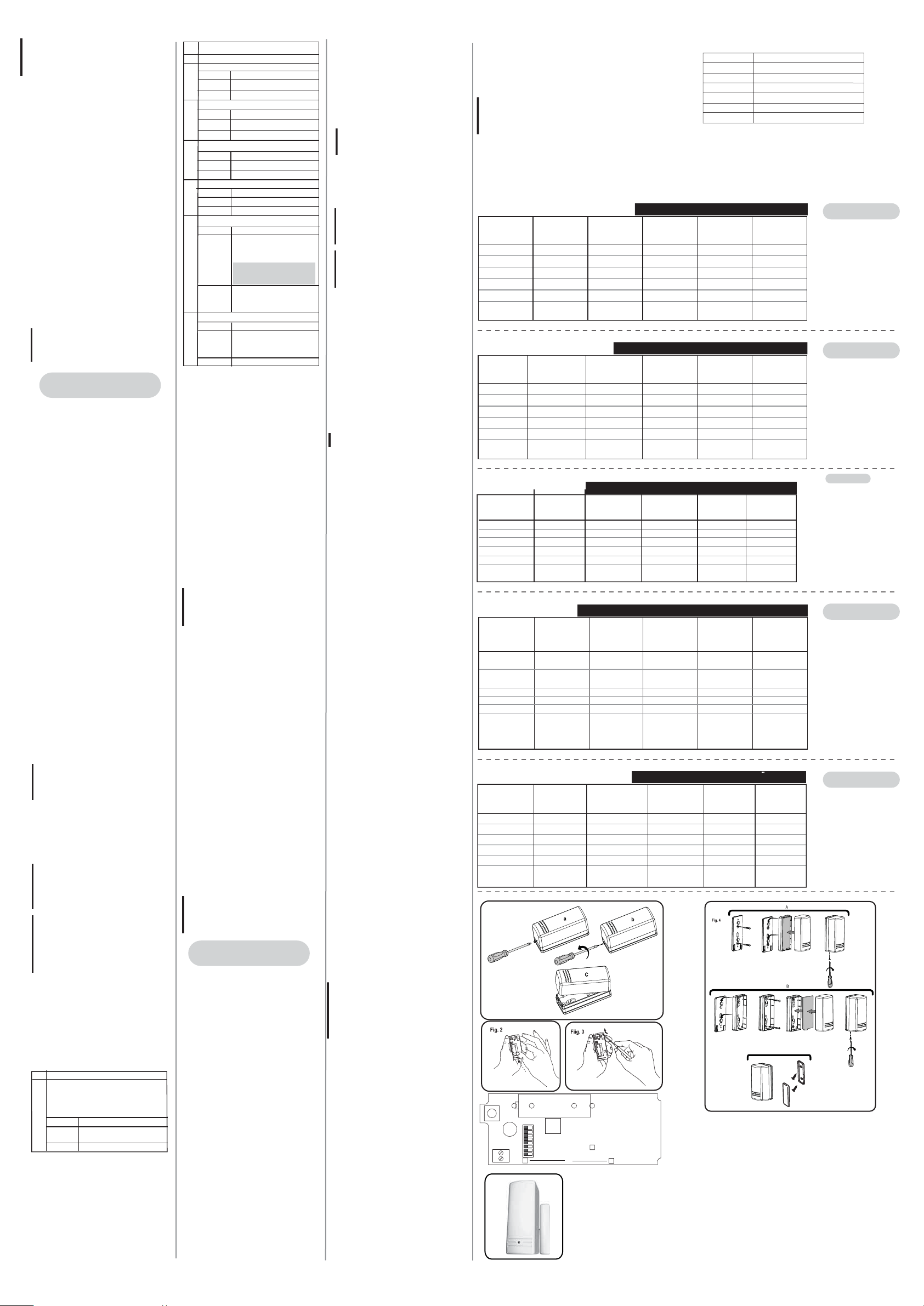
DIPSWITCH SETTING PER
OFF
AND
(4)
APPLICATION
N.C. INPUT
(T.B)
HOLD ON
ON: SLOW
ON: N.C.
ON
T.B USED
T.B
ONLY
APPLICATION
/ITEM
DIPSWITCH 7 (1)
DIPSWITCH6 (2)
DIPSWITCH 5
DIPSWITCH 4
T.B
LOGIC
(MAGNET &T.B)
MAGNET
ONLY
HOLD ON
ON: SLOW
OFF: N.O.
OFF
FREE
MAGNET
ONLY
MAGNET+N.C.
INPUT (T.B)
HOLD ON
ON: SLOW
ON: N.C.
OFF
T.B USED
AND
(3)
MAGNET+N.O.
INPUT (T.B)
HOLD ON
ON: SLOW
OFF: N.O.
T.B USED
JUMPER INSTALLATION POUR CAHQUE APPLICATION
APPLICATION
DIPSWITCH6 (2)
DIPSWITCH 5
DIPSWITCH 4
T.B
LOGIC
(EMANT & T.B)
APLICACIÓN /
DIP
DIP 7 (1) ON (REPOSO) ON (REPOSO)ON (REPOSO)
DIP 6 (2) ON (LENTO) ON (LENTO) ON (LENTO) ON (LENTO) ON (LENTO)
DIP 5 OFF (N.A.) ON (N.C.)
DIP 4
T.B
LÓGICA
INSTALLAZIONE RAPIDA:
APPLICAZ.
/ ITEM
Microinterruttore 7
(NOTA 1)
Microinterruttore 6
(NOTA 2)
Microinterruttore 5
Microinterruttore 4
T.B
LOGICA CONTATTO
INTERNO &
INGRESSO
ESTERNO T .B
EMANT
SEULEMENT
IN (HOLD-ON)
LENTEMENT
NO.
OUVERT-(EXTERIEUR)
LIBREMENT
EMANT
SEULEMENT
SÓLO CONTACTO
MAGNÉTICO
OFF
LIBRE T.B UTILIZADA
SÓLO
MAGNÉTICO
OUVERT-(EXTERIEUR)
UTILISATION T.B
CONFIG. MICROINTERRUPTORES EN FUNCIÓN DE LA APLICACIÓN
ENTRADA N.C. (T.B)
CONFIG. MICROINTERRUTTORI IN FUNZIONE DELL’APPLICAZIONE
SOLO CONTATTO
MAGNETICO
INTERNO
ON
(BLOCCO 2,5 MIN)
ON
(RISP. LENTA)
OFF (N. O.)
OFF (APERTO)
LIBERO
SOLO CONTATTO
MAGNETICO
INTERNO
ESTERNO N. C. (T.B)
(BLOCCO 2,5 MIN)
EMANT+N.C
INFORMATION
(T.B)
IN (HOLD-ON)
LENTEMENT
N.C.
ET
(3)
CONTACTO
MAGNÉTICO +
OFF
AND (Y)
(3)
CONTATTO
MAGNETICO
INT. + INGRESSO
ON
ON
(RISP. LENTA)
ON (N. C.)
OFF (APERTO)
T.B USATO
LOGICA AND
(NOTA 3)
EMANT+NO.
INFORMATION
(T.B)
IN (HOLD-ON)
LENTEMENT
N.C.
OUVERT-(EXTERIEUR)
UTILISATION T.B
ET
(4)
CONTACTO
MAGNÉTICO +
ENTRADA N.A. (T.B)
OFF (N.A.) ON (N.C.)
OFF
T.B UTILIZADA T.B UTILIZADA T.B UTILIZADA
AND (Y)
(4)
CONTATTO
MAGNETICO INT. +
INGRESSO
ESTERNO N. O. (T.B)
ON
(BLOCCO 2,5 MIN)
ON
(RISP. LENTA)
OFF (N. O.)
OFF (APERTO)
T.B USATO
LOGICA AND
(NOTA 4)
N.C.
INFORMATION
(T.B)
IN (HOLD-ON)
LENTEMENT
NO.
FERME- (INTERIEUR)
Utilisation T.B
T.B
SEULEMENT
ENTRADA N.C.
(T.B)
ON ON
SÓLO T.B SÓLO T.B
INGRESSO
ESTERNO N. C.
(T.B)
ON
(BLOCCO 2,5 MIN)
ON
(RISP. LENTA)
ON (N. C.)
ON (CHIUSO)
T.B USATO
SOLO
INGRESSO
ESTERNO T .B
FERME- (INTERIEUR)
ENTRADA N.A.
ON (REPOSO)ON (REPOSO)
Con¿guração dos Dipswitches
APLICAÇÃO
/ITEM
DIPSWITCH 7 (1)
DIPSWITCH 6 (2)
DIPSWITCH 5
DIPSWITCH 4
T.B
LOGICA
(Magnético & T.B)
Fig. 1
SW1
+
LD1
DIPSWITCH
T.B
2
1
Fig. 5
SOMENTE
MAGNETICO
ON (Tempo Morto)
ON (Lento)
OFF (N.A)
OFF (Habilitado)
LIVRE
SOMENTE
MAGNETICO
BATTERY
ON
1
SW2
2
3
4
5
678
S1
MAGNETICO +
ENTRADA N.F
(T.B)
ON (Tempo Morto)
ON (Lento)
ON (N.F)
OFF (Habilitado)
T.B USADO
“E”
(3)
-
ANTENNA
MAGNETO +
ENTRADA N. A.
(T.B)
ON (Tempo Morto)
ON (Lento)
OFF (N.A)
OFF (Habilitado)
T.B USADO
“E”
(4)
SPECIFICATIONS
ELECTRICAL
1PCT72X00000E
Battery Type: CR123 3V Lithium Battery
Current Consumption: 6
Frequency: RWT72: 868.65 MHz
RWT71: 433.92 MHz
Dead Time (HOLD ON): 2.5 minutes
Supervision Transmission: Every 15/65 minutes
Modulation Type: ASK
Battery Life: 5 years (HOLD ON)
PHYSICAL
Size: 81 x 35 x 32 mm (3.2 x 1.37 x 1.27 in.)
ENVIRONMENTAL
RF immunity: According to EN50130-4
Operating temperature: 0°C to 55° C (32° F to 131° F)
Storage temperature: -20°C to 60° C (-4° F to 140° F)
Speci¿cations are subject to change without prior notice.
Should any questions arise please contact your supplier.
ENTRADA N. F.
(T.B)
ON Tempo Morto)
ON (Lento)
ON (N.F)
ON (Desabilitado)
T.B USADO
APENAS
T.B
Description
Universal transmitter 868.65 MHz
Universal transmitter with magnet 868.65 MHz
Universal transmitter 433.92 MHz
Universal transmitter with magnet 433.92 MHz
Universal transmitter 433.92 MHz
Universal transmitter with magnet 433.92 MHz
ENGLISH
N.O. INPUT
(T.B)
HOLD ON
ON: SLOW
OFF: N.O.
ON
T.B USED
T.B
ONLY
1. HOLDON means 2.5 minutes dead
time, in HOLDOFF there is no dead
time.
2. In case of using fast respond shock
sensor, choose FAST (Dipswitch 6).
3. Only if the magnet is closed and the
external input (T.B) is closed the unit
will send restore. Otherwise the unit
is in open (alarm) state.
4. Only if the magnet is closed and the
external input (T.B) is open the unit
will send restore. Otherwise the unit
is in open (alarm) state.
FRANÇAIS
NO.
Information
(T.B)
IN (HOLD-ON)
LENTEMENT
NO.
Utilisation T.B
T.B
SEULEMENT
(T.B)
OFF (N.A.)
1. « Maintenu » (= HOLD ON) signi¿e
2min.30 de temps mort, par
opposition à HOLD OFF où il n'y a
pas de temps mort.
2. Si vous utilisez un détecteur de
chocs à réaction rapide,
sélectionnez l'option « rapide »
(FAST) (Dipswitch 6).
Ce n'est que si l'aimant est fermé
3.
et que l'entrée externe (T.B) est
fermée que l'appareil enverra un
message de remise en service.
Sinon, il reste en position (d'alarme).
Ce n'est que si l'aimant est fermé
4.
et que l'entrée externe (T.B) est
ouverte que l'appareil enverra un
message de remise en service.
Sinon, il reste en position (d'alarme).
ESPAÑOL
1. REPOSO signi¿ca 2,5 minutos de
tiempo muerto entre ransmisiones
de alarma para ahorrar batería.
En la posición OFF no hay
tiempos muertos.
2. En caso de utilizar detectores
inerciales de respuesta rápida,
poner el DIP 6 en posición OFF
(RÁPIDO).
3. La unidad mandará la señal de
restauración sólo si el magnético
está cerrado y la entrada externa
(T.B) está cerrada. De lo
contrario la unidad está abierta
(Alarma).
4. La unidad mandará la señal de
restauración sólo si el magnético
está cerrado y la entrada externa
(T.B) está abierta. De lo contrario la
unidad está abierta (Alarma).
ITALIANO
INGRESSO
ESTERNO N. O.
(T.B)
ON
(BLOCCO 2,5 MIN)
ON
(RISP. LENTA)
OFF (N. O.)
ON (CHIUSO)
T.B USATO
SOLO INGRESSO
ESTERNO T .B
1. La funzione BLOCCO 2,5 m. abilita
un tempo di blocco trasmissioni di
2.5 minuti dopo una segnalazione
(e relativo ripristino), con il relativo
microinterruttore in OFF, il blocco
trasmissioni non è attivo per cui il
trasmettitore trasmette sempre ogni
variazione di stato.
2. Per usare una risposta veloce del
circuito per i rivelatori inerziali,
selezionare RISPOSTA VELOCE
posizionando il microinterruttore 6
in OFF.
3. Solo se il contatto magnetico interno
è chiuso e l’ingresso esterno (T.B)
è chiuso l’unità trasmette il segnale
di ripristino. In caso contrario l’unità
è in stato “aperto” (allarme).
4. Solo se il contatto magnetico interno
è chiuso e l’ingresso esterno (T.B)
è aperto l’unità trasmette il segnale
di ripristino. In caso contrario l’unità
è in stato “aperto” (allarme).
PORTUGUÊS
ENTRADA N. A.
(T.B)
ON (Tempo Morto)
ON (Lento)
OFF (N.A)
ON (Desabilitado)
T.B USADO
APENAS
T.B
C
μA standby
1. HOLD ON signi¿ca 2.5 minutos de
intervalo, de "tempo m orto". Em
Hold OFF não existe intervalo.
2. Caso seja utilizada uma resposta
rápida para detectores de impacto
ative o (Dipswitch 6) FAST.
3. Apenas se o contato magnético e a
en trada externa (T.B) estiverem
fechadas a unidade enviará o
sinal de restauração.
4. Apenas se o contato magnético estiver
fechado, e a entrada (T.B) estiver
aberta, a unidade enviará um sinal de
restauração. Se não a unidade continuará
em alarme.
 Loading...