

Rinnai RHFE-556FA, RHFE-556FTRA Owner's Operation And Installation Manual
~'l
...
·.
''il1
HOME OWNER I INSTALLER
FOR YOUR SAFETY
THIS MANUAL MUST BE READ IN ITS
ENTIRETY BEFORE OPERATING HEATER
RHFE-556FAlFTRA
ENERGYSAVER
GAS DIRECT VENT WALL FURNACE
Owner's Operation and Installation Manual
WARNING: IF THE INFORMATION IN THIS MANUAL IS NOT FOLLOWED
EXACTLY, A FIRE OR EXPLOSION MAY RESULT CAUSING PROPERTY
DAMAGE, PERSONAL INJURY OR LOSS
OF
LIFE.
DO NOT STORE OR USE GASOLINE OR OTHER FLAMMABLE VAPORS
AND LIQUIDS
IN
THE VICINITYOFTHIS OR ANY OTHER APPLIANCE.
WHAT TO DO IF YOU SMELL GAS
• DO NOTTRY
TO
LIGHT ANY APPLIANCE.
• DO NOT TOUCH ANY ELECTRICAL SWITCH; DO NOT USE ANY PHONE
IN YOUR BUILDING.
• IMMEDIATELY CALL YOUR GAS SUPPLIER FROM A NEIGHBOR'S
PHONE. 'FOLLOW THE GAS
SUPPI:IER'S INSTRUCTIONS.
•
. IF YOU CANNOT REACH YOUR GAS SUPPLIER, CALL THE FIRE
DEPARTMENT.
INSTALLATION AND SERVICE MUST BE PERFORMED BY A QUALIFIED
INSTALLER, SERVICE AGENCY OR THE GAS SUPPLIER.
INSTALLER: MUST LEAVE MANUAL WITH UNIT AFTER INSTALLATION.
OWNER: RETAIN THIS MANUAL SAFELY,
FOR FUTURE REFERENCE.

WARNING
IMPROPER INSTALLATION, ADJUSTMENT, ALTERATION,
SERVICE
OR
MAINTENANCE
CAN CAUSE PROPERTY
DAMAGE,
PERSONAL
INJURY
OR
LOSS
OF
LIFE.
REFER
TO
THE
OWNER'S
INFORMATION
MANUAL
PROVIDED WITH THIS APPLIANCE. INSTALLATION AND
SERVICE
MUST
BE
PERFORMED
BY
A
QUALIFIED
INSTALLER, SERVICE AGENCY OR THE GAS SUPPLIER.
Rinnai Gas FF Heater
(Forced Flue)
ENERGYSAVER RHFE-556FAlFTRA
Table
of
Contents
Page
FEATURES OF THE RHFE-556 UNITS/SAFETY DEVICES 1
TECHNICAL DATA/GAS PRESSURE
SETIING
2
IMPORTANT POINTS/USAGE AND INSTALLATION MUST 3
DIMENSIONS 5
SPECIFICATIONS 6
SAFETY POINTS 8
GETIING
TO KNOW YOUR NEW RHFE-556FA/FTRA 10
CONTROL PANEL LAYOUT ,
11
REMOTE CONTROL 12
CUT-AWAY DIAGRAM 13
NOTICE BEFORE INSTALLATION 14
INSTALLATION INSTRUCTIONS
':
15
GAS CONNECTION 16
VENT LOCATION 17
FITIING
TOP SPACE+WALL CLIP 17
USA/CANADIAN VENT REGULATIONS 18
LOCATION/CLEARANCES 19
SLEEVE AND MANIFOLD INSTALLATION
21
OPERATING INSTRUCTION LABEL 25
ADDITIONAL CUSTOMER OPERATING INFORMATION 26
PROGRAMMING ON/OFF TIMERS/CLOCK(556FTRA ONLY) 32
OVERRIDE FUNCTION/USING THE REMOTE CONTROL(556FTRA ONLY) 36
TESTING/CHECK 37
PRE-SERVICE CHECK 38
TROUBLE SHOOTING 39
ERROR MESSAGES 40
MAINTENANCE/SERViCE
41
WIRING DIAGRAM 42
WARRANTY INFORMATION .43
SCHEMATIC DIAGRAM/PARTS LIST .45
RHFE-556 FLOW DIAGRAM :
5.5
,EXTENDED FLUE PIPE KIT 57
CONVERSiON 62
J
J
rJFEATURES OF THE RHFE-556FAlFTRA UNITSI
(
\"
.:..-_----------------------------.
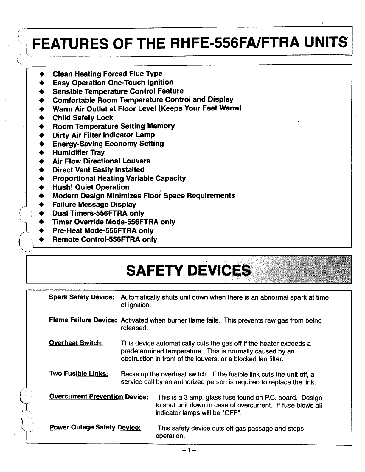
• Clean Heating Forced Flue Type
• Easy Operation One-Touch
Ignition
• Sensible Temperature
Control
Feature
• Comfortable Room Temperature
Control
and
Display
• Warm
Air
OutletatFloor
Level (Keeps Your Feet Warm)
•
Child
Safety
Lock
• Room Temperature Setting Memory
•
Dirty
Air
Filter
Indicator
Lamp
• Energy-Saving
Economy
Setting
•
Humidifier
Tray
•
Air
Flow Directional
Louvers
• Direct Vent Easily Installed
•
Proportional
Heating Variable Capacity
• Hush! Quiet Operation )
• Modern Design Minimizes
Floor
Space Requirements
(
• Failure Message Display
• Dual Timers-556FTRA
only
"-~
/ •
Timer
Override Mode-556FTRA
only
(\,,_,_:__
~_~e_~_~_~e_at_cM_o_~_~re_~_I~_~5_6
6_7-r_R_:_A_o_~_~_ly
__1
Spark
Safety Device: Automatically shuts unit down when there is an abnormal spark at time
of ignition.
Flame Failure Device: Activated when burner flame fails. This prevents raw gas from being
released.
Overheat Switch:
Two Fusible
Links:
This device automatically cuts the gas off if the heater exceeds a
predetermined temperature. This
is
normally caused by an
obstruction
in
front of the louvers, or a blocked fan filter.
Backs up the overheat switch. If the fusible link cuts the unit off, a
service call by an authorized person is required to replace the link.
Overcurrent
Prevention Device: This is a 3 amp. glass fuse found on p.e; board. Design
to shut unit down in case of overcurrent. Iffuse
bloWs
all
indicator lamps will be "OFF".
Power Outage Safety Device:
This safety device cuts off gas passage and stops
operation.
-1-
TECHNICAL
DATA
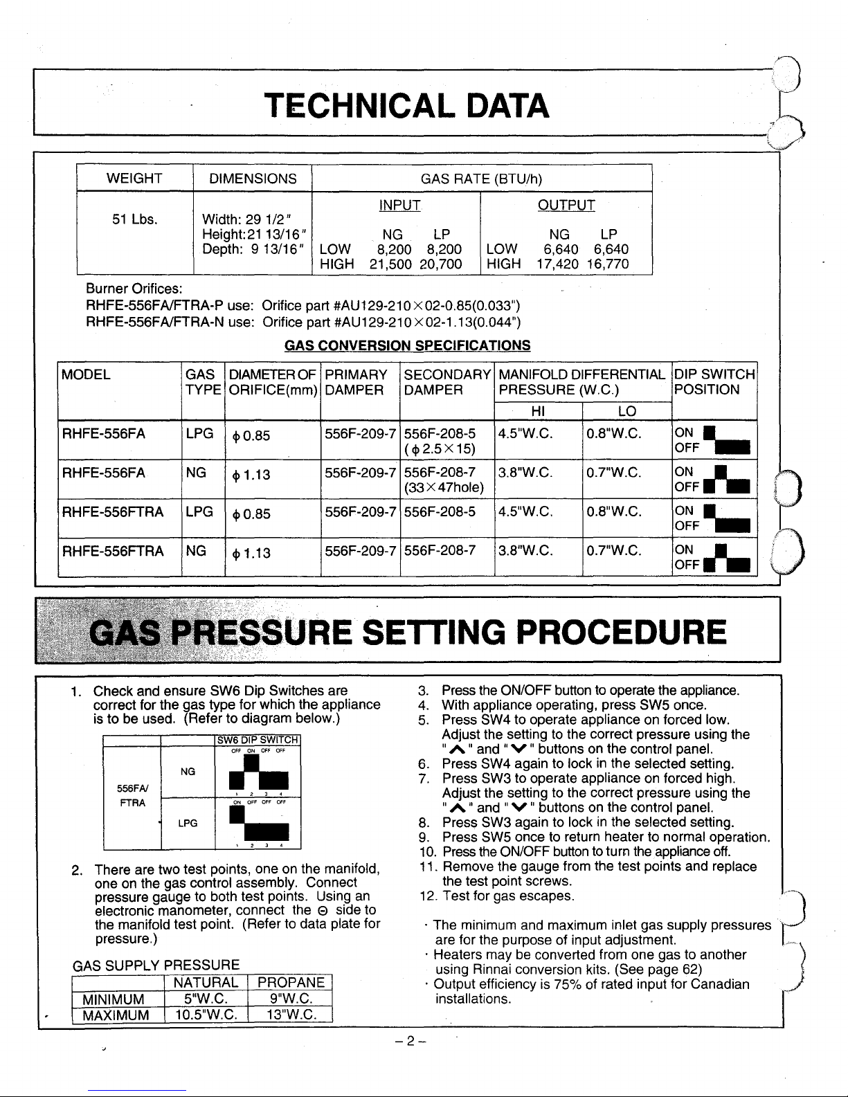
WEIGHT
DIMENSIONS GAS RATE (BTU/h)
INPUT OUTPUT
51
Lbs.
Width: 29 1/2"
Height:
21
13/16"
NG
LP
NG
LP
Depth: 9 13/16"
LOW
8,200
8,200
LOW
6,640
6,640
HIGH 21,500 20,700
HIGH 17,420 16,770
Burner Orifices:
RHFE-556FA/FTRA-P use: Orifice part #AU129-21 0
x 02-0.85(0.033")
RHFE-556FA/FTRA-N use: Orifice part #AU129-210
x02-1.13(0.044")
GAS CONVERSION SPECIFICATIONS
MODEL GAS
DIAMETER
OF
PRIMARY SECONDARY
MANIFOLD DIFFERENTIAL DIP SWITCH
TYPE ORIFICE(mm) DAMPER DAMPER
PRESSURE (W.C.) POSITION
HI
LO
RHFE-556FA LPG
<1>0.85
556F-209-7 556F-208-5
4.5"W.C. 0.8"W.C.
ON'"
(<I>
2.5 x 15)
OFF
RHFE-556FA
NG
<I>
1.13
556F-209-7
556F-208-7
3.8"W.C. 0.7"W.C.
ON
J'.
(33 x47hole)
OFF
RHFE-556FTRA LPG
<1>0.85
556F-209-7 556F-208-5
4.5"W.C. 0.8"W.C.
ON'"
OFF
RHFE-556FTRA
NG
<I>
1.13
556F-209-7
556F-208-7
3.8"W.C. 0.7"W.C.
ON
J'.
OFF
URE
SETTING PROCEDURE
1.
Check and ensure SW6 Dip Switches are
correct for the gas type for which the appliance
is
to be used. (Refer to diagram below.)
SW6 DIP SWITCH
2.
There are two test points, oneonthe manifold,
one
on
the gas control assembly. Connect
pressure gauge to both test points. Using
an
electronic manometer, connect the e side to
the manifold test point. (Refer to data plate for
pressure.)
GAS SUPPLY PRESSURE
1 2 J 4
3.
Press the ON/OFF button to operate the appliance.
4.
With appliance operating, press SW5 once.
5.
Press SW4 to operate applianceonforced low.
Adjust the setting to the correct pressure using the
"A " and
"V
" buttons
on
the control panel.
6.
Press SW4 again to lockinthe selected setting.
7.
Press SW3 to operate applianceonforced high.
Adjust the setting to the correct pressure using the
"A " and
"V
" buttons
on
the control panel.
8.
Press SW3 again to lockinthe selected setting.
9.
Press SW5 oncetoreturn heater to normal operation.
10.
Press
the
ON/OFF
buttontoturn the appliance
off.
11. Remove the gauge from the test points and replace
the test point screws.
12.
Test for gas escapes.
J'~~
· The minimum and maximum inlet gas supply pressures
·1··
.
are for the purpose of input adjustment.
r._·
J
'·.·.·
.
· Heaters maybeconverted from one gas to another
using Rinnai conversion kits. (See page
62)
· Output efficiency is 75% of rated input for Canadian
installations.9"W.C.
13"W.C.
PROPANE
~
I 2 J 4
NG
LPG
556FAI
FTRA
NATURAL
MAXIMUM 10.5"W.C.
MINIMUM 5"W.C.
-2-
~
.~
IMPORTANT
POINTSIUSAGE
AND
INSTALLATION
MUSTS-I
Unpack heater and check for damage. (DO NOT INSTALL DAMAGED HEATER.) If heater is
damaged, contact your supplier for advise. Before installing a heater, check the label for the correct gas
type (see label on side of heater). Referto local gas authority for confirmation of gas type if you are in
doubt.
Included in Carton:
. Customers Operating Information
. Conversion kits
IMPORTANT
Before using
this
product, please read
this
manual carefullytoinsure proper useofproduct.
1.
The appliance must be installedinaccordance with state and local codes.
2.
For information on gas type, see data plate on the appliance.
3.
This heater must not be installed whese curtains or other combustible materials could come into
contact with it.
In
some cases curtains may need restraining.
4.
This appliance is not designed to be built in.
5.
If you move, check the gas typeinthe area where you are moving to. The local gas authority will be
able to advise on local regulations.
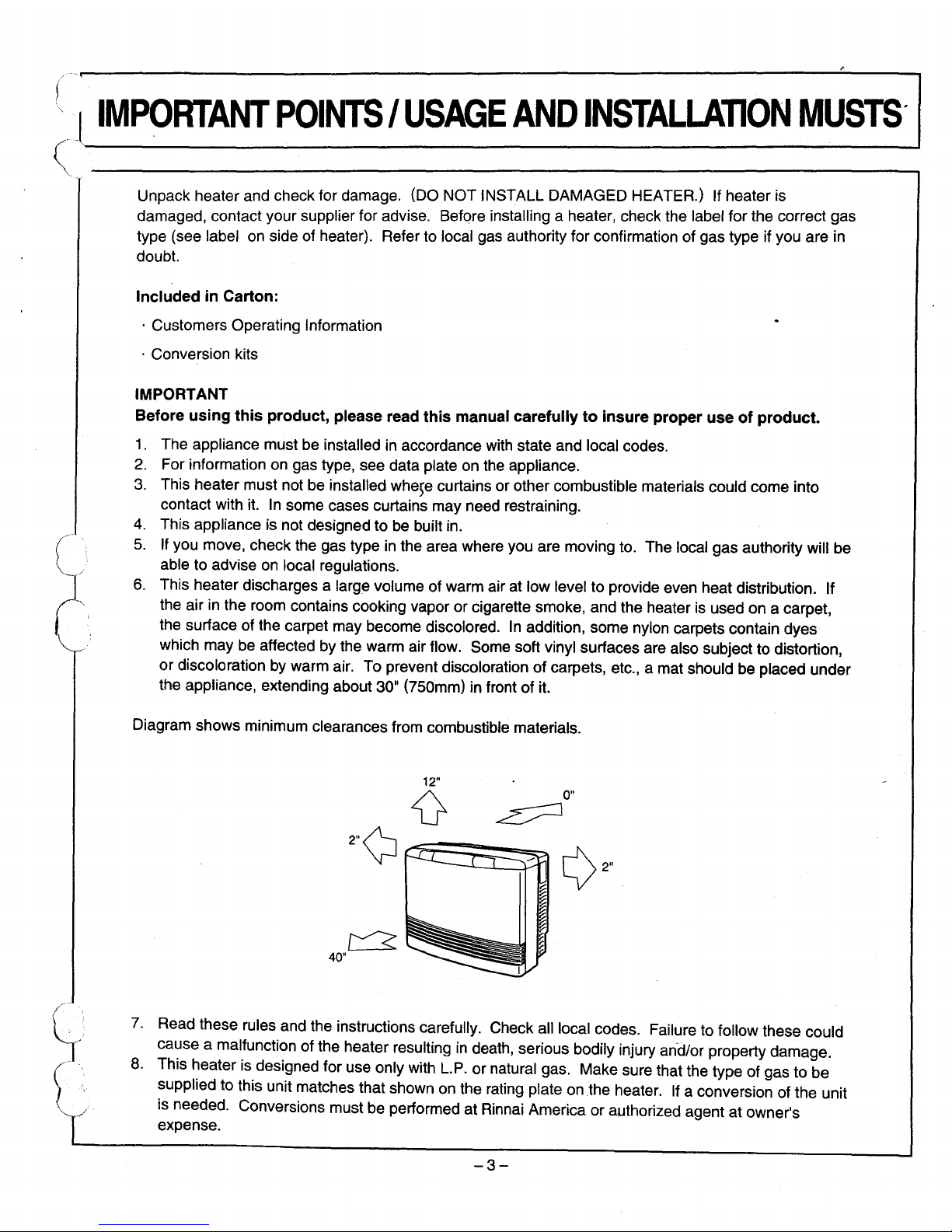
6.
This heater discharges a large volume of warm air at low level to provide even heat distribution. If
the air in the room contains cooking vapor or cigarette smoke, and the heater is used on a carpet,
the surface of the carpet may become discolored.
In
addition, some nylon carpets contain dyes
which may be affected by the warm air flow. Some soft vinyl surfaces are also subject to distortion,
or discoloration by warm air. To prevent discoloration
of
carpets, etc., a mat should be placed under
the appliance, extending about 30" (750mm) in front
of
it.
Diagram shows minimum clearances from combustible materials.
~
40"
12"
{}
0"
~
7.
Read these rules and the instructions carefully. Check all local codes. Failure to follow these could
cause a malfunction of the heater resulting
in
death, serious bodily injury and/or property damage.
8.
This heater is designed for use only with L.P. or natural gas. Make sure that the type of gas to be
supplied to this unit matches that shown on the rating plate on the heater. If a conversion of the unit
is needed. Conversions must be performed at Rinnai America or authorized agent
at
owner's
expense.
-3-
9.
WARNING: Any change to this heater or its controls canbedangerous.
10. If a gas leak is suspected,
turf} heater off, turn gas supply valve off at appliance connector valve.
Open windows to ventilate area immediately and contact your dealer or gas company.
11
.00
not place clothing or flammable materials, gasoline and other flammable vapors and liquids, on or
near the heater.
12. Young children should be carefully supervised when they are
in
the same room with the heater.
13. LPG containers must not
be
installed indoors.
14. Do not use this room heater if any part has been under water. Immediately cal! a qualified service
technician to inspectthe room heater and to replace any part of the control system and any gas
control which has been under water.
15. Adequate clearances for accessibility for purposes of servicing and proper operation should
be
provided.
16. Adequate clearances around air openings should be provided.
17. Do not install
in
areas where curtains, drapes, clothing, or other moving flammables are within 12
inches of this unit.
18. Periodic examination of the venting system is required.
19. The flow of combustion and ventilation air should not be obstructed.
20. "This appliance must
be
installed in accordance with the manufacturer's instructions and the
Manufactured Home Construction and Safety Standard, Title 24 CFR, Part 3280, or a standard for
manufactured home ANSI A 22512/NFPA
501
A"
21. "This appliance must be installedinaccordance with the current standard CSA Z240.4 GAS
EQUIPPED RECREATIONAL VEHICLES AND MOBILE HOUSING. Cet appareil doit ette installe
conformement aux, exigences de la norme Z240.4 en vigeuer de I'ACNOR, Installations de gaz dans
les constructions mobiles et vehicules recreatifs."
GENERAL INFORMATION
THIS SERIESISDESIGN CERTIFIEDBY THE AMERICAN GAS
ASSOCIATION LABORATORIES (AGA) AND INTERNATIONAL
APPROVAL SERVICES (lAS).
ALTERATION OF THE ORIGINAL DESIGN INSTALLED OTHER
THAN AS SHOWN
IN
THESE INSTRUCTIONS OR USED WITH
A TYPE OF GAS NOT SHOWN
ON
THE RATING PLATE, IS
THE
RESPONSIBILITY
OF THE PERSON AND COMPANY
MARKING THE CHANGE.
· Rinnai is continually updating and improving products. Therefore, specifications are subject to
change without notice.
· Thank
you=for
purchasing Rinnai force flue gas heater.
· Please read the warranty thoroughly and keep it
in
a safe place.
-4-
(;~~
•..
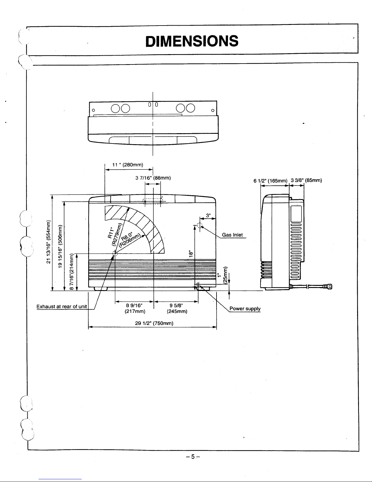
D-IM-E-N-S-IO-N-S-----........;.....·I
00
o 0
00
01
0
I
'---
(
I r
'1
.-
iJT€)
=
=
=
=
=
=
=
=
=
=
=
=
=
=
=
=
o
61/2"
(165mm)
33/8"
(85mm)
Power supply
Gas Inlet
9 5/8"
(245mm)
89/16"
(217mm)
11
"(280mm)
•
-I
3 7/16" (88mm)
E
E
E
v
E
III
!£.
(0
0
<0
!£.
....
<0
M
....
....
LO
E
N
....
E
OJ
v
....
....
~
<0
....
r:::
co
Exhaust at rear of unit
(
(
291/2"
(750mm)
-5,..-
'I
SP_
.•.
,E_C_F--.:-.,C_A_
..
~_IO_·.·
N_S---.:-
~(g
BTU/h
MIN. CLEARANCES
I
FAN
CFM
I
i
MODEL #
OUTPUT
INPUT
OUTPUT SIDE
TOP
FRONT
!
RH
FE-556FAlFTRA
Low
Low
LO:110.5
8,200
6,640
2"
12"
40"
High
(50mm)
(300mm)
(1
m)
NATURAL
High
HI:162.7
21,500
17,420
RHFE-556FAlFTRA
Low Low
LO:110.5
8,200
6,640
2"
12"
40"
High High
(50mm)
(300mm)
(1m)
PROPANE
20,700 16,770
HI:162.7
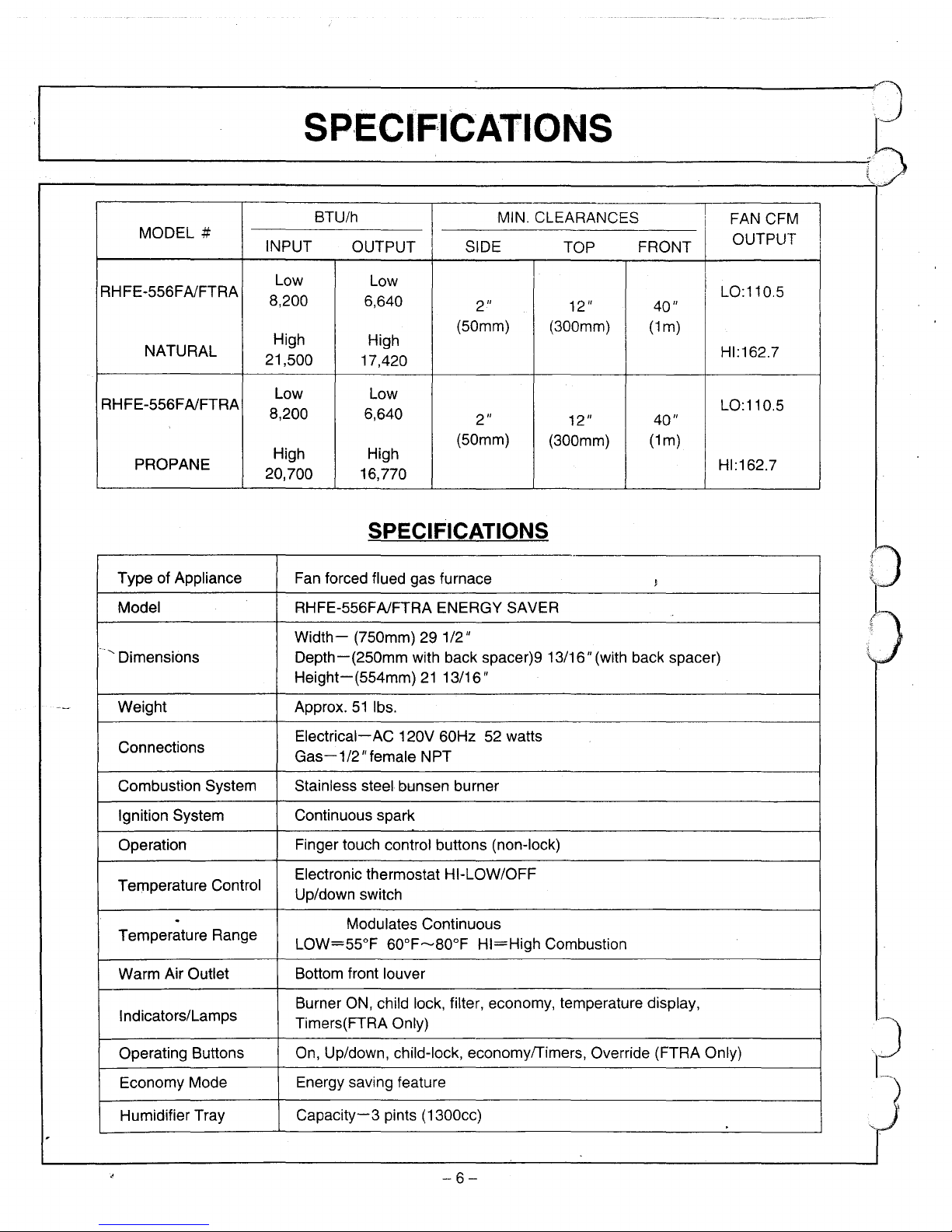
SPECIFICATIONS
Type of Appliance
Fan forced flued gas furnace
J
Model
RHFE-556FAlFTRA ENERGY SAVER
Width-
(750mm) 29 1/2"
'."
Dimensions
Depth-(250mm
with back spacer)9 13/16" (with back spacer)
Height-(554mm)2113/16"
Weight Approx.
51
Ibs.
Connections
Electrical-AC
120V 60Hz 52 watts
Gas-1/2/1female NPT
Combustion System Stainless steel bunsen burner
Ignition System
Continuous spark
Operation Finger touch control buttons (non-lock)
Temperature Control
Electronic thermostat HI-LOW/OFF
Up/down switch
.
Modulates Continuous
Temperature Range
LOW=55°F
60°F-80°F
HI=High
Combustion
Warm Air Outlet
Bottom front louver
Indicators/Lamps
Burner ON, child lock, filter, economy, temperature display,
Timers(FTRA Only)
Operating Buttons
On, Up/down, child-lock, economy/Timers, Override (FTRA Only)
Economy Mode
Energy saving feature
Humidifier Tray
Capacity-3
pints (1300cc)
,J
1.--
-6-
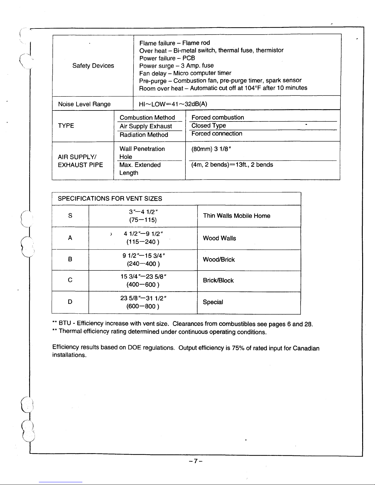
Flame failure - Flame rod
Over heat - Bi-metal switch, thermal fuse, thermistor
Power failure - PCB
Safety Devices Power surge - 3 Amp. fuse
Fan delay - Micro computer timer
Pre-purge - Combustion fan, pre-purge timer, spark sensor
Room over heat - Automatic cut off at 104°F after 10 minutes
Noise Level Range
HI-LOW=41-32dB(A}
Combustion Method
Forced combustion
TYPE
Air Supply Exhaust
Closed Type
.
Radiation Method
Forced connection
Wall Penetration
(80mm) 3
1/8"
AIR SUPPLY/
Hole
EXHAUST PIPE
Max. Extended
(4m,
2 bends}=13ft., 2 bends
Length
SPECIFICATIONS FOR VENT SIZES
S
3"-41/2"
Thin Walls Mobile Home
(75-115)
A
>
4
1/2"~9
1/2"
Wood Walls
(115-240
)
B
91/2"-153/4"
Wood/Brick
(240-400
)
C
15 3/4
"-23
5/8"
Brick/Block
(400-600
)
D
235/8"-31
1/2"
Special
(600-800
)
** BTU - Efficiency increase with vent size. Clearances from combustibles see pages 6 and 28.
** Thermal efficiency rating determined under continuous operating conditions.
Efficiency results based
on
DOE regulations. Output efficiency is 75% of rated input for Canadian
installations.
-7-
SAFETY·POINTS
i/l
l)
'------------'---------1f~)
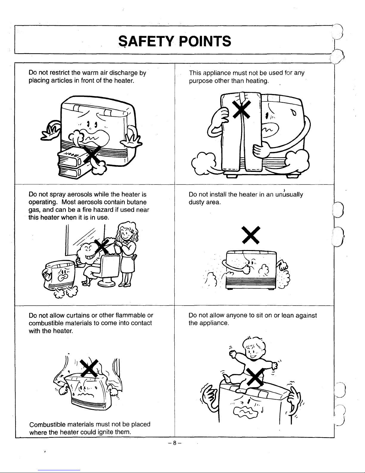
Do not restrict the warm airdischarge by
placing articles
in
front of the heater.
Do not spray aerosols while the heater is
operating. Most aerosols contain butane
gas, and can be a fire hazard if used
near
this heater when it isinuse.
Do not allow curtains or other flammable or
combustible materials to come into contact
with the heater.
Combustible materials must not
be
placed
where the heatercould ignite them.
-8-
This appliance must not be used for any
purpose other than heating.
Do not install the heater
in
an un6sually
dusty area.
x
Do not
allOW
anyone to sit on or lean against
the appliance.
,J
/)
/J
~;_,
S_A_F_E_T_y_P_O_IN_T_S
-1
"
("
~l
c:
s
·····;·:
..
·1
[
..
--.'.\
"
;1
/
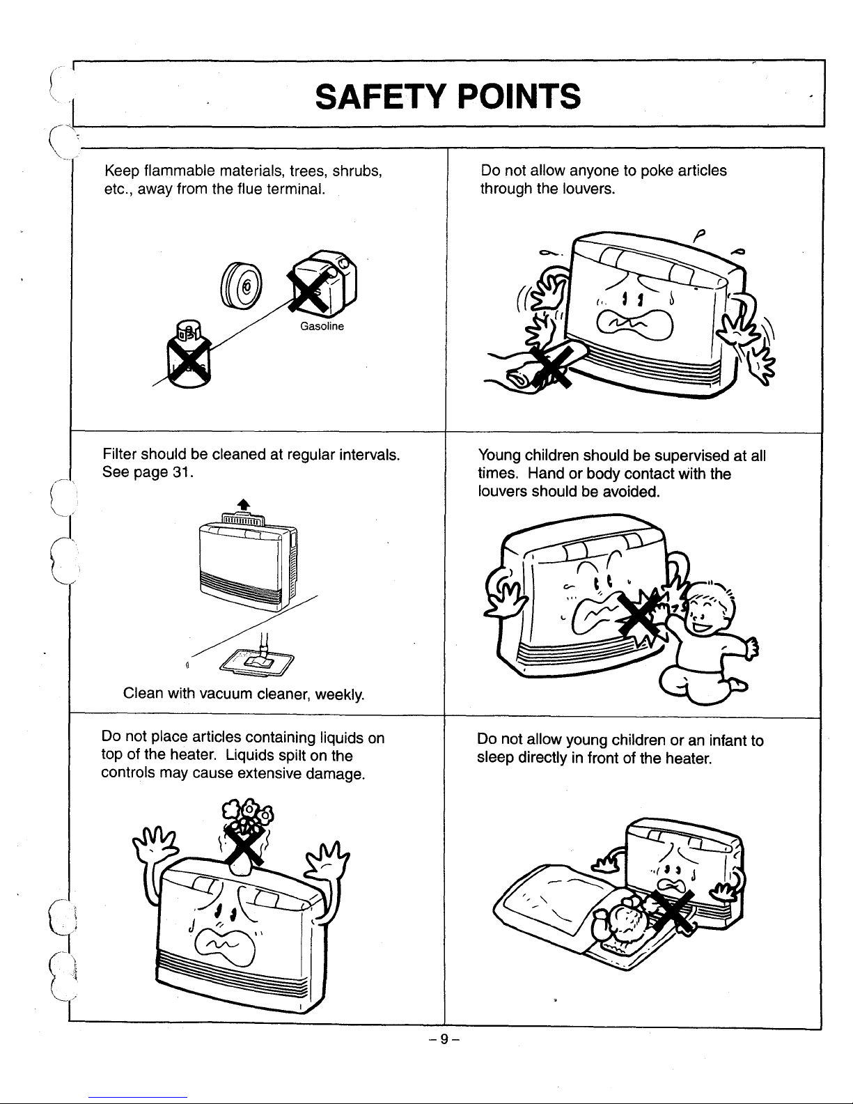
Keep flammable materials, trees, shrubs,
etc., away from the flue terminal.
Filter should be cleaned at regular intervals.
See page 31.
Clean with vacuum cleaner, weekly.
Do not place articles containing liquids on
top of the heater.
liquids
spilt on the
controls may cause extensive damage.
-9-
Do not allow anyone to poke articles
through the louvers.
Young children should be supervised at all
times. Hand
or
body contact with the
louvers should be avoided.
Do not allow young children
or
an infantto
sleep directly
in
front of the heater.
GETTING
TOKNO\lvYOUR
NEW RHFE-556 i
J
'-------------'------:;()
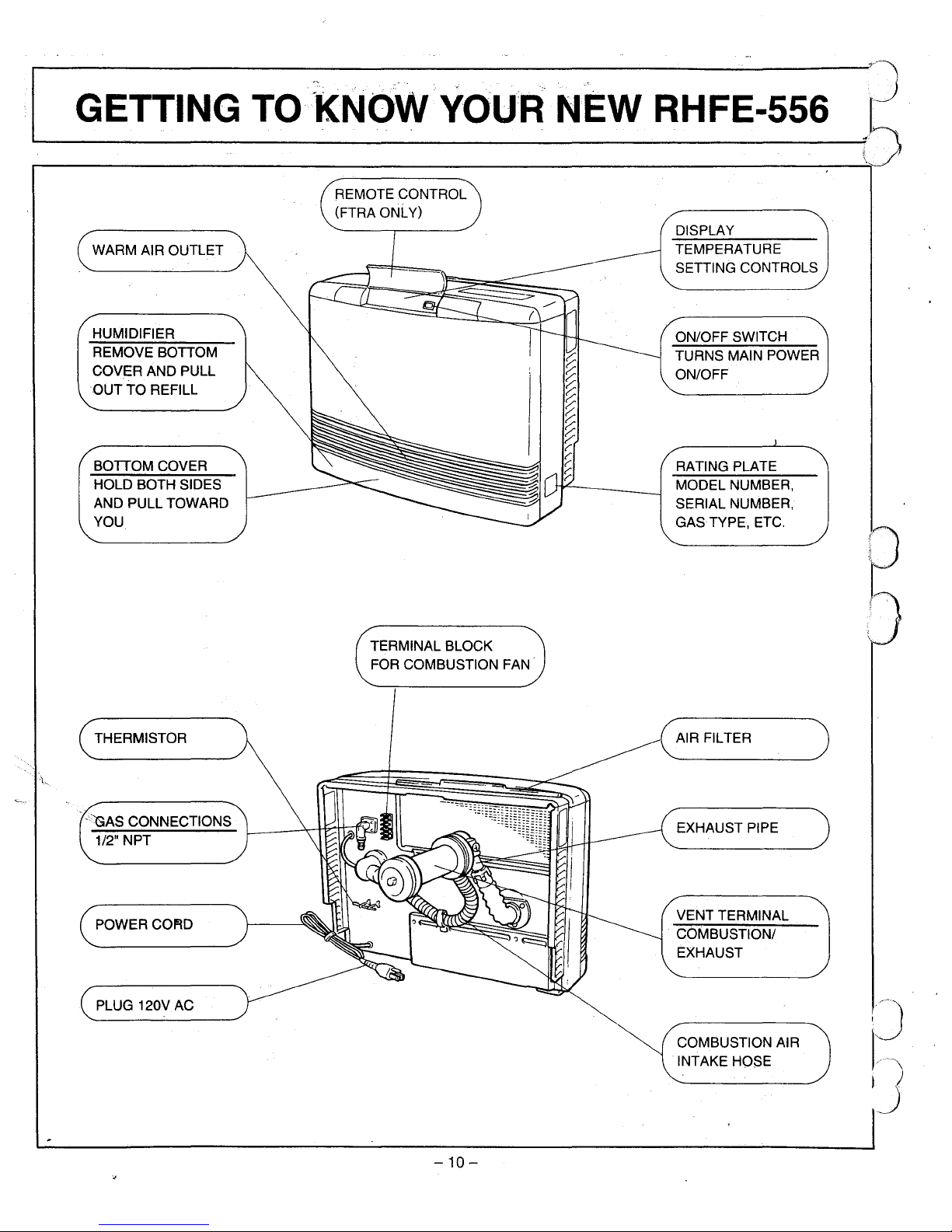
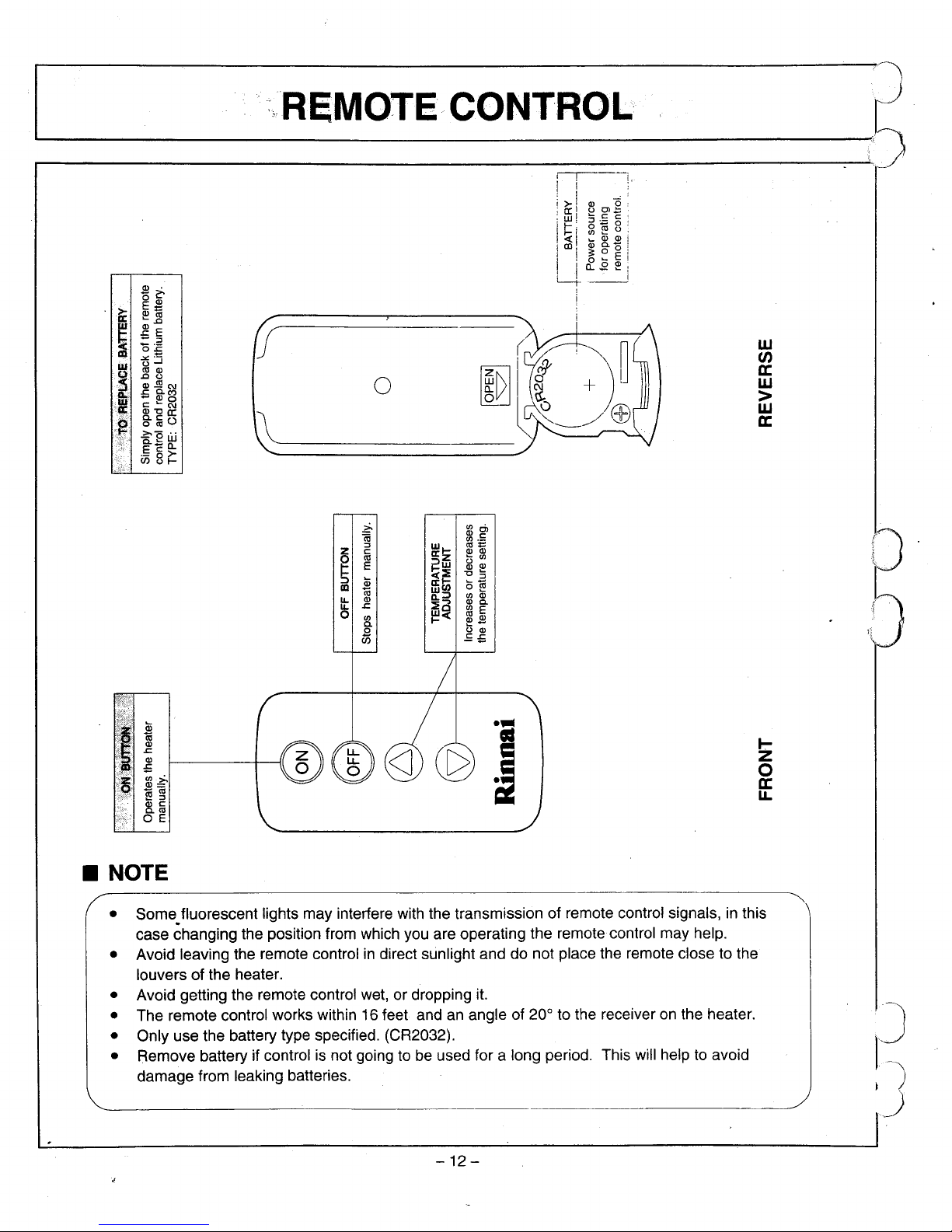
REMOTE CONTROL
(FTRA ONLY)
WARM AIR OUTLET
HUMIDIFIER
REMOVE BOTTOM
COVER AND PULL
OUT
TO REFILL
BOTTOM COVER
HOLD BOTH SIDES
AND PULL TOWARD
YOU
TERMINAL BLOCK
FOR COMBUSTION FAN'
DISPLAY
TEMPERATURE
SETTING CONTROLS
ON/OFF SWITCH
TURNS MAIN POWER
ON/OFF
RATING PLATE
MODEL NUMBER,
SERIAL NUMBER,
GASTYPE, ETC.
THERMISTOR
(AIR
FILTER
)
POWERCOfitD
PLUG 120V AC
-10
-
EXHAUST PIPE
VENT TERMINAL
COMBUSTION/
EXHAUST
COMBUSTION AIR
INTAKE HOSE
(1"...--..
C_O_N_T_RO_L_··
_PA_N_E_L_L_/4_~_O_U_T
'1
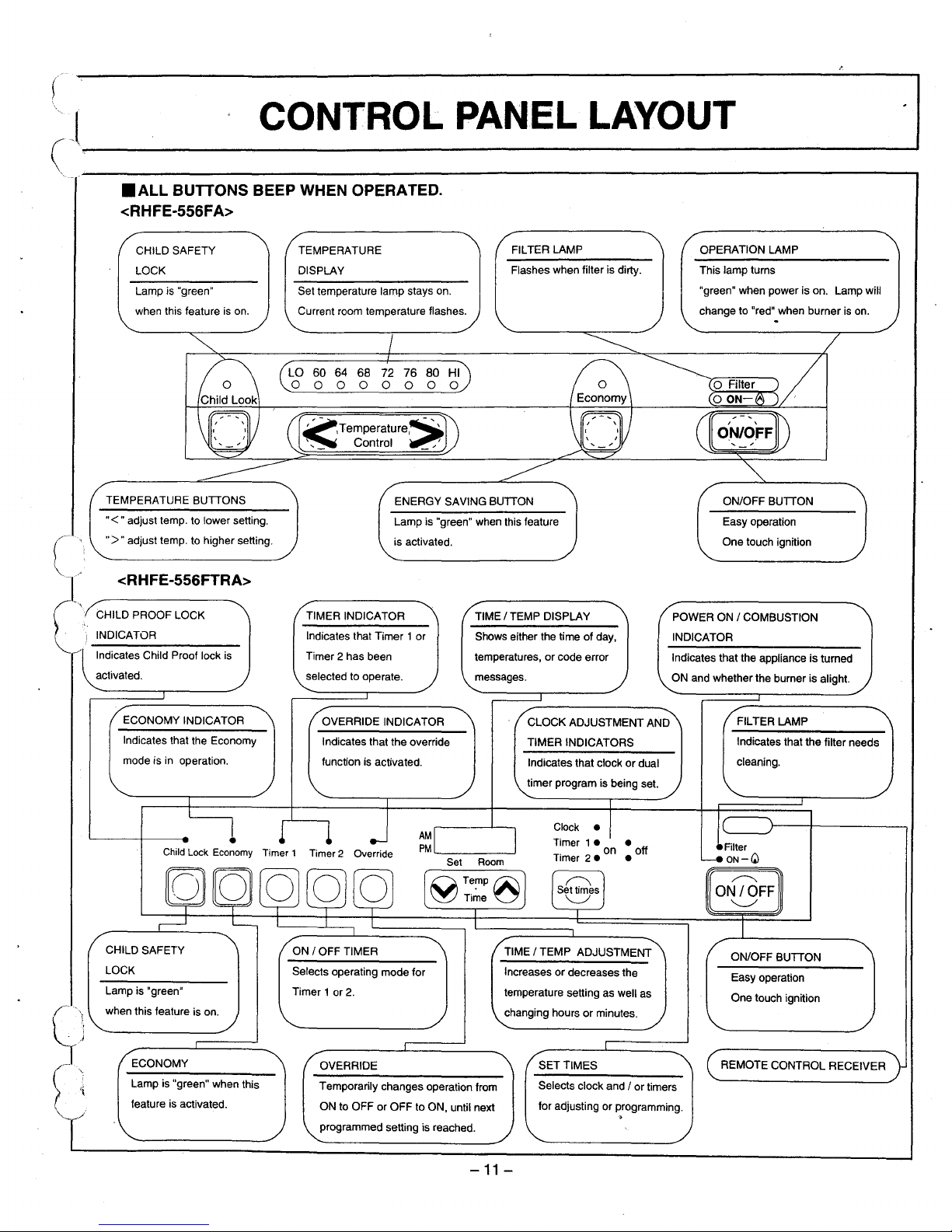
• ALL BUTTONS BEEP WHEN OPERATED.
<RHFE-556FA>
CHILD SAFETY
LOCK
Lamp is "green"
when this feature
is
on.
TEMPERATURE
DISPLAY
Set temperature lamp stays on.
Current room temperature flashes.
FILTER LAMP
Flashes when filter is dirty.
OPERATION LAMP
This lamp turns
"green" when power is on. Lamp will
change to "red" when burner
is
on.
60 64 68
000
ENERGY SAVING BUTTON
Lamp is "green" when this feature
is activated.
TEMPERATURE BUTTONS
"<"
adjust temp. to lower selling.
">
..
adjust temp. to higher selling.
<RHFE-556FTRA>
CHILD PROOF LOCK
INDICATOR
Indicates Child Proof lock is
activated.
TIMER INDICATOR
Indicates that Timer 1 or
Timer
2 has been
selected to operate.
TIME / TEMP DISPLAY
Shows either the time
of
day,
temperatures, or code error
messages.
ON/OFF BUTTON
Easy operation
One touch ignition
POWER ON / COMBUSTION
INDICATOR
Indicates that the appliance is turned
ON and whether the burner is alight.
Indicates that the filter needs
cleaning.
ON/OFF BUTTON
FILTER LAMP
Easy operation
One touch ignition
REMOTE CONTROL RECEIVER
Clock
•
Timer
1 •
on
• off
Timer
2.
•
Selects clock and / or timers
for adjusting or programming.
.
Indicates that clockordual
timer program is being set.
CLOCK ADJUSTMENT AND
TIMER INDICATORS
SET TIMES
TIME / TEMP ADJUSTMENT
Increases or decreases the
temperature selling as well as
changing hours
or
minutes.
AM
PM
'--
--'
OVERRIDE INDICATOR
Indicates that the override
function is activated.
Temporarily changes operation from
ON to OFF or OFF to ON, until next
programmed selting is reached.
OVERRIDE
Selects operating mode for
Timer
lor
2.
ON / OFF TIMER
•
Child
Lock
Economy
Timer 1 Timer 2 Override
ECONOMY
Lamp is "green" when this
feature is activated.
Indicates that the Economy
mode is
in
operation.
ECONOMY INDICATOR
Lamp is "green"
when this feature is on.
CHILD SAFETY
LOCK
-11-
""":,.REMOTE
CONTROL
"""~
[J
L..-.-
;")
o
w
en
a:
w
>
w
a:
~
U>
•
iii
~.~
Z
::>
WI-
cal:'
C
Ql Ql
§
ca
C:
z
~
U>
E
~~
~ ~
(j;
"::>
c:li;
~ -
lD
o
f1
iii
~;;
U>
Ql
LL
Ql
QlC-
LL
.r:
:::i:c
U>
E
0
U>
~<
~~
c-
o
U
Ql
CiS
E£
~
i
.r:
Ql
:5
~-~
-ca
f1
::>
Ql C
c-ca
OE
••
!
I-
Z
o
a:
LL
• NOTE
• Some.fluorescent lights may interfere with the transmission of remote control signals,inthis
case changing the position from which you are operating the remote control may help.
• Avoid leaving the remote control
in
direct sunlight and do not place the remote close to the
louvers of the heater.
• Avoid getting the remote control wet, or dropping it.
• The remote control works within 16 feet and
an
angle of 20° to the receiveronthe heater.
• Only use the battery type specified. (CR2032).
• Remove battery if control
is
not going to be used for a long period. This will help to avoid
damage from leaking batteries.
-12
-
~;"""'---"
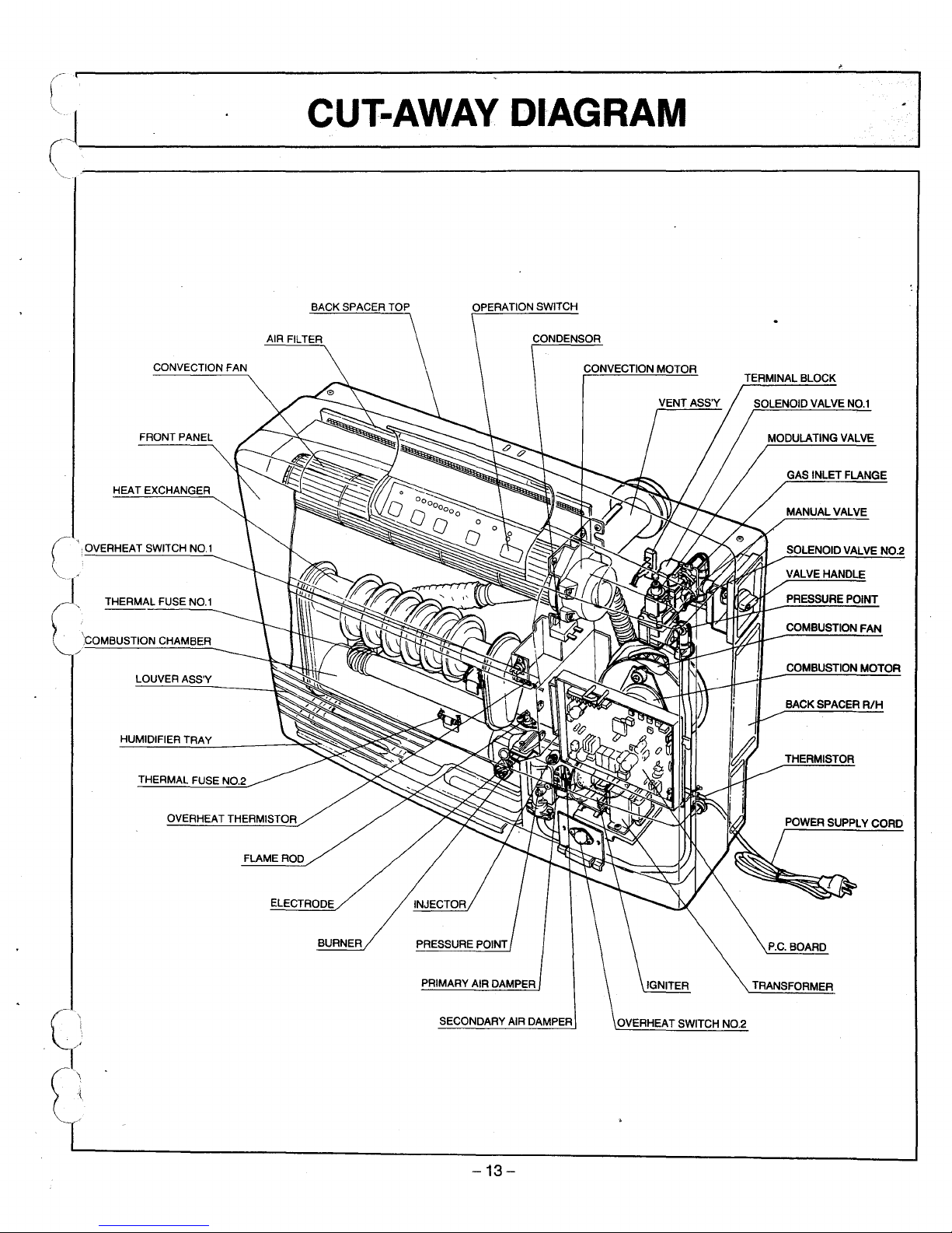
C_UT:_-_AW_,_AY_"
_D_IA_G_R_A_M
'/
\
~~-
FRONT
PANEL
LOUVER
ASS'Y
GAS
INLET FLANGE
COMBUSTION
MOTOR
COMBUSTION
FAN
PRESSURE
POINT
SOLENOID
VALVE
NO.2
VALVE
HANDLE
BACK
SPACER
R/H
THERMISTOR
P.C.BOARD
MODULATING
VALVE
TRANSFORMER
OVERHEAT
SWITCH
NO.2
CONVECTION MOTOR
SECONDARY
AIR
DAMPER
PRIMARY
AIR
DAMPER
ELECTRODE
BURNER
CONVECTION
FAN
OVERHEAT
THERMISTOR
FLAME
ROD
THERMAL
FUSE
NO.2
HUMIDIFIER
TRAY
HEAT
EXCHANGER
THERMAL
FUSE
NO.1
':COMBUSTION
CHAMBER
r\
OVERHEAT
SWITCHNO1
I
-13-
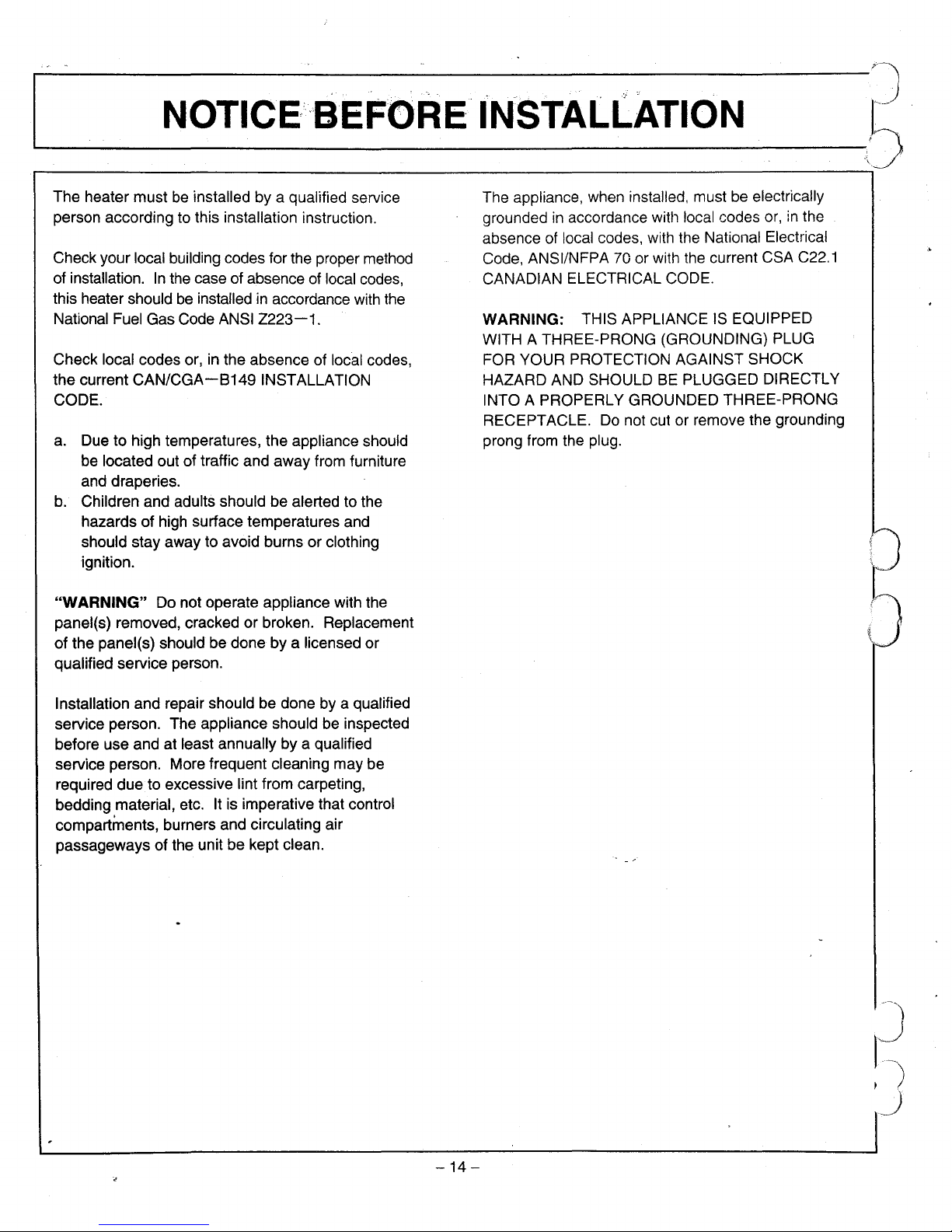
NOTICE/BEFORE INSTALL.ATION
;J
'------------\')
The heater mustbeinstalled by a qualified service
person according to this installation instruction.
Check your local building codes for the proper method
of installation.
In
the case of absence of local codes,
this heater should
be
installedinaccordance with the
National Fuel Gas Code ANSI
Z223-1.
Check local codes or,inthe absence of local codes,
the current
CAN/CGA-B149
INSTALLATION
CODE.
a.
Due to high temperatures, the appliance should
be located out of traffic and away from furniture
and draperies.
b.
Children and adults should be alerted to the
hazards of high surface temperatures and
should stay away to avoid burns or clothing
ignition.
"WARNING" Do not operate appliance with the
panel(s) removed, cracked or broken. Replacement
of the panel(s) should be done by a licensed or
qualified service person.
The appliance, when installed, must
be
electrically
grounded
in
accordance wittl local codes
or,inthe
absence of local codes, with the National Electrical
Code, ANSI/NFPA 70 or with the current CSA
C22.1
CANADIAN ELECTRICAL CODE.
WARNING: THIS APPLIANCE
IS
EQUIPPED
WITH A THREE-PRONG (GROUNDING) PLUG
FOR YOUR PROTECTION AGAINST SHOCK
HAZARD AND SHOULD
BE
PLUGGED DIRECTLY
INTO A PROPERLY GROUNDED THREE-PRONG
RECEPTACLE. Do not cut or remove the grounding
prong from the plug.
2
~(J
..
'
\".'
.
Installation and repair should be done by a qualified
service person. The appliance should be inspected
before use and at least annually by a qualified
service person. More frequent cleaning may be
required due to excessive lint from carpeting,
bedding material, etc. It is imperative that control
compartments, burners and circulating air
passageways of the unit be kept clean.
-14
-
~.~l,.-.
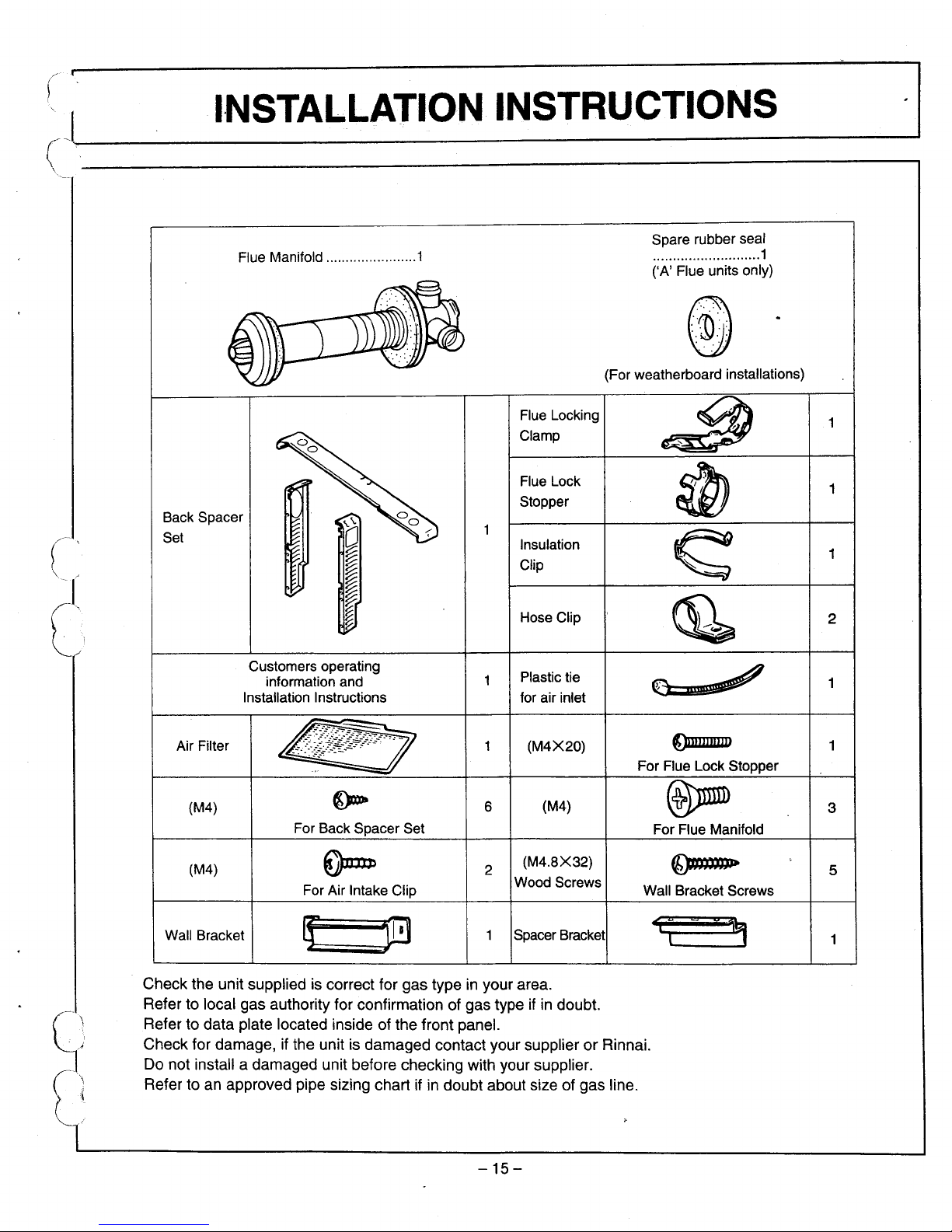
I.N_S_T:_A_LL_A_T_IO_N_.
_IN_S_T_R_U_C_TI_O_N_S
__
-----"
I
,
Flue Manifold 1
Spare rubber seal
...........................1
('A' Flue units only)
5
2
1
3
1
1
()nJlUIIIJIJ
For Flue Manifold
e=",,~
f/;)JtttJm
..
Wall Bracket Screws
For Flue Lock Stopper
(For weatherboard installations)
Flue Locking
Clamp
Flue Lock
Stopper
Insulation
Clip
Hose Clip
Plastic tie
for air inlet
(M4X20)
6
(M4)
2
(M4.8X32)
Wood Screws
(M4)
For Air Intake Clip
Air Filter
Customers operating
information and
Installation Instructions
(M4)
For Back Spacer Set
Back Spacer
Set
('
('
Wall Bracket Spacer Bracket
o
.?:t
(-
...• )
':1'
\
Check the unit supplied is correct for gas typeinyour area.
Refer to local gas authority for confirmation of gas type
ifindoubt.
Refer to data plate located inside of the front panel.
Check for damage, if the unit is damaged contact your supplier
or
Rinnai.
Do not install a damaged unit before checking with your supplier.
Refer to an approved pipe sizing chart if
in
doubt about size of gas line.
-15-
'--
G_AS_···_C_ON_'
N_·
..
·
E_C_T_IO_N
,5
1.
The gas supply line shall be gas-tight, sized and so installed as to provide a supply of gas sufficient
to meet the maximum demand of the heater without loss of pressure.
..
2.
A shut off valve (and appliance connector valve) shouldbeinstalledinthe upstream of the gas line
to permit servicing.
3.
Flexible pipe and any appliance connector valve used for gas piping shall be types approved by
nationally recognized agencies.
4.
Any compound used on the threaded joint of the gas piping shall be a type which resists the action
of liquefied petroleum gas.
5.
Supplied gas pressure mustbewithin the limits showninthe specifications.
6.
After completion of gas pipe connections, all joints including the heater must be checked for gas
tightness by means of leak detector solution, soap and water, or an equivalent nonflammable
solution, as applicable.
CAUTION: Since some leak test solutions, including soap and water, may cause corrosion or stress
cracking, the piping shall be rinsed with water after testing, unless it has been determined that the
leak test solution
is
noncorrosive.
7.
The appliance and its individual shut off valve must be disconnected from the gas supply piping
system during any pressure testing of that system at test pressure
in
excess of 1/2 psig.
The appliance must be isolated from the gas supply piping system by closing its individual manual
shut off valve during any pressure testing of the gas supply system at test pressures equal to or less
than 1/2 psig.
8.
A 1/8" test plug is provided for testing of manifold pressure see schematic for location.
At time of installation installer must supply a
1/8 inch N.P.T. plugged tapping, accessible for test
gauge connection of the appliance.
-16
-
l.l..·
..•
t
D
JI VENT LOCATION
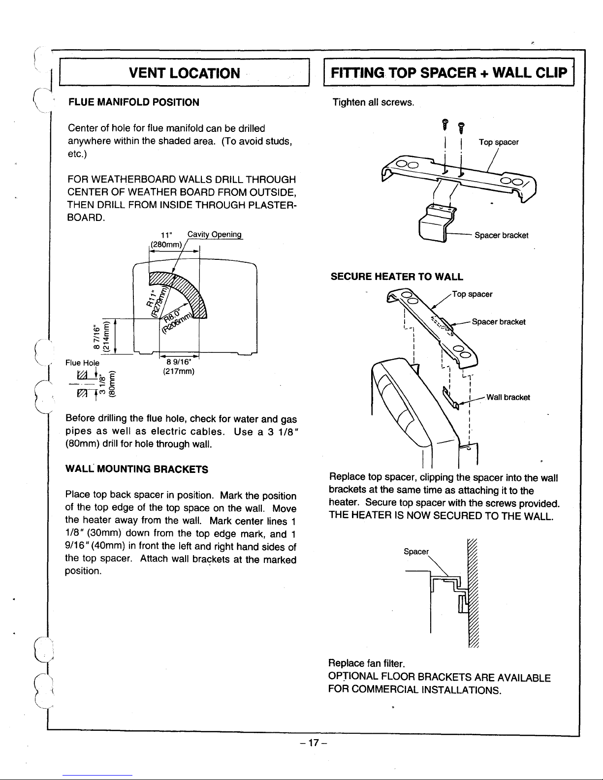
( FLUE MANIFOLD POSITION
IFITTING TOP SPACER + WALL CLIP I
Tighten all screws.
Top spacer
Spacer bracket
Top spacer
Replace top spacer, clipping
th~
spacer into the wall
brackets at the same time as attaching it to the
heater. Secure top spacer with the screws provided.
THE HEATER IS NOW SECURED TO THE WALL.
Spacer
SECURE HEATER TO WALL
89/16"
(217mm)
Center of hole for flue manifold can be drilled
anywhere within the shaded area. (To avoid studs,
etc.)
FOR WEATHERBOARD WALLS DRILL THROUGH
CENTER OF WEATHER BOARD FROM OUTSIDE,
THEN DRILL FROM INSIDE THROUGH PLASTER-
BOARD.
Flue Hole
raja,
E
-.-
;:: E
~tC')
@.
WALL MOUNTING BRACKETS
Before drilling the flue hole, check for water and gas
pipes
as
well as
electric
cables.
Use
a 3
1/8"
(80mm) drill for hole through wall.
Place top back spacer
in
position. Mark the position
of the top edge of the top space on the wall. Move
the heater away from the wall. Mark center lines 1
1/8" (30mm) down from the top edge mark, and 1
9/16" (40mm)
in
front the left and right hand sides of
the top spacer. Attach wall
braqkets at the marked
position.
Replace fan filter.
OPTIONAL FLOOR BRACKETS ARE AVAILABLE
FOR COMMERCIAL INSTALLATIONS.
-17-
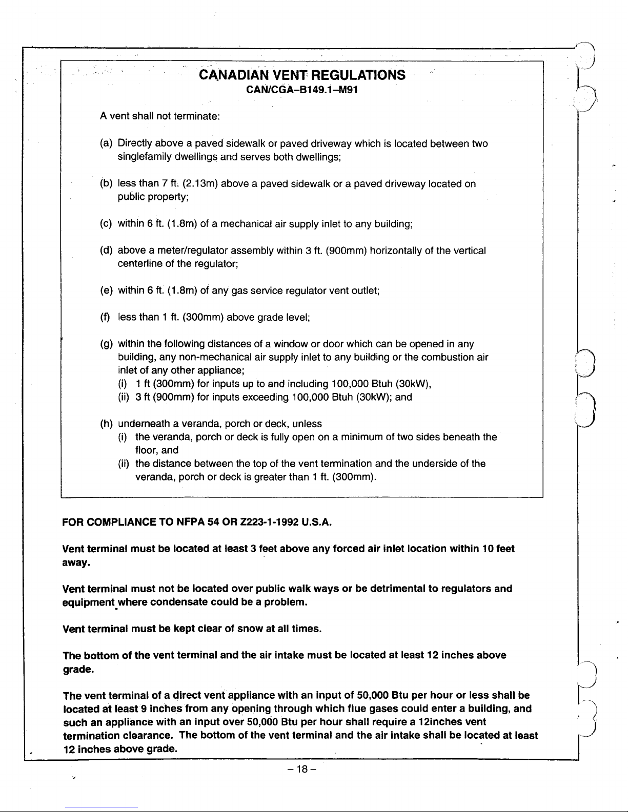
.CJ\NADIAN VENT REGULATIONS
CAN/CGA-B149.1-M91
A vent shall not terminate:
(a) Directly above a paved sidewalk or paved driveway which is located between two
singlefamily dwellings and serves both dwellings;
(b) less than 7ft(2.13m) above a paved sidewalk or a paved driveway located on
public property;
(c) within 6
ft.
(1.8m) of a mechanical air supply inlet to any building;
(d) above a meter/regulator assembly within 3
ft.
(900mm) horizontally of the vertical
centerline of the regulator;
(e) within 6
ft.
(1.8m) of
any
gas service regulator vent outlet;
(f) less than 1
ft.
(300mm) above grade level;
(g) within the following distances of a windowordoor which can be openedinany
building, any non-mechanical air supply inlet to any building or the combustion air
inletofany other appliance;
(i) 1ft(300mm) for inputs up to and including 100,000 Btuh (30kW),
(ii) 3ft(900mm) for inputs exceeding 100,000 Btuh (30kW); and
(h) underneath a veranda, porch or deck, unless
(i) the veranda, porch or deck is fully open on a minimum of two sides beneath the
floor, and
(ii) the distance between the top of the vent termination and the underside of the
veranda, porch or deck is greater than 1
ft.
(300mm).
FOR COMPLIANCE
TO
NFPA54OR Z223-1-1992 U.S.A.
Vent
terminal
mustbelocatedatleast
3 feet
above
any
forced
air
inlet
location
within10feet
away.
Vent
terminal
must
notbelocated
over
public
walk
waysorbe
detrimentaltoregulators
and
equipment.where
condensate
couldbea
problem.
Vent
terminal
mustbekept
clearofsnow
at all
times.
The
bottomofthe
vent
terminal
and
the
air
intake
mustbelocatedatleast12inches
above
grade.
The
vent
terminalofa
direct
vent
appliance
withaninputof50,000
Btu
per
hourorless
shall
be
locatedatleasl9
inches
from
any
opening
through
which
flue
gases
could
enterabuilding,
and
suchanappliance
withaninput
over
50,000
Btu
per
hour
shall
requirea12inches
vent
termination
clearance.
The
bottomofthe
vent
terminal
and
the
air
intake
shallbelocatedatleast
12
inches
above
grade.
-18
-
~~J
J
~;~,
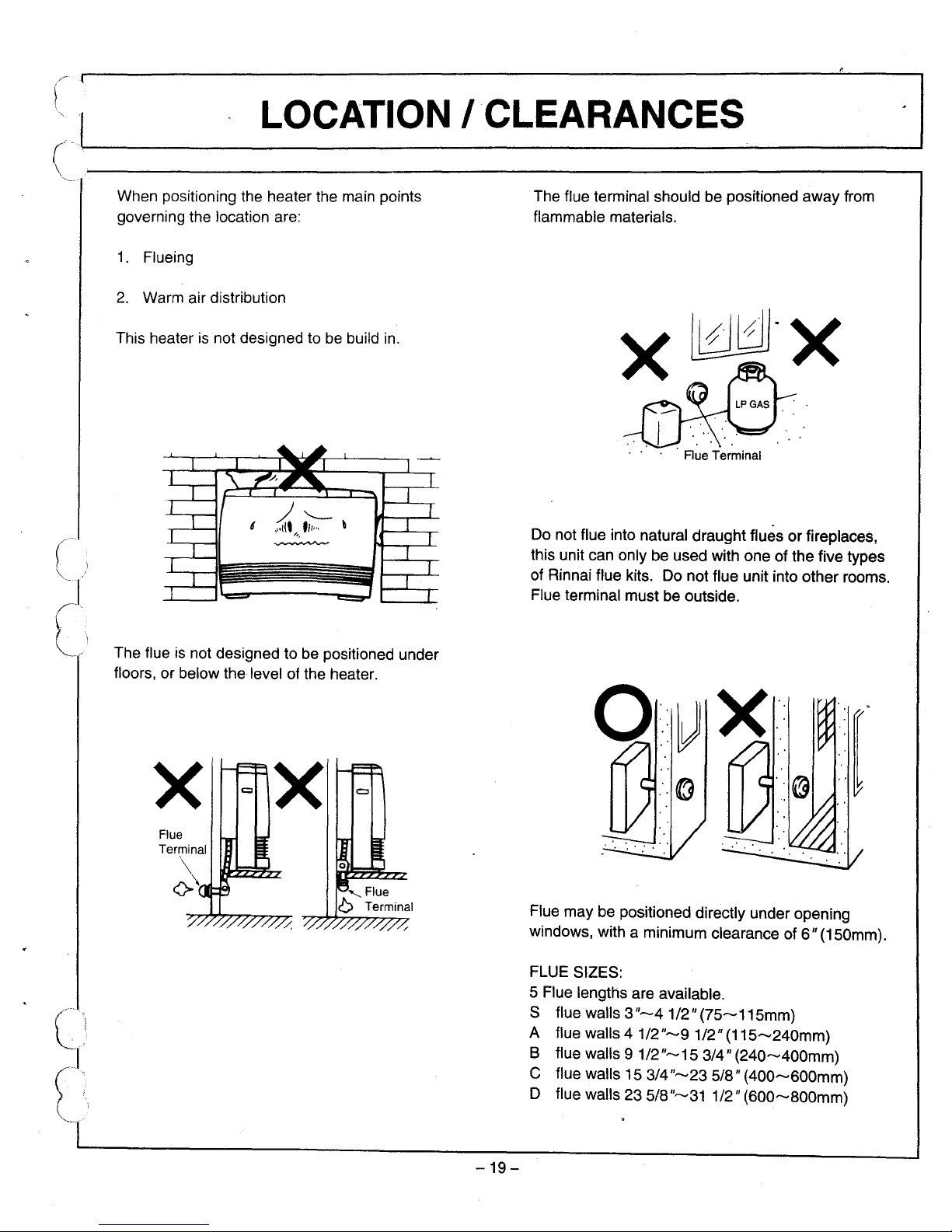
L_O_CA_J_IO_N_/C_L_E_A_R_A_N_C_E_S~_-----J-I
(
[I
When positioning the heaterthe main points
governing the location are:
1.
Flueing
2.
Warm air distribution
This heater is not designed to be build in.
The flue is not designed to be positioned under
floors, or below the level of the heater.
The flue terminal should be positioned
away
from
flammable materials.
x~-x
Flue Terminal
Do not flue into natural draught fluesorfireplaces,
this unit can only be used with one of the five types
of Rinnai flue kits. Do not flue unit into other rooms.
Flue terminal must be outside.
c
(
x
Flue
Terminal
x
-19-
Flue may be positioned directly under opening
windows, with a minimum clearance of6"(150mm).
FLUE SIZES:
5 Flue lengths are available.
S flue walls 3
"-4
1/2"
(75-115mm)
A flue walls
41/2"-91/2"
(115-240mm)
B flue walls
91/2"-15
3/4"
(240-400mm)
C flue walls 15
3/4"-23
5/8"
(400-600mm)
D flue walls 23
5/8"-31
1/2"
(600-800mm)
 Loading...