

Rinnai RHFE-201FA, RHFE-263FA, RHFE-431FA, RHFE-1004FA, RHFE-201RFA Service Manual
...
Direct Vent
Service Manual
RHFE-551FA
RHFE-1001FA
RHFE-1001FA/VA
RHFE-201FA
RHFE-263FA, FAII
RHFE-431FA, FAII, FAIII, WTA
RHFE-556FA, FAII, FAIII, FTRA, FTRAIII, WTA
RHFE-1004FA
ES08 RHFE-201RFA
ES11 RHFE-263RFA
ES17 RHFE-433RFA
EX17 RHFE-433RWTA
ES22 RHFE-558RFA
EX22 RHFE-558RWTA
ES38 RHFE-1004RFA, RHFE-1004FTA
EX08C RHFE-202FTA
EX11C RHFE-265FTA
EX17C RHFE-434FTA
EX22C RHFE-559FTA
200000014 Rev A
5/2012

Table of Contents
General Information .................................................... 3
Specifications ............................................................. 4
Sequence of Operations ............................................. 6
Fault Isolation
Accessing Fault Codes ............................................ 7
Fault Isolation Codes ............................................... 9
Fault Isolation - Other Issues ................................ 11
201FA, 201RFA
Troubleshooting .................................................... 12
Wiring Diagram ..................................................... 14
Ladder Diagram .................................................... 15
263FA, 263FAII, 263RFA
Troubleshooting .................................................... 16
Wiring Diagram ..................................................... 18
Ladder Diagram .................................................... 19
202FTA, 265FTA
Troubleshooting .................................................... 20
Wiring Diagram ..................................................... 21
Ladder Diagram .................................................... 22
431FA Series, 556FA/FTRA Series
Troubleshooting .................................................... 23
Wiring Diagrams
431FA Series, 556FA/FTRA ........................... 26
556FAIII .......................................................... 27
556FTRAIII...................................................... 28
431WTA, 556WTA
Troubleshooting .................................................... 29
Wiring Diagrams (431WTA) .................................. 32
Wiring Diagrams (556WTA) .................................. 33
433RFA, 558RFA
Troubleshooting .................................................... 34
Wiring Diagram ..................................................... 35
Ladder Diagram .................................................... 36
433RWTA, 558RWTA
Troubleshooting .................................................... 37
Wiring Diagram ..................................................... 38
Ladder Diagram .................................................... 39
434FTA, 559FTA
Troubleshooting ................................................... 40
Wiring Diagram ..................................................... 41
Ladder Diagram .................................................... 42
551FA, 1001FA, 1001FA/VA
Troubleshooting (551FA) ...................................... 43
Fault Finding Charts .............................................. 45
Wiring Diagram (551FA) ....................................... 55
Troubleshooting (1001FA) .................................... 56
Fault Finding Charts .............................................. 58
Wiring Diagram (1001FA) ..................................... 61
Troubleshooting (1001FA/VA) .............................. 62
Fault Finding Charts ............................................. 64
Wiring Diagram (1001FA/VA) ............................... 68
Lockout Check List ............................................... 69
1004FA, 1004RFA, 1004FTA
Troubleshooting Information ............................. 71
Wiring Diagram .................................................. 73
Ladder Diagram ................................................ 74
Lockout Check List ............................................ 75
Extension Installation Requirements ...................... 76
Vent Kits and Extension Sets .................................. 78
Vent Extension Covers ............................................ 79
Installations at Altitude ............................................. 79
Gas Pressure Setting Procedure
201FA, 263FA, 263FAII .................................... 80
201RFA, 263RFA .............................................. 82
202FTA, 265FTA ............................................... 85
431FA/WTA, 556FA/WTA ................................. 87
433RFA, 558RFA .............................................. 89
433RWTA, 558RWTA ....................................... 92
434FTA, 559FTA ............................................... 95
1004FA .............................................................. 97
1004RFA, 1004FTA .......................................... 98
Dip Switch Settings ................................................ 101
Checking Micro-Amps
(431, 556, 201, 263) .............................................. 102
Setting up the U Tube Manometer
(431, 556, 201, 263) .............................................. 103
Thermistor .............................................................. 104
Flame Rectification ................................................ 104
Setting a Maximum Temperature .......................... 105
Harmonic Noise (1004FA) ..................................... 105
Removal of “OF” on New PC Board
Installation .............................................................. 106
Wire Diagram Abbreviations .................................. 110
Serial Number Format ........................................... 111
2 Rinnai Direct Vent Service Manual
General Information
Safety Definitions
This is the safety alert symbol. This symbol alerts you to potential hazards that can kill or hurt you and
others.
DANGER
WARNING
CAUTION
Indicates an imminently hazardous situation which, if not avoided, will result in death or
serious injury.
Indicates a potentially hazardous situation which, if not avoided, could result in death or
serious injury.
Indicates a potentially hazardous situation which, if not avoided, could result in minor or
moderate injury. It may also be used to alert against unsafe practices.
Using this Manual
Repairs should be performed by a qualified service technician.
The following information can be referenced for additional information.
• Operation and Installation Manual
• Conversion Manual
• Technical Bulletins
Technical Support
Technicians are available to assist in servicing issues. Contact Rinnai Technical Services at 1-800-621-9419.
Recommended Tools
• Volt/Ohm/Amp meter with test probes
• U tube type manometer with 14 inch water column (W.C.) scale, two hoses and two 1/8 inch taps
• assorted wrenches including a 3/16 Allen wrench
• assorted screw drivers
• leak solution or leak detector
WARNING
There are a number of live tests that are required when fault finding this product. Extreme care should be used at
all times to avoid contact with energized components inside the furnace. Before checking for resistance readings
disconnect the power source to the unit and isolate the item from the circuit (unplug it).
CAUTION
Label all wires prior to disconnection when
servicing controls. Wiring errors can cause
improper and dangerous operation.
Rinnai Direct Vent Service Manual 3
If any of the original wire as supplied with the appliance must
be replaced, it must be replaced with type 18 AWG wire or its
equivalent.
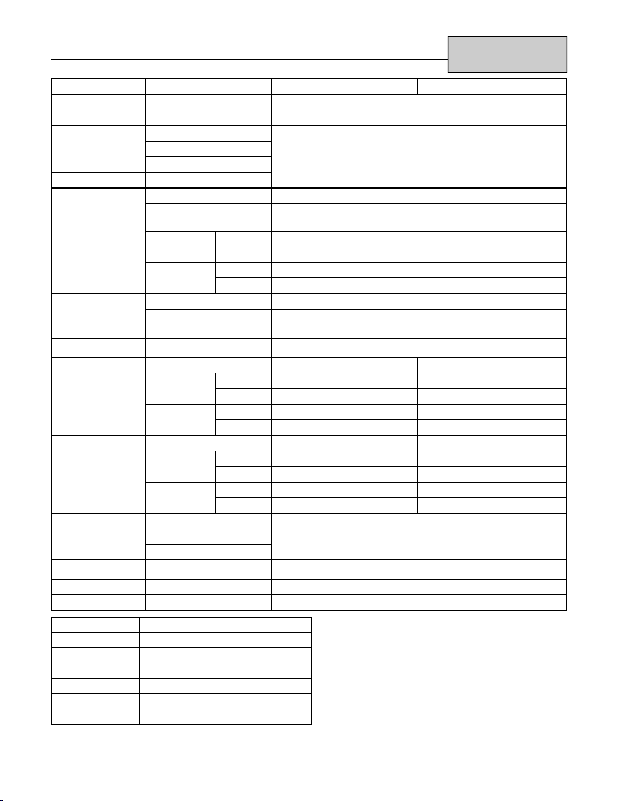
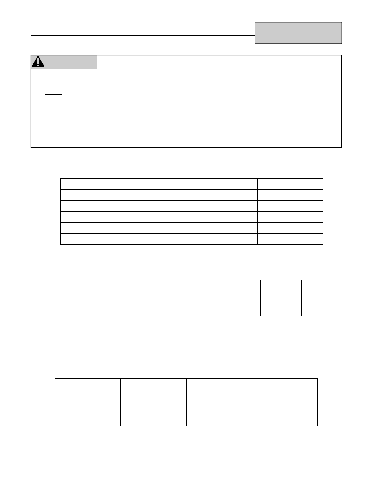
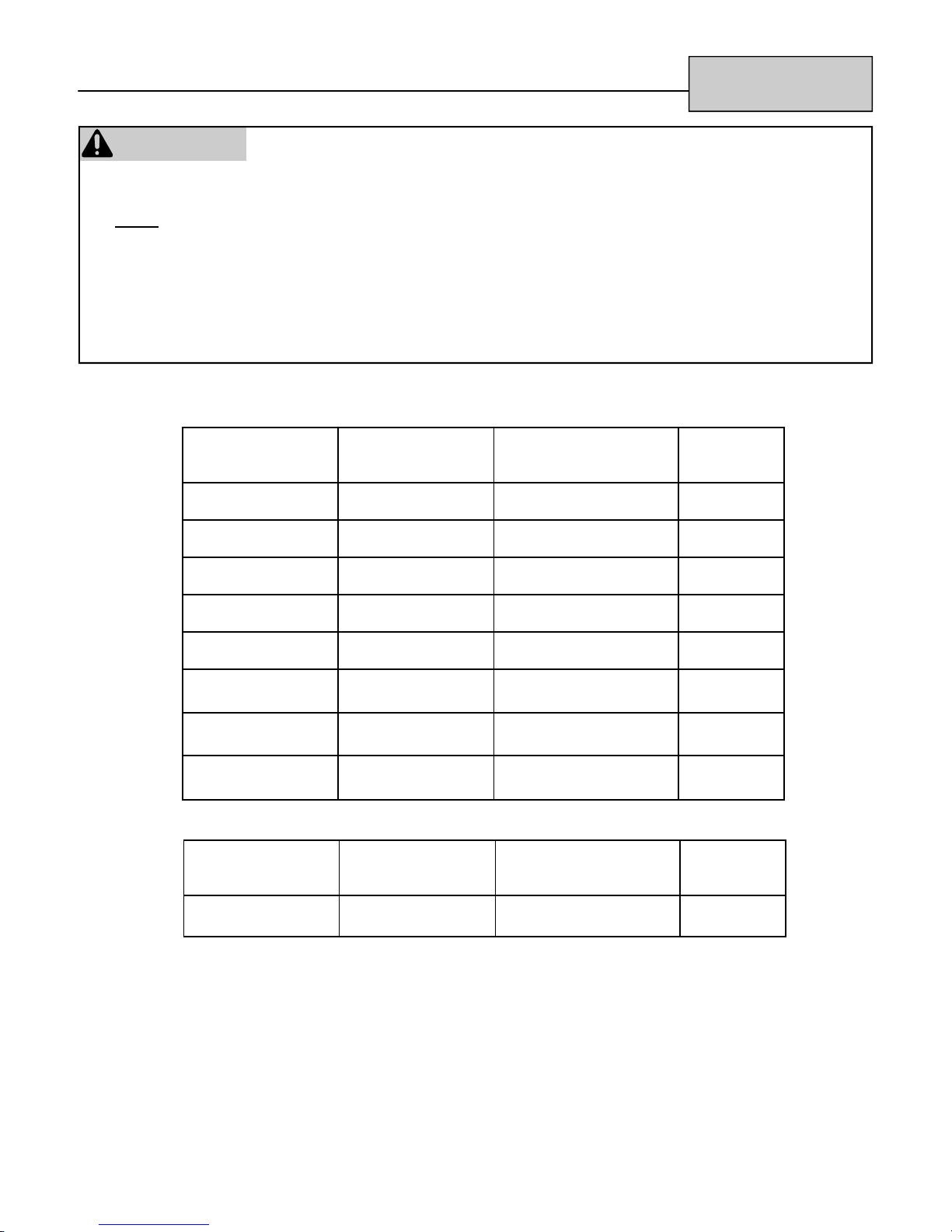
Specifications
1004FA
1001FA
551FA
(ES38)
1004RFA
265FTA
1001FA/VA
(ES38)
1004FTA
(EX11C)
11-13 in
-267 mm) W.C.
5.0-10.5 in (127
11-13 in
267 mm) W.C.
4.5-10.5 in (114-
11-13 in
267 mm) W.C.
5.0-10.5 in (127-
W.C.
3.5-10.5 in
(89-267 mm)
8-13 in
W.C.
(279-330 mm)
W.C.
(279-330 mm)
W.C.
(279-330 mm)
W.C.
(203-330 mm)
60 Hz,
120 watts
AC 120V,
60 Hz,
120 watts
AC 120V,
60 Hz,
121 watts
AC 120V,
60 Hz,
44 watts
AC 120V,
202FTA
(EX08C)
201FA 263FA, FAII
80.6% 80% 81% 80% 80.6% NA NA
3,000-8,000 5,500-11,000 3,000-8,000 5,500-11,000 10,500-38,400 22,000 (max) 38,400 (max)
3,000-8,000 5,700-11,000 3,000-8,000 5,700-11,000 10,500-36,500 21,000 (max) 36,500 (max)
BTU Input NG
BTU Input LP
AFUE Rating
W.C.
4.5-10.5 in
(114-267 mm)
W.C.
3.5-10.5 in
(89-267 mm)
83.4% 80% 82% 81% 82% NA NA
NG
AFUE Rating
LP
W.C.
4.5-10.5 in
(114-267 mm)
Gas Supply
Pressure (NG)
W.C.
8-13 in
(203-330 mm)
W.C.
8-13 in
(203-330 mm)
W.C.
8-13 in
(203-330 mm)
Gas Supply
Pressure (LP)
4 Rinnai Direct Vent Service Manual
60 Hz,
41 watts
AC 120V,
60 Hz,
47 watts
AC 120V,
60 Hz,
42 watts
AC 120V,
Electrical
Connection
(at high fire)
48.3-78.6 96.4-128.5 48.3- 78.6 96.4-128.5 203.4-360.6 135-189 179-289
27-34 dB(A) 31-38 dB(A) 27-36 dB 31-38 dB 37-47 dB(A) 35-44 dB(A) 35-46 dB(A)
Sound Level
Fan CFM
37 lbs (17 kg) 46 lbs (21 kg) 46 lbs (21 kg) 90 lbs (41 kg) 74 (34 kg) 110 (50 kg)
39.4 lbs
(17.9 kg)
Weight
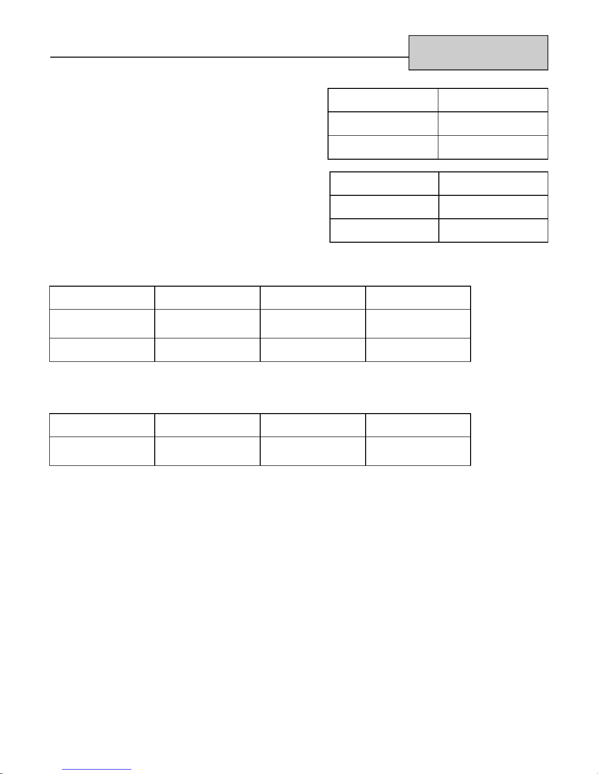
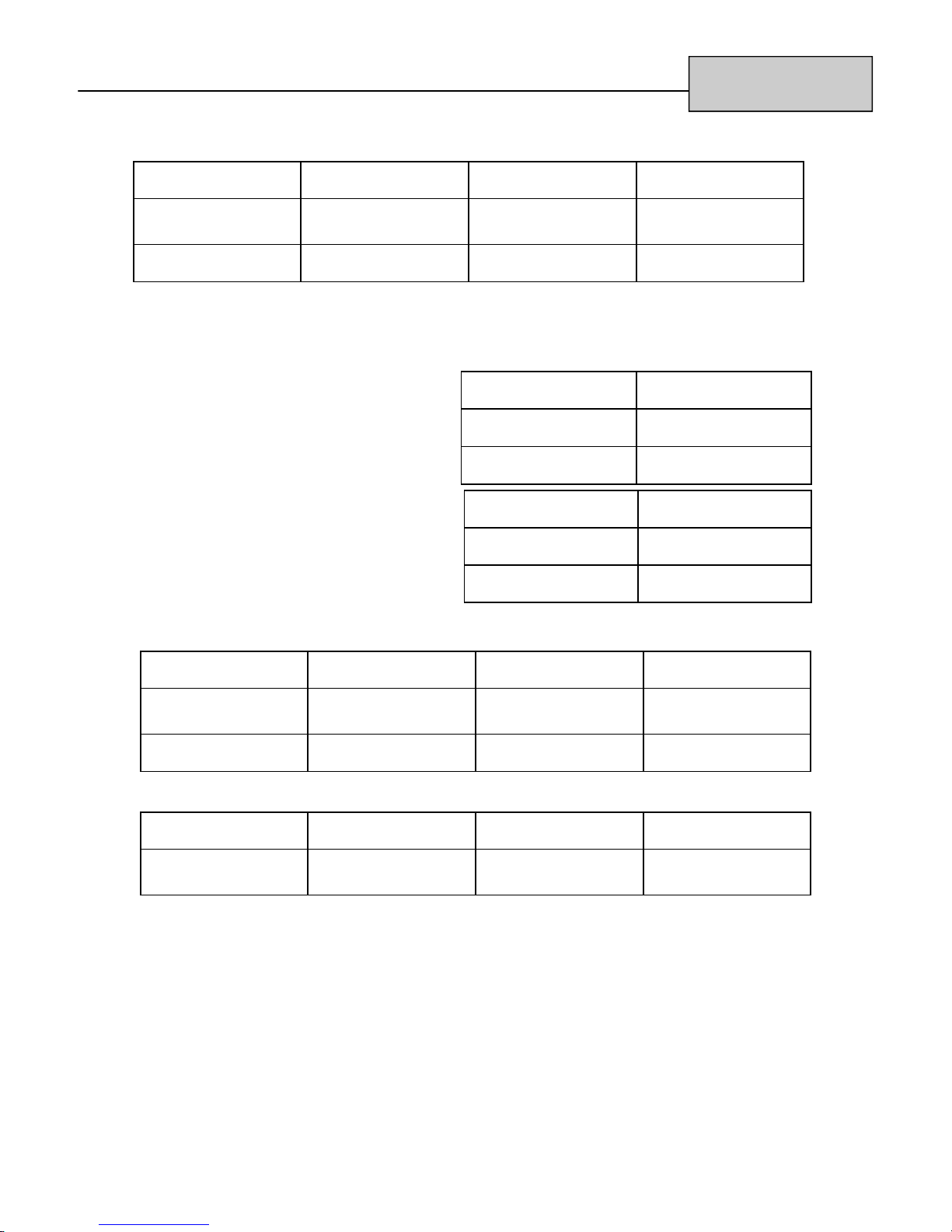
Specifications
559FTA
(EX22C)
434FTA
(EX17C)
(EX22)
558RWTA
(EX17)
433RWTA
80%
8,200-21,500
8,200-20,700
82%
W.C.
W.C.
W.C.
W.C.
8-13 in
8-13 in
8-13 in
8-13 in
3.5-10.5 in
(89-267 mm)
3.5-10.5 in
(89-267 mm)
3.5-10.5 in
(89-267 mm)
3.5-10.5 in
(89-267 mm)
W.C.
(203-330 mm)
W.C.
(203-330 mm)
W.C.
(203-330 mm)
W.C.
(203-330 mm)
60 Hz,
46 watts
AC 120V,
60 Hz,
46 watts
AC 120V,
60 Hz,
47 watts
AC 120V,
60 Hz,
47 watts
AC 120V,
110.5-162.7
33-42 dB
57 lbs (26 kg)
(ES22)
558RFA
(ES17)
433RFA
Series, WTA
556FA/FTRA
431FA
Series, WTA
8,200-16,700 8,200-21,500 8,200-16,700 8,200-21,500 8,200-16,700 8,200-21,500 8,200-16,700
8,200-16,700 8,200-20,700 8,200-16,700 8,200-20,700 8,200-16,700 8,200-20,700 8,200-16,700
W.C.
3.5-10.5 in
(89-267 mm)
W.C.
3.5-10.5 in
(89-267 mm)
W.C.
5.0-10.5 in
(127-267 mm)
80.8% 80.6% 81% 81% 81% 80.6% 81%
81% 81% 80% 80% 81% 81% 82%
W.C.
3.5-10.5 in
(89-267 mm)
W.C.
8-13 in
(203-330 mm)
W.C.
8-13 in
(203-330 mm)
W.C.
8-13 in
(203-330 mm)
W.C.
8-13 in
(203-330 mm)
60 Hz,
50 watts
AC 120V,
60 Hz*,
45 watts
AC 120V,
60 Hz*,
55 watts
AC 120V,
60 Hz*,
40 watts
AC 120V,
32-38 dB(A) 32-41 dB(A) 32-42 dB 32-39 dB 32-41 dB 32-41 dB 33-38 dB
110.5-141.3 110.5-162.7 110.5-141.3 110.5-162.7 110.5-141.3 110.5-162.7 110.5-141.3
51 lbs (23 kg) 51 lbs (23 kg) 53 lbs (24 kg) 53 lbs (24 kg) 51 lbs (23 kg) 51 lbs (23 kg) 57 lbs (26 kg)
BTU Input
BTU Input LP
NG
Rinnai Direct Vent Service Manual 5
AFUE Rating
NG
AFUE Rating
LP
Gas Supply
Pressure
(NG)
Gas Supply
Pressure
(LP)
Electrical
Connection
(at high fire)
Sound Level
Weight
Fan CFM
* 60 Hz must be maintained or the sound levels (dB) may change.

Sequence of Operations
1. The blower (combustion) motor fan starts and purges the combustion and heat exchanger
chambers making sure that they are clear. The green LED light is on.
2. The blower stages down and the ignition module powers the spark igniter and spark
occurs. When the spark is sensed as being correct, the PCB allows voltage to the
solenoid gas valves and gas enters the chamber. Ignition occurs and the flame rod begins
to prove flame. The blower motor stages back up to high. When the burner is on the LED
glows red indicating the burner is on. If the flame is correct and a secure ground is
available, then the flame rod produces micro-amps and the unit will fire trying to reach your
set room temperature.
3. The convection (room blower) will start on low speed circulating warm air into the structure.
After the PCB compares the set temperature to the room temperature, the seven stage gas
valve and fan control will fire the unit at the most efficient rate to obtain the comfort level as
set.
4. The negative co-efficient thermistor will sense the room temperature at the floor level and
will provide feedback to the PCB to determine the firing rate, fan speed, and run time.
When the set temperature is reached, the red indicator will return to green indicating the
burner is off. The convection fan will continue to run cooling the exchangers and
electronics for about 4 minutes.
5. The LED will be green indicating the unit is on standby. When the structure temperature
drops, the process starts over again.
6. Fresh air for combustion is drawn from outside and exhaust air is eliminated to the outside.
Moisture coming from the vent outside is normal as most high efficient units produce
moisture.
6 Rinnai Direct Vent Service Manual
Fault Isolation
If there is a malfunction the appliance may shut down
as a safety precaution and display a fault code to
assist in diagnosing the problem. The fault code will
flash in the display on the control panel.
Fault codes should be used to assist in identifying the
cause of the failure.
Accessing Fault Codes
Up to 10 fault codes are stored in the PC Board and can be recalled by simultaneously pressing the “Economy”
button and both temperature control buttons for 2.5 seconds while the appliance is turned OFF. After the buttons
are released, the fault codes will be displayed in 2 second intervals beginning with the most recent fault code.
Models with analog controls and models with digital LED’s each have their own set of fault codes.
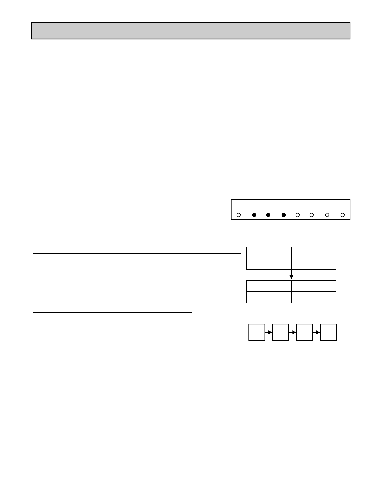
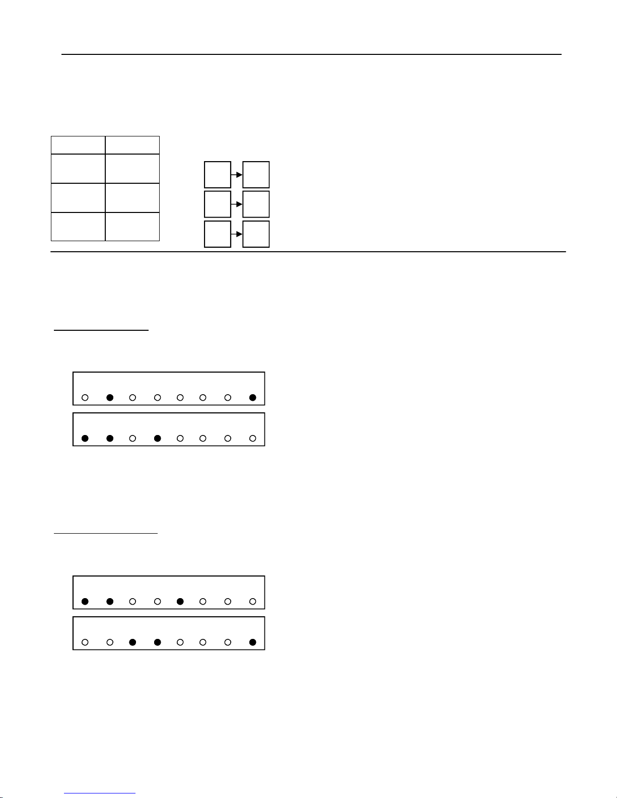
Models with analog controls:
The fault code will display by lighting up 1 to 4 of the temperatures at
the same time. For example, if the temperatures 60, 64, and 68 are lit
up then the fault code is 60*64*68 - Abnormal Combustion Fan RPM.
After the problem has been corrected, the fault code
will clear only after the appliance has been turned off
and back on. The code will be stored into the memory.
Some faults may cause a hard lockout where the
appliance shuts off and corrective action is required
before the appliance will operate.
LO 60 64 68 72 76 80 HI
On models RHFE-431WTA, RHFE-556WTA, RHFE-556FTRA:
Under SET the codes in memory are numbered 1 through 10 with “1” as the
most recent. Under ROOM the fault code will be displayed.
On models all other models with digital controls:
The codes in memory are numbered 1 through 10 with “1” as the most
recent. The temperature display will show “1” and then show the most
recent fault code. A “2” will then be displayed followed by the second
most recent fault code. The 10 most recent fault codes will be displayed
in this manner.
SET ROOM
1 61
SET ROOM
2 14
1 61 2 14
Rinnai Direct Vent Service Manual 7
Accessing Operation History
RHFE-431WTA,
RHFE-556WTA,
RHFE-433RWTA,
RHFE-558RWTA
SET ROOM
RHFE-201FA,
RHFE-263FA,
RHFE-263FAII,
RHFE-1004FA,
RHFE-556FTRA,
RHFE-1004RFA,
RHFE-1004FTA
RHFE-201RFA,
RHFE-263RFA,
RHFE-433RFA,
RHFE-558RFA,
RHFE-202FTA,
RHFE-265FTA
After the fault codes, the heater will display the
combustion hours, combustion cycles (number of
times the unit is turned on and off), and power
failure frequency.
50 82
18 42
1 25
50 82
18 42
1 25
5082 combustion hours
18420 combustion cycles (multiply displayed number by 10)
125 power failures
RHFE-431FA, RHFE-556FA
After the fault codes, the heater will display the combustion hours and combustion cycles (number of times the
unit is turned on and off). The combustion time will display first in two parts followed by the combustion cycles
displayed in two parts.
Combustion Time
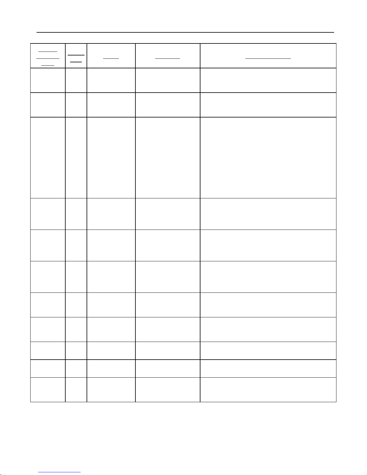
1. The temperature display will indicate a 16 digit binary number. A light indicates a “1”. A position not lighted,
indicates a “0”. Read this number using the example below.
LO 60 64 68 72 76 80 HI
LO 60 64 68 72 76 80 HI
This indicates the first 8 digits as follows: 0 1 0 0 0 0 0 1
This indicates the next 8 digits as follows: 1 1 0 1 0 0 0 0
2. Use a calculator with binary and decimal functions. Set the calculator to binary, “BIN”, and enter the 16 digits.
(0 1 0 0 0 0 0 1 1 1 0 1 0 0 0 0 in the example above.)
3. Press the decimal function, “DEC”, and the combustion time in hours will display. The combustion hours in
this example is 16848.
Combustion Cycles
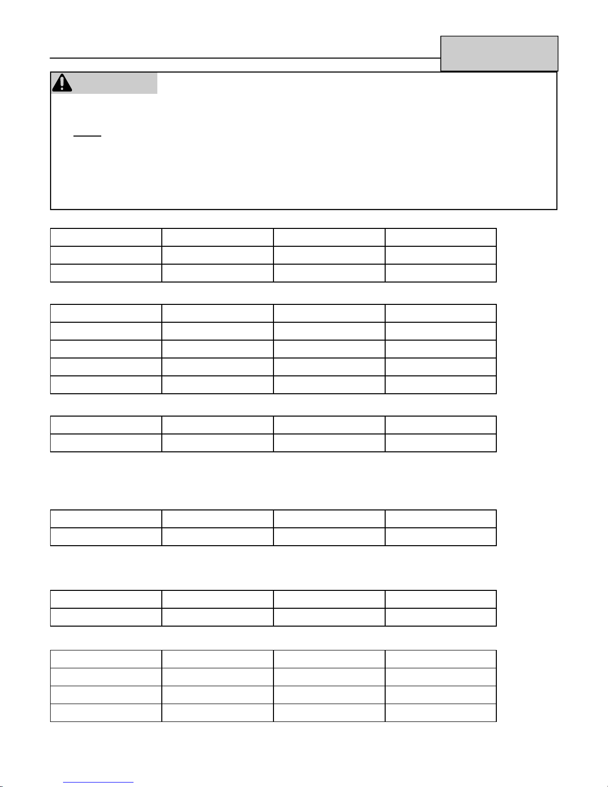
1. The temperature display will indicate a 16 digit binary number. A light indicates a “1”. A position not lighted,
indicates a “0”. Read this number using the example below.
LO 60 64 68 72 76 80 HI
LO 60 64 68 72 76 80 HI
2. Use a calculator with binary and decimal functions. Set the calculator to binary, “BIN”, and enter the 16 digits.
(1 1 0 0 1 0 0 0 0 0 1 1 0 0 0 1 in the example above.)
3. Press the decimal function, “DEC”, and multiply the displayed number by 10 to obtain the combustion cycles.
The combustion cycles in this example is 512,490.
This indicates the first 8 digits as follows: 1 1 0 0 1 0 0 0
This indicates the next 8 digits as follows: 0 0 1 1 0 0 0 1
8 Rinnai Direct Vent Service Manual
Fault Isolation Codes
Analog
Indicator
Light
LO-HI PF --
60 11 Missed Ignition Flame rod current
LO 12 Flame Failure Flame rod current
Digital
LED
:--
Name Definition Corrective Action
Power Failure Electric power has
been lost while the
appliance was running
does not reach 1.0
microamp within a
certain time after the
solenoid opens.
remains below 1.0
microamp for 3
seconds during initial
combustion
Check that the power cord is firmly inserted into
the electrical outlet.
Check the 3 amp fuse.
Check whether the fuse or breaker has blown at
Check that the flame rod is firmly positioned.
Check the flame rod lead.
Check the flame rod for carbon build up.
Check that the correct gas is being used.
Check the supply pressure at the meter and at
the appliance.
Check that there are no leaks in the gas supply
line or appliance.
Check for air in the gas supply.
Check that the correct gas is being used.
Check the supply pressure at the meter and at
the appliance.
Check that there are no leaks in the gas supply
line or appliance.
Check for air in the gas supply.
68 14 Overheat Safety
Device
HI 16 Over
Temperature
Cut Off
72 76 31 Room
Temperature
Thermistor
Disconnection
76 80 32 Room
temperature
thermistor short
circuit
High limit temperature
thermistor or thermal
fuse has activated
Room temperature is
above 104ºF for
longer than 10
minutes
Room temperature
thermistor circuit is
open
Room temperature
thermistor wire is
trapped or touching
bare metal.
Check that the correct gas is being used.
Check the supply pressure at the meter and at
the appliance.
Check that the flue terminal is not blocked.
Check that the air filter is not blocked.
Check that the warm air flow is not blocked.
(There should be a clearance of 40 inches in front
of the appliance.)
Check the circuit. (troubleshooting)
Check the circuit. (troubleshooting)
Rinnai Direct Vent Service Manual 9
Fault Isolation Codes
Analog
Indicator
Light
64 68 72 33 High-limit
68 72 76 34 High-limit
LO 60 64 53 Abnormal spark
60 64 68 61 Abnormal
Digital
LED
Name Definition Corrective Action
thermistor
disconnection
thermistor short
circuit
sensed
Combustion Fan
RPM
High limit thermistor
circuit is open.
High limit thermistor
wire is trapped or
touching bare metal.
• Sparker is not off
within 20 seconds of
ignition.
• 1st spark is not
sensed within 2
seconds
• 2nd spark is not
continuous for 1
second after
solenoid valve
opens
RPM is not achieved
within a certain time or
exceeds the RPM
limit.
Check the circuit. (troubleshooting)
Check the circuit. (troubleshooting)
Replace sparker
Check for obstacle preventing fan from turning
freely.
Check wiring harness to motor for damage or
loose connections.
64 68 70 ON/OFF Switch
Failure
LO 60 71 Solenoid Valve
Failure
80 72 Flame Rod
Failure
72 76 80
HI
NA 49 Pressure Sensor No signal from the
NA 99 Flue Block The pressure sensor
60 64 68
72 76
73 Communication
Failure
NA Flue Block Flue blockage has
The ON/OFF switch
connects continuously
for more than 15
seconds.
For either solenoid
valve, SV1 or SV2, the
signal and response
signal are different.
Flame rod output does
not cease within 20
seconds
Data transfer between
CPU and E2PROM
fails.
pressure sensor.
signal is below its limit.
been detected based
on fan speed.
Check the circuit. (troubleshooting)
Replace switch.
Check the circuit. (troubleshooting)
Replace gas valve.
Check the circuit. (troubleshooting)
Replace flame rod.
Disconnect the power and re-apply power.
Check the circuit. (troubleshooting)
Check the flue and termination for proper
installation and blockage.
Check the flue and termination for proper
installation and blockage.
10 Rinnai Direct Vent Service Manual

Fault Isolation - Other Issues
AT IGNITION:
Heater does not operate.
Warm air does not flow when the burner
lights.
Smoke or strange smells are produced
on the first trial light up after installation.
Sharp clicking noised at ignition, or
when unit shuts down, or goes out.
DURING COMBUSTION:
Clunking noise when the thermostat
operates.
Unit is not heating room.
Is the heater plugged in?
Have the fuses or breaker blown at the fuse box / breaker panel?
Is there a power failure?
Is the air filter blocked?
Is anything blocking the outlet for the hot air?
Is the flue blocked?
The fan is started automatically after a short delay. This is to allow the
heat exchanger to warm up, helping to avoid cold draughts.
This is caused by grease, oil, or dust on the heat exchanger and will stop
after a short time.
This is simply expansion noise from the heat exchanger.
This is the sound of the solenoid gas valves opening and closing.
Is the air filter blocked?
Is the set temperature high enough?
Is the warm air outlet blocked by anything?
Are the doors and windows of the room closed?
Was the appliance correctly sized for the space?
Air filter is blocked or the louvers are
blocked.
Heater will not re-ignite after overheating Even after unit has cooled down, the heater does not ignite again. Repair
Allow heater to cool, clean air filter, and operate again.
is necessary by a qualified service provider.
DURING COMBUSTION:
Convection fan continues to run after
turning OFF
This is to remove the residual heat from the heat exchanger. The fan will
stop when the heater cools down.
OTHER POINTS:
Steam is discharged from the flue
terminal.
Unit shuts off without apparent reason. Check whether filters are blocked. Dirty filters will cause the heater to
Power Failure
High efficiency appliances tend to discharge water vapor on cold days.
This is normal.
overheat.
Switch OFF, then ON again when power is restored to re-set controls.
Rinnai Direct Vent Service Manual 11
Troubleshooting
RHFE-201FA
WARNING
There are a number of live tests that are required when fault finding this product. Extreme care should be used at
all times to avoid contact with energized components inside the furnace.
You MUST be a qualified service person before proceeding with these test instructions.
Before checking resistance readings, turn off power source to unit and then isolate each item to be checked from
the circuit by unplugging it.
When setting gas pressures on one of these units, please check the complete model number you are trouble-
shooting. Gas pressures and dip switches can vary among models. Always check the rating plate for complete
information and follow directions.
(AC IN) (Connector B)
Black-White 120 VAC CONNECTOR B Pin # 1-2
Black-Ground 120 VAC Pin #2-Ground
White-Ground 0 VAC Pin #1-Ground
(TR) Transformer: (Connector C) (AC Out)
Read voltage across: Voltage Potential Read resistance Pin Numbers
Grey-Grey 90-110 VAC 3-6 Pin #1-7
Red-Yellow 30-42 VAC 0.8-1.5 Pin #4-5
Blank pin-Grey 15-21 VAC 0.6-1.2 Pin #6-7
Grey-Black 180-220VAC 155-260 Pin #7-8
(SP) Sparker: (Connector D) (Voltage potential while Sparking)
Read voltage across: Voltage Potential Read resistance Pin Numbers
Red-Blue 85-100 VAC 100K-120K Pin #3-6
The spark must be sensed as being at the correct location and intensity before it will allow the gas valve to open. Check
across Pin # 1-2 at Connector F and you should read 4-6 VDC potential. When sparking, if the spark is in the right location and
intensity the voltage potential will drop to almost 0 (zero) and then return to the 4-6 VDC potential.
(SV1 and SV2) Main Solenoid Valves: (Connector D)
Read voltage across: Voltage Potential Read resistance Pin Numbers
Black-Yellow 85-90 VDC 700-1000 Pin #1-4
*Resistance across each coils terminals should be 1400-2000 when isolated.
(POV) Modulating Gas Valve (Co nnector G)
Read voltage across: Voltage Potential Read resistance Pin Numbers
Grey-Grey 6-16 VDC 80-90 Pin #2-6
(BL) Combustion Blower Motor: (Connector G) DC Motor 37VDC 8 Watts
Read voltage across: Voltage Potential Read resistance Pin Numbers
Black-White 7-12 VDC 8K-10K Pin #7-8
Yellow-White 4-5 VDC 4K-6K Pin #4-8
Red-White 10-30 VDC N/A Pin # 3-8
12 Rinnai Direct Vent Service Manual

Troubleshooting
(FM) Convection Fan Motor: (Connector E) Variable 100VAC Motor 60 Hz
Read voltage across: Voltage Potential Read resistance Pin Numbers
Black-Red 37-105 VAC 100-120 Pin #1-2
* Be sure to check for obstructions to blades. Check the capacitor before replacing motor.
(PS) Pressure Sensor: (Connector A) Omron Electronic Pressure Switch
RHFE-201FA
Omron Electronic
Note: Insure clear and black hose from pressure switch to blower air chamber is not blocked or
crimped with any obstructions including spider webs.
(TF 216ºC, OHS1 90ºC, OHS2 70ºC) (Connector G) Safety Circuit:
Disconnect connector G from PCB. Check for continuity reading from Pin #1 to Pin #5 on the wiring
harness White to White wires. If you do not read continuity through this circuit, locate open thermal
fuse, bimetal OHS1, or bimetal OHS2, and replace. You must immediately determine what caused
the overheat situation and correct. Check combustion specifications, gas pressures, gas type, and
for any obstructions to air flow.
(R.TH) Room Thermistor: (Co nnector H) Negative Co-efficient Therm istor
(the resistance decreases as the temperature increases)
Disconnect connector H from PCB. Set your meter to the 200K scale. Place your meter leads into
Yellow to Yellow. Apply heat to the thermistor bulb. The resistance will decrease. Apply cold and the
resistance will increase. Examples of readings:
41ºF=91K 50ºF=65K 68ºF=39K 86ºF=23K
(OH.TH) Over Heat Thermistor: (Connector H)
0.31 in (8.0 mm) WC
ON
0.11 in (2.8 mm) WC
OFF
5 VDC
Disconnect connector H from PCB. Set your meter to the proper scale. Place your meter leads
into White to White. A reading below 0.38k indicates a short. A reading above 1255k indicates
an open circuit or broken wire. Insure air flow is not obstructed.
(FR) Flame Rod (Connector C1)
Set your meter to read micro-amps (µ). Disconnect connector C1 and place your meter in series
with the Yellow to Yellow wires. Upon flame development you should read 1 -2 micro-amps.
Depending on gas type and firing rate you should read 4 to 8 micro-amps. You must have a
grounded and polarized electrical supply with no obstructions in burner or build up on flame rod to
proof flame. The micro-amp symbol on your meter is µ.
(Hard Lock Out Information)
Improper sized gas lines, low pressure drops, defective or freezing pressure regulators, improper
electrical supply and failure to ground, spider webs in burners, intake and exhaust air blockage of
vents, broken or damaged wiring harnesses, or blown fuses can cause hard lock outs. Before
replacing components in furnace, insure the above items are within the specifications. The above
listed items are not a warranty issue or defect in unit.
Rinnai Direct Vent Service Manual 13

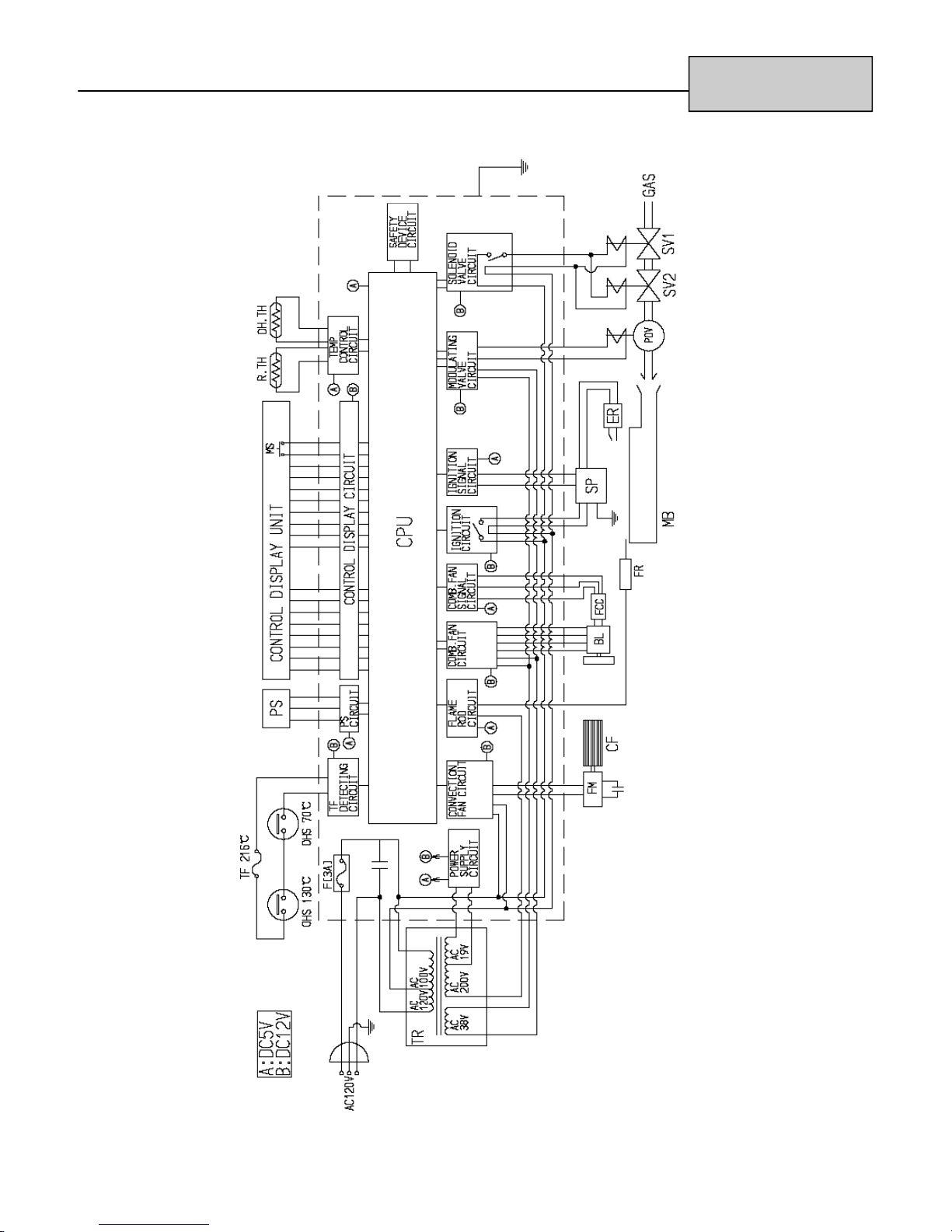
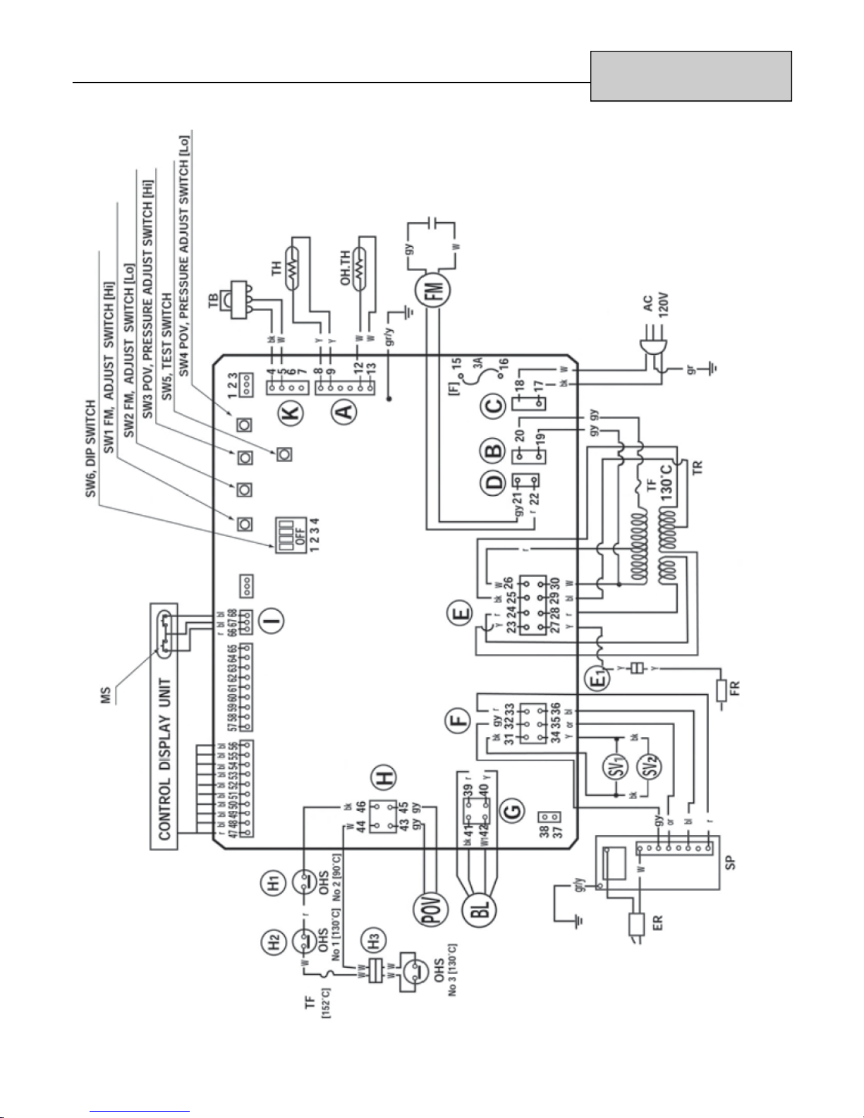
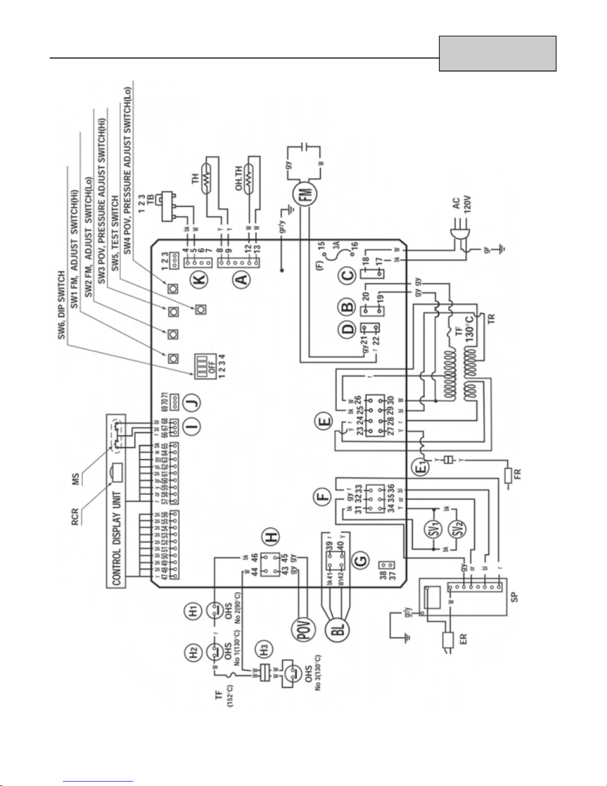
Wire Diagram
RHFE-201FA
RHFE-201RFA
14 Rinnai Direct Vent Service Manual
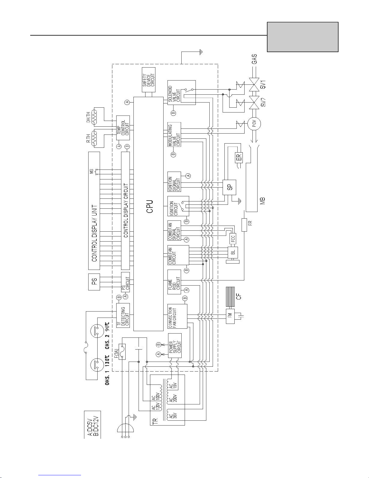
Ladder Diagram
RHFE-201FA
RHFE-201RFA
Rinnai Direct Vent Service Manual 15
Troubleshooting
RHFE-263FA
RHFE-263FAII
RHFE-263RFA
WARNING
(AC IN)
Black-White 120 VAC Pin # 1-2
Black-Ground 120 VAC Pin #2-Ground
White-Ground 0 VAC Pin #1-Ground
(TR) Transformer: (Connector CN2 AC Out)
Read voltage across: Voltage Potential Read resistance Pin Numbers
Gray - Gray 98-125 VAC 4--16 1-7
White - White 98-125 VAC 4--14 2-3
Red - Red 35 VAC 1--3 4-10
Black - Yellow 200-220 VAC 250--400 5-8
There are a number of live tests that are required when fault finding this product. Extreme care
should be used at all times to avoid contact with energized components inside the furnace.
You MUST be a qualified service person before proceeding with these test instructions.
Before checking resistance readings, turn off power source to unit and then isolate each item to be
checked from the circuit by unplugging it.
When setting gas pressures on one of these units, please check the complete model number you
are trouble-shooting. Gas pressures and dip switches can vary among models. Always check the
rating plate for complete information and follow directions.
Black - Blue 12-20 VAC 1--3 8-9
(SP) Sparker: (Connector CN4)
Read voltage across: Voltage Potential Read resistance Pin Numbers
Red-Blue 85-100 VAC 100K-120K 3-6
The spark must be sensed as being at the correct location and intensity before it will allow the gas valve to open. Check
across Pin # 1-2 at Connector F and you should read 4-6 VDC potential. When sparking, if the spark is in the right location and
intensity the voltage potential will drop to almost 0 (zero) and then return to the 4-6 VDC potential.
(SV1, SV2, POV) Main Solenoid Valves: (Connector CN4)
Read voltage across: Voltage Potential Read resistance Pin Numbers
SV1 - Yellow ~ Black (hold) 85-90 VDC 1400-2000 1-4
SV2 - Yellow ~ Black (assist) 85-90 VDC 1400-2000 1-4
POV - Gray ~ Gray 6-16 VDC 80-90 2-6
*Resistance across each coils terminals should be 1400-2000 when isolated.
(BL) Combustion Fan Motor: (Connector CN8) DC Motor 37VDC 8 Watts
Read voltage across: Voltage Potential Read resistance Pin Numbers
Black-White 7-12 VDC 8-10 K 7-8
Yellow-White 4-5 VDC 4-6 K 4-8
Red-White 10-30 VDC N/A 3-8
16 Rinnai Direct Vent Service Manual
Troubleshooting
RHFE-263FA
RHFE-263FAII
RHFE-263RFA
(FM) Convection Fan Motor: (Connector CN3) AC Motor 60 Hz, 100VAC
Read voltage across: Voltage Potential Read resistance Pin Numbers
Black-Red 40-105 VAC 100-120 1-2
* Be sure to check for obstructions to blades. Check the capacitor before replacing motor.
(PS) Pressure Sensor: (Connector CN13) Electronic Pressure Switch, 125 V, 0.1 A
Electronic
Note: Ensure clear and black hose from pressure switch to blower air chamber is not blocked or
crimped with any obstructions including spider webs.
(RT) Room Temperature Control:
Integrated into the PCB program and works in conjunction with the thermistor as noted below.
(TH) Room Thermistor:
Check thermistor by inserting meter leads into each end of thermistor plug. Set your meter to the
200 K scale. Apply heat to the thermistor bulb and the resistance should decrease. Apply cold
and the resistance should increase. Examples of readings:
41ºF=91K 50ºF=65K 68ºF=39K 86ºF=23K
(FR) Flame Rod
Set your meter to read micro-amps (µ). Located on the combustion chamber, the lfame rod proofs
flame for proper operations. A properly grounded electrical supply is a must. Flame rod current
through this rod should range between 4 to 8 icro amps depending on gas type. Low fire flame
current should be 1.2 to 2.0 micro amps.
Improperly setup and /or converted units can soot and cause hard lockouts. If carbon is found on the
flame rod, clean the carbon from it. Then you need to confirm your manifold differential gas pressure on
Hi fire and Lo fire is correct. Insure primary and secondary air dampers are correct. Also, check to ensure
proper orifices were placed in the unit..
IMPORTANT INFORMATION CONCERNING HARD LOCKOUTS:
Other items that can cause hard lockouts are: improper sized gas lines, low gas pressures or pressure drops due
to other appliances on the gas system, spider webs in the burner and air intake of vent system, improper ground
or no ground at receptacle, supply regulators freezing up or defective, voltage drops or bad receptacles, winds in
excess of 40 mph causing turbulence inside the vent terminal, etc.
(OHS1, OHS2, TF) Safety Circuit Check: CN8
Check for continuity reading from pin #1 white wire to pin #5 white wire. If you do not read continuity through this
circuit, locate defective switch and replace that component. Then determine what caused overheat condition.
(MS) Main Switch: CN11
Disconnect CN11 from PCB, being careful not to break wires. Read Blue to Blue, pin #9 and 10 on 40K . When
ON/OFF is in the ON position, you should read 10--18K. When released, you should read open or 0
Wiring harness, connectors, and fuses should be checked if all above readings are normal.
0.31 in (8.0 mm) WC
ON
0.11 in (2.8 mm) WC
OFF
5 VDC
Rinnai Direct Vent Service Manual 17
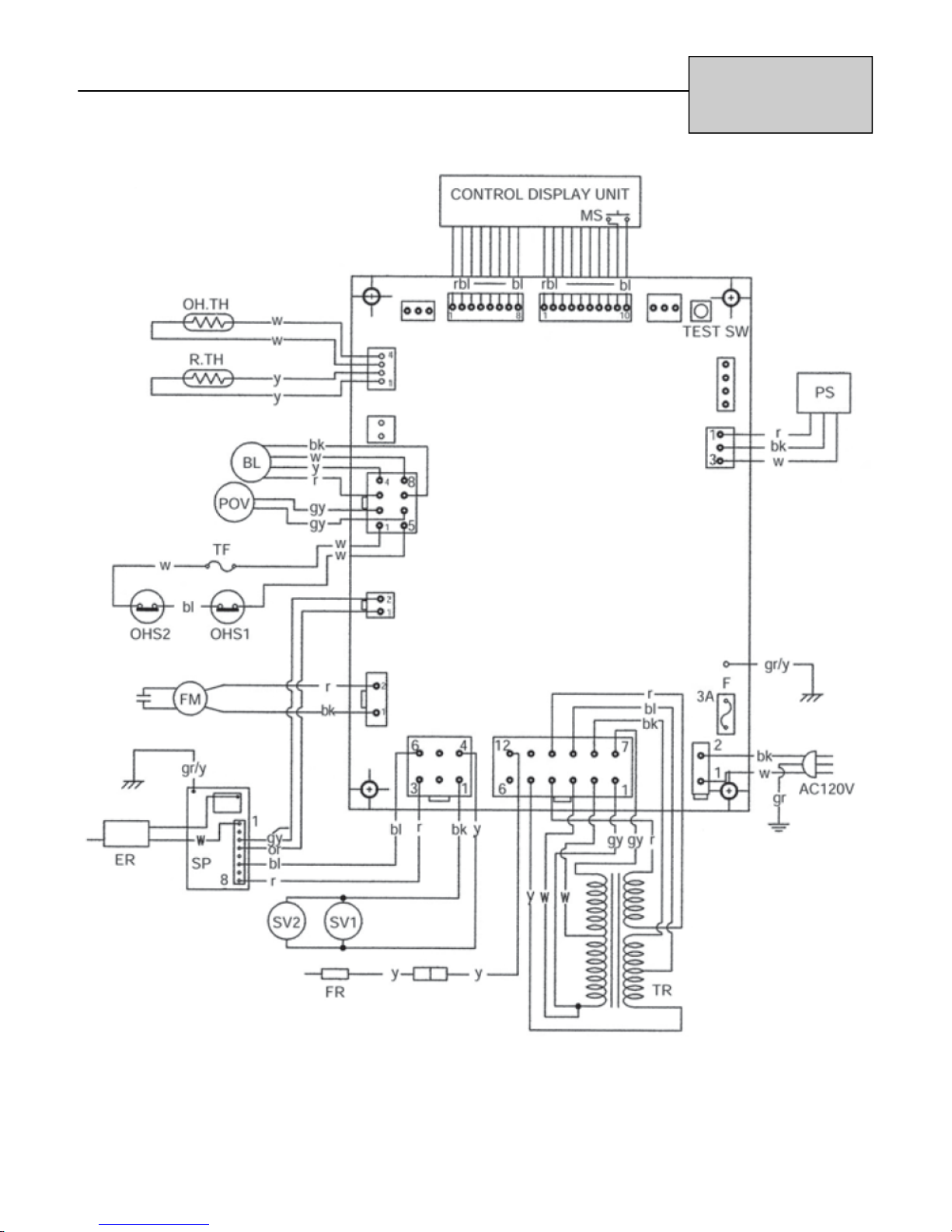
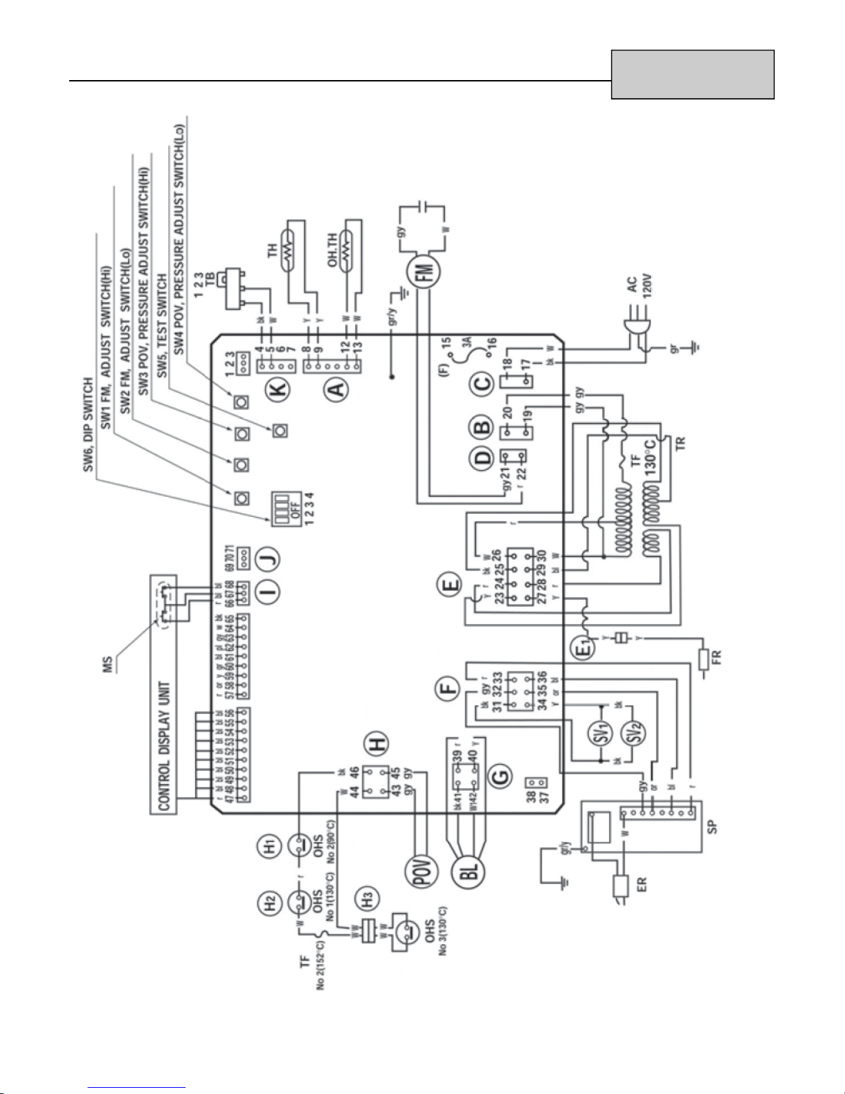
Wire Diagram
RHFE-263FA
RHFE-263FAII
RHFE-263RFA
18 Rinnai Direct Vent Service Manual
Ladder Diagram
RHFE-263FA
RHFE-263FAII
RHFE-263RFA
Rinnai Direct Vent Service Manual 19
Troubleshooting
Part Wire 202FTA 265FTA
Control Panel
OHS.
TF White - White (TF)
O.H. TH
Room
Thermistor
White - White
White - White
(TH operates)
Red - Blue
Blue - Blue
White - White
Blue - White (OHS1)
Blue - White (OHS2)
White - White 0.87-482k; (<0.87k:Short, >482k:Open)
Temperature
High Flashes below 4.5k
(Filter sign)
Yellow - Yellow 1.82-707k; (<1.82k:Short, >707k:Open)
Temperature
Low Flashes below 4.5k
High Operates below 3.4k
Low Operates below 3.4k
DC0-5V (Pulsed voltage); Resistance is infinity, but the current flows
when the switch is pushed.
Below DC 1V, Below 2
32°F (0°C):214k, 68°F (20°C):78k, 122°F (50°C):21k
176°F (80°C):7.3k, 212°F (100°C):3.6k, 135°F (275°C):1.5k
32°F (0°C):113k, 68°F (20°C):39k,
86°F (30°C):24k, 104°F (40°C):15k
RHFE-202FTA
RHFE-265FTA
FR Yellow - Yellow
White - Black Below ignition revolution +2Hz Below ignition revolution +2Hz
Combustion Fan
(In case of short
vent.)
Combustion Fan
(In case of long vent.)
Ignitor Red - Blue 90-120V
SV
Modulating Valve Red-White
Convection Fan Red - Black 50-110V, 90-180
Pressure Sensor Red - White DC3 - 7V
Ignition
revolution
Normal
revolution
White - Black - Below ignition revolution +2Hz
Ignition
revolution
Normal
revolution
Black-White
Black-Yellow
Initial LP: 75Hz, NG: 80Hz LP: 80Hz, NG: 85Hz
Re-attempt LP: 75Hz, NG: 80Hz LP: 80Hz, NG: 85Hz
High LP: 110Hz, NG: 110Hz LP: 128Hz, NG: 118Hz
Low LP: 83Hz, NG: 83Hz LP: 82Hz, NG: 81Hz
Initial - LP: 80Hz, NG: 85Hz
Re-attempt - LP: 80Hz, NG: 85Hz
High - LP: 128Hz, NG: 128Hz
Low - LP: 82Hz, NG: 89Hz
Below 0.1A (During Stop)
80-100V, 1.5-2.5k
DC2-15V(Low-High), 60-90
Transformer 60Hz-120V
Gray - Gray AC108-132V, 5-20
White - White AC95-120V, 5-20
Red - Red AC20-40V, 0.5-2.0
Brown - Brown AC10-30V, 1-5
Black - Blue AC10-30V, 1.0-3.0
Black - Yellow AC200-240V, 200-450
20 Rinnai Direct Vent Service Manual
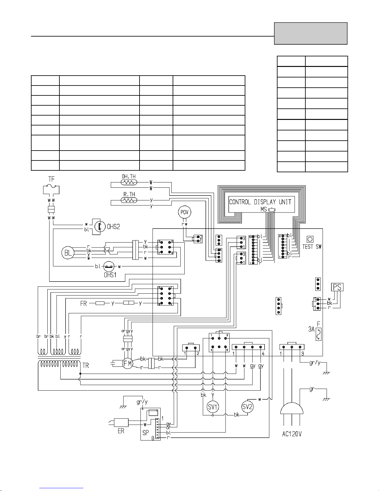
Wire Diagram
MARK PART NAME
MS MAIN SWITCH
R.TH THERMISTOR
TF THERMAL FUSE
F FUSE
ER ELECTRODE
POV MODULATING SOLENOID
VALVE
TR TRANSFORMER
FR FLAME ROD
MARK PART NAME
OH.TH OVER HEAT THERMISTOR
OHS1, 2 OVER HEAT SWITCH 1, 2
FM CONVECTION FAN MOTOR
SP SPARKER
SV1, 2 MAIN SOLENOID VALVE 1, 2
BL COMBUSTION FAN MOTOR
PS PRESSURE SENSOR
RHFE-202FTA
RHFE-265FTA
CODE COLOR
bk black
bl blue
gr green
gr/y green/yellow
r red
w white
y yellow
gy gray
or orange
br brown
Rinnai Direct Vent Service Manual 21
w
bk
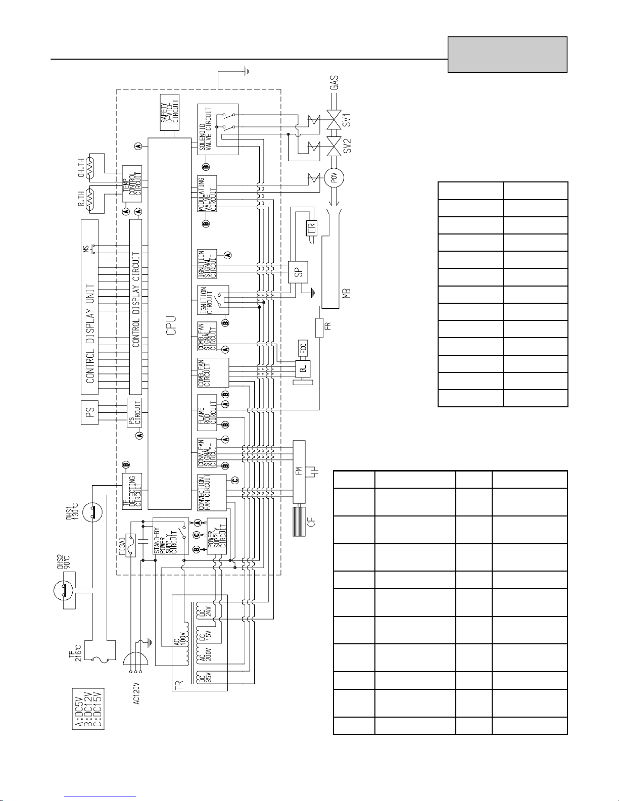
Ladder Diagram
RHFE-202FTA
RHFE-265FTA
CODE COLOR
bk black
bl blue
gr green
gr/y green/yellow
r red
w white
y yellow
gy gray
or orange
pk pink
br brown
lb light blue
MARK PARTS NAME MARK PARTS NAME
MS Main switch OH,
TH
R, TH Thermistor OHS1, 2 Over heat switch
TF Thermal fuse FM Convection fan
F Fuse SP Sparker
ER Electrode SV1, 2 Main solenoid
POV Modulating
solenoid valve
BL Combustion fan
Over heat
thermistor
1,2
motor
valve 1,2
motor
22 Rinnai Direct Vent Service Manual
TR Transformer FCC Fan control
circuit
FR Flame rod MB Main burner
PS Pressure sensor CPU Central
processing unit
CF Convection Fan
Troubleshooting
RHFE-556FA/FTRA Series
RHFE-431FA Series
WARNING
There are a number of live tests that are required when fault finding this product. Extreme care should be used at
all times to avoid contact with energized components inside the furnace.
You MUST be a qualified service person before proceeding with these test instructions.
Before checking resistance readings, turn off power source to unit and then isolate each item to be checked from
the circuit by unplugging it.
When setting gas pressures on one of these units, please check the complete model number you are trouble-
shooting. Gas pressures and dip switches can vary among models. Always check the rating plate for complete
information and follow directions.
(TR) Transformer:
Read Voltage across:
WIRE COLOR VOLTAGE RESISTANCE PIN NO.
White - White 98 - 105 VAC 6 - 19 ohms 26 - 30
Red - Red 28 - 50 VAC 1 - 3 ohms 24 - 28
Black - Blue 10 - 15 VAC 0.5 - 2 ohms 25 - 29
Blue - Yellow 130 - 185 VAC 200 - 400 ohms 23 - 29
Gray - Gray 110 - 120 VAC 10 - 14 ohms 19 - 20
(SP) Sparker Board:
WIRE COLOR
Blue - Red
Set your voltage meter on the 400k scale, unplug the (5) pin connector on the sparker board. When reading
across the two lugs the blue and red wire connect to, you should read somewhere between 100k and 120k ohms
of resistance. When checking the spark sensing circuit, check across the orange wire (pin #35) and grey wire (pin
#32) on your 40 VDC scale. You should read between 4 - 5 VDC. During the spark this voltage will drop to
approximately 0 VDC. Once unit ignites the voltage will go back up to 4 - 5 VDC.
(POV, SV1, and SV2) Gas valve solenoids:
VOLTAGE
85 - 110 VAC
RESISTANCE PIN
see below
33 - 36
WIRE COLOR VOLTAGE RESISTANCE * PIN NO.
Gray - Gray
Black - Yellow 85 - 90 VDC 1,300 - 2,000 ohms 31 - 34
*Remember, when reading the resistance of a solenoid coil, you should read across the lugs on the coil.
Rinnai Direct Vent Service Manual 23
4.5 VDC low fire to
11.5 VDC high fire
80 - 100 ohms 43 - 45
Troubleshooting
(BL) Combustion Motor:
NOTE: If your meter does not have a hertz scale, please
refer to voltage and resistance readings listed
below. If you have a hertz scale, check the
following items first. Hertz reading across black white wires, pins 41 and 42.
Voltage and resistance check for (BL).
WIRE COLOR VOLTAGE RESISTANCE PIN NO.
RHFE-431 - LP UNITS
Lo fire - 44 Hz.
Hi fire - 81 Hz.
RHFE-431 NG UNITS
Lo fire - 44 Hz.
Hi fire - 81 Hz.
RHFE-431FA Series
RHFE-556FA/FTRA Series
RHFE-556 LP UNITS
Lo fire - 47 Hz.
Hi fire - 106 Hz.
RHFE-556 NG UNITS
Lo fire - 48 Hz.
Hi fire - 106 Hz.
Red - Yellow
Black - White N/A 9.4 k - 9.9 k ohms 41 - 42
(FM) Convection fan motor:
WIRE COLOR VOLTAGE RESISTANCE PIN NO.
Red - Gray
(TH) Thermistor:
Check the thermistor by inserting meter leads into each end of the thermistor plug. Set your meter to the 200k
scale and read resistance. You should be able to apply heat to the thermistor bulb and see the resistance
decrease. Then apply ice to the thermistor bulb and the resistance should increase.
EXAMPLES: 41 °F = 91 k ohms
50 °F = 65 k ohms
68 °F = 39 k ohms
86 °F = 23 k ohms
(FR) Flame Rod:
Flame rod - yellow wire = pin #27. Low fire current should be 1.3 to 2.0 micro amps (Fa). High fire current should
be 4 to 8 micro amps, depending on gas type being used.
NOTE: Improperly setup and/or converted units can soot and cause carbon to accumulate on flame rods. This
will cause hard lockouts. If carbon is found on the flame rod, remove and clean carbon from rod. Then
you will need to confirm manifold gas pressure, proper air dampers and ensure vent is clear. Also, check
for proper orifices.
1-2 VDC low fire to 7.6
-18 VDC high fire
80-94 VAC low fire to
95-104 VAC high fire
1.2 - 1.8 mega ohms 39 - 40
90-180 ohms 21 - 22
24 Rinnai Direct Vent Service Manual

Troubleshooting
(H
, H2 and H3) Safety Circuit:
1
Check for continuity across pins 44 and 46 at terminal H on the PC board. If you have no continuity, this means
one of these switch/thermal fuses is open. Replace defective component.
(OH - TH) Overheat Thermistor:
Check resistance reading across pins 12 and 13 at terminal A on the PC board. Proper readings should be 0.6 k
and 523 k. A reading below 0.6 k ohms indicates a short and a reading above 523k indicates an open circuit.
(MS) On/Off Control:
To check to ensure the on/off button is functioning, unplug terminal I. Place (1) lead of your meter on the red wire
for pin #66 and the other lead on the blue wire for pin#68. Now press the on/off button and you should be able to
read continuity through this switch each time the button is pressed.
(TB) Terminal Block:
This terminal is located on the right rear upper portion of the unit. On direct vents the jumper should be across
terminals 2 and 3. On units with vent extensions over four feet, this jumper should be across terminals 1 and 2.
IMPORTANT INFORMATION CONCERNING HARD LOCKOUTS:
Other items that can cause lockouts are: Improperly converted units, spider webs in burner and
air intake of vent system, improperly sized gas lines, low gas pressures or pressure drops due to other appliances
on the gas system, improper ground or no ground at receptacle, supply regulators freezing up or defective,
voltage drops or bad receptacle, winds in excess of 30 to 40 MPH causing turbulence inside the vent terminal, etc.
RHFE-556FA/FTRA Series
RHFE-431FA Series
Rinnai Direct Vent Service Manual 25
Wire Diagram
RHFE-431FA Series
RHFE-556FA/FTRA
26 Rinnai Direct Vent Service Manual
Wire Diagram
RHFE-556FAIII
Rinnai Direct Vent Service Manual 27
Wire Diagram
RHFE-556FTRAIII
28 Rinnai Direct Vent Service Manual
Troubleshooting
RHFE-431WTA
RHFE-556WTA
WARNING
There are a number of live tests that are required when fault finding this product. Extreme care should be used at
all times to avoid contact with energized components inside the furnace.
You MUST be a qualified service person before proceeding with these test instructions.
Before checking resistance readings, turn off power source to unit and then isolate each item to be checked from
the circuit by unplugging it.
When setting gas pressures on one of these units, please check the complete model number you are trouble-
shooting. Gas pressures and dip switches can vary among models. Always check the rating plate for complete
information and follow directions.
(TR) Transformer:
Read Voltage across:
WIRE COLOR
White - White
Red - Red
Black - Blue
Blue - Yellow
Grey - Grey
VOLTAGE
130 - 185 VAC
110 - 120 VAC
98 - 105 VAC
28 - 50 VAC
10 - 15 VAC
RESISTANCE
READING
6 - 19 ohms
1 - 3 ohms
0.5 - 2.5 ohms
200 - 400 ohms
10 - 14 ohms
PIN
NUMBERS
21 - 27
30 - 31
22 - 23
23 - 32
17 - 18
Purple - Purple 4.5 - 5.5 VAC
Black - Yellow 165 - 185 VAC 200 - 212 ohms 22 - 32
Brown - Purple 2.2 - 2.8 VAC 0.7 - 1.2 ohms 24 - 28
(SP) Sparker Board:
WIRE COLOR
Blue - Red 85 - 110 VAC see below 33 - 36
Set your voltage meter on the 400k scale, unplug the (5) pin connector on the sparker board. When reading
across the two lugs the blue and red wire connect to, you should read somewhere between l00k and 120k ohms
of resistance. When checking the spark sensing circuit, check across the orange wire (pin #35) and gray wire (pin
#32) on your 40 VDC scale. You should read between 4 - 5 VDC. During the spark this voltage will drop to
approximately 0 VDC. Once unit ignites the voltage will go back up to 4 - 5 VDC.
VOLTAGE
1 - 2 ohms
RESISTANCE
READING
24 - 25
PIN
NUMBERS
Rinnai Direct Vent Service Manual 29
Troubleshooting
(POV, SV1, and SV2) Gas valve solenoids:
WIRE COLOR VOLTAGE RESISTANCE PIN NO.
RHFE-431WTA
RHFE-556WTA
Gray - Gray
Black - Yellow 85 - 90 VDC 1,300 - 2,000 ohms 35 - 38
*Remember, when reading the resistance of a solenoid coil, you should read across the lugs on the coil.
(BL) Combustion Motor:
NOTE: If your meter does not ha ve a hertz scale,
please refer to voltage and resistance
readings listed below. If you have a hertz
scale, check the following items first.
Hertz reading across black - white wires,
pins 41 and 42.
Voltage and resistance check for (BL).
4.5 VDC low fire to
11.5 VDC high fire
80 - 100 ohms 45 - 47
RHFE-431 - LP UNITS
Lo fire - 46 Hz.
Hi fire - 82 Hz.
RHFE-431 NG UNITS
Lo fire - 62 Hz.
Hi fire - 81 Hz.
RHFE-556 LP UNITS
RHFE-556 NG UNITS
Lo fire - 47 Hz.
Hi fire - 106 Hz.
Lo fire - 48 Hz.
Hi fire - 106 Hz.
WIRE COLOR VOLTAGE RESISTANCE PIN NO.
Red - Yellow
Black - White N/A 9.4 k - 9.9 k ohms 41 - 42
(FM) Convection fan motor:
WIRE COLOR VOLTAGE RESISTANCE PIN NO.
Red - Gray
(TH) Thermistor:
Check the thermistor by inserting meter leads into each end of the thermistor plug. Set your meter to the 200k
scale and read resistance. You should be able to apply heat to the thermistor bulb and see the resistance
decrease. Then apply ice to the thermistor bulb and the resistance should increase. Pins 5 and 6 on the P.C.
board.
EXAMPLES: 41 ºF = 91 k ohms
50 ºF = 65 k ohms
68 ºF = 39 k ohms
86 ºF = 23 k ohms
1-2 VDC low fire to 7.6
-18 VDC high fire
80-94 VAC low fire to
95-104 VAC high fire
1.2 - 1.8 mega ohms 43 - 44
90-180 ohms 19 - 20
30 Rinnai Direct Vent Service Manual
 Loading...