

Rinnai RHFE-263F II Conversion Manual
C
onversion Manual for the
RHFE-263FAⅡ
Energysaver
Gas Direct V ent W a ll Furnace
for the conversion from
⇒
Natural Gas (NG) to Liquid
Propane Gas (LPG)
for the conversion from
⇒
Liquid Propane Gas (LPG) to
Natural Gas (NG)
for adjustments at high altitude
⇒
(greater than 2000 ft / 610m)
WARNING
English
Technical Data................................. 2
High Altitude ................................... 2
Conversion Procedure .................... 3
Parts List........................................ 11
Francais
Données Techniques....................... 7
Haute Altitude ................................. 7
Procédure de conversion ............... 8
Liste des Pièces............................ 11
This conversion kit shall be installed by a qualified service
agency in accordance with the manufacturer’s instructions
and all applicable codes and requirements of the authority
having jurisdiction. If the information in these instructions is
not followed exactly, a fire, explosion or production of carbon
monoxide may result causing property damage, personal
injury or loss of life. The qualified service agency is
responsible for the proper installation of this kit. The
installation is not proper and complete until the operation of
the converted appliance is checked as specified in the
manufacturer’s instructions supplied with the kit.
Safety Symbols
High Altitude Installation
Technical Data
This is the safety alert symbol. This symbol alerts you to potential hazards that can kill
or hurt you and others.
Indicates an imminently hazardous situation which, if not avoided, will result in death or
serious injury.
Indicates a potentially hazardous situation which, if not avoided, could result in death or
serious injury.
Indicates a potentially hazardous situation which, if not avoided, could result in minor or
moderate injury. It may also be used to alert against unsafe practices.
Conversion of the appliance for operation at high altitudes (> 2000 ft, 610 m) requires the completion of the
section, Adjust Gas Pressure Settings, using the high altitude manifold test pressures above. No parts need to
be replaced for high altitude.
For high altitude installations in Canada, the conversion shall be carried out by a manufacturer’s authorized
representative, in accordance with the requirements of the manufacturer, provincial or territorial authorities
having jurisdiction and in accordance with the requirements of CAN/CGA-B149.1 or CAN/CGA-B149 installation
codes.
The input rate can be verified by following the procedure in the National Fuel Gas Code (NFPA54 / ANSI Z223.1,
2006 or latest edition).
Weight 37 lbs (16.8kg) Dimensions Width 16 3/4 in (425mm)
Height 26 5/8 in (676.5mm)
Depth 9 13/16 in (250mm)
Minimum supply gas pressure
Maximum supply gas pressure
Manifold test pressure (Low)
Manifold test pressure (High)
High Altitude - Manifold test pressure (Low)
High Altitude - Manifold test pressure (High)
BTU/hour input
BTU/hour output
Injector
Primary damper
Secondary damper
3.5 in (89mm) W.C.
10.5 in (267mm) W.C.
0.6 in (16mm) W.C.
2.3 in (58mm) W.C.
0.6 in (16 mm) W.C
1.7 in (42 mm) W.C.
Low 5500 - High 11000
Low 4450 - High 8800
AU129-210-1.30
0.051 in (1.30mm)
308F-209-13
308F-218-1 (Φ3.0×10)
8.0in (203mm) W.C.
13.0 in (330mm) W.C.
1.1 in (27mm) W.C.
3.7 in (94mm) W.C.
1.1 in (27 mm) W.C.
2.7 in (68 mm) W.C.
Low 5700 - High 11000
Low 4600 - High 8800
AU129-210-0.90
0.035 in (0.90mm)
308F-209-7
308F-218-3 (Φ2.5×10)
Natural Gas Propane Gas
2
Rinnai Corporation RHFE-263FAⅡ Conversion Manual
Manifold screw locations
Conversion Procedure
The gas supply shall be shut off prior to disconnecting the electrical power, before
proceeding with the conversion.
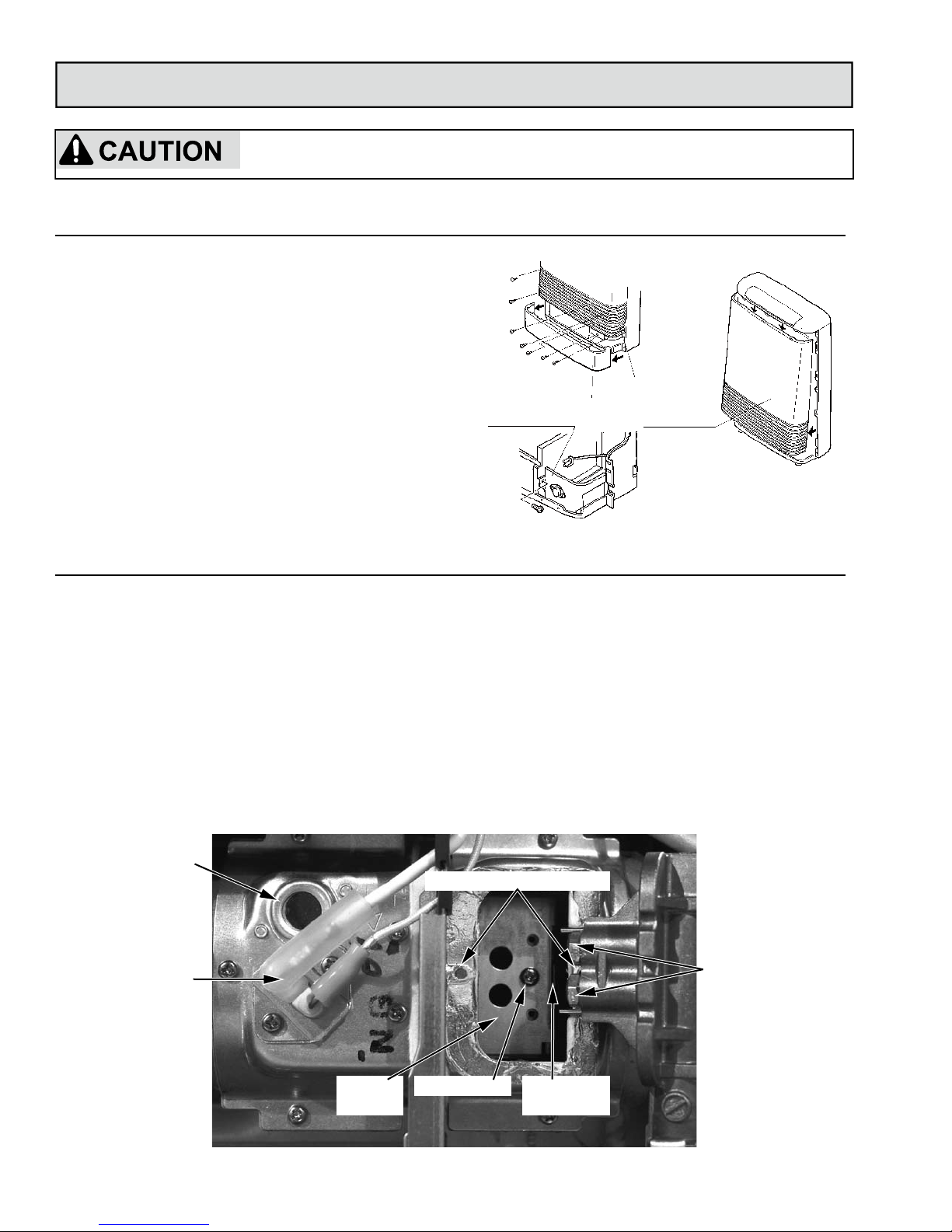
Gain Access
Replace Components
Confirm that the inlet gas pressure is between the minimum and maximum pressures allowed for this appliance.
1. Hold both ends of the bottom cover (Undercover
assembly) and pull toward you to remove the
cover. Cover snaps in place.
2. Remove the 7 screws that hold the front panel and
the louver assembly to remove panel from the unit.
Pull the panel out at the bottom about 4 inches
(100mm) and lift up over clips that hold it in place at
the unit’s top.
3. Remove 1 screw from the bracket with the overheat
switch. Place bracket to the side out of your way.
Refer to the Technical Data and Parts List to ensure to
the correct injectors and dampers are installed.
1. Remove the 2 manifold screws. Rotate the
manifold and connecting tube to access the
injectors.
2.
Replace the 2 injectors with the proper size for the
gas type to be used.
3.
Remove the burner screw from the burner
assembly.
4. Replace the primary and secondary dampers with
the dampers for the gas type to be used. (Pull the
secondary damper straight out using the tab on the
side.)
5. Install the manifold (2 screws) and overheat switch
bracket (1 screw).
6. Confirm that the electrode and leads are installed.
7. Complete the procedure, Adjust Gas Pressure
Settings.
Flame view port
Electrode and leads
Primary
damper
Burner screw
Secondary
damper tab
Injectors
Bracket
Bottom cover
Front panel
Louvers
Rinnai Corporasion RHFE-263FAⅡ Conversion Manual
3
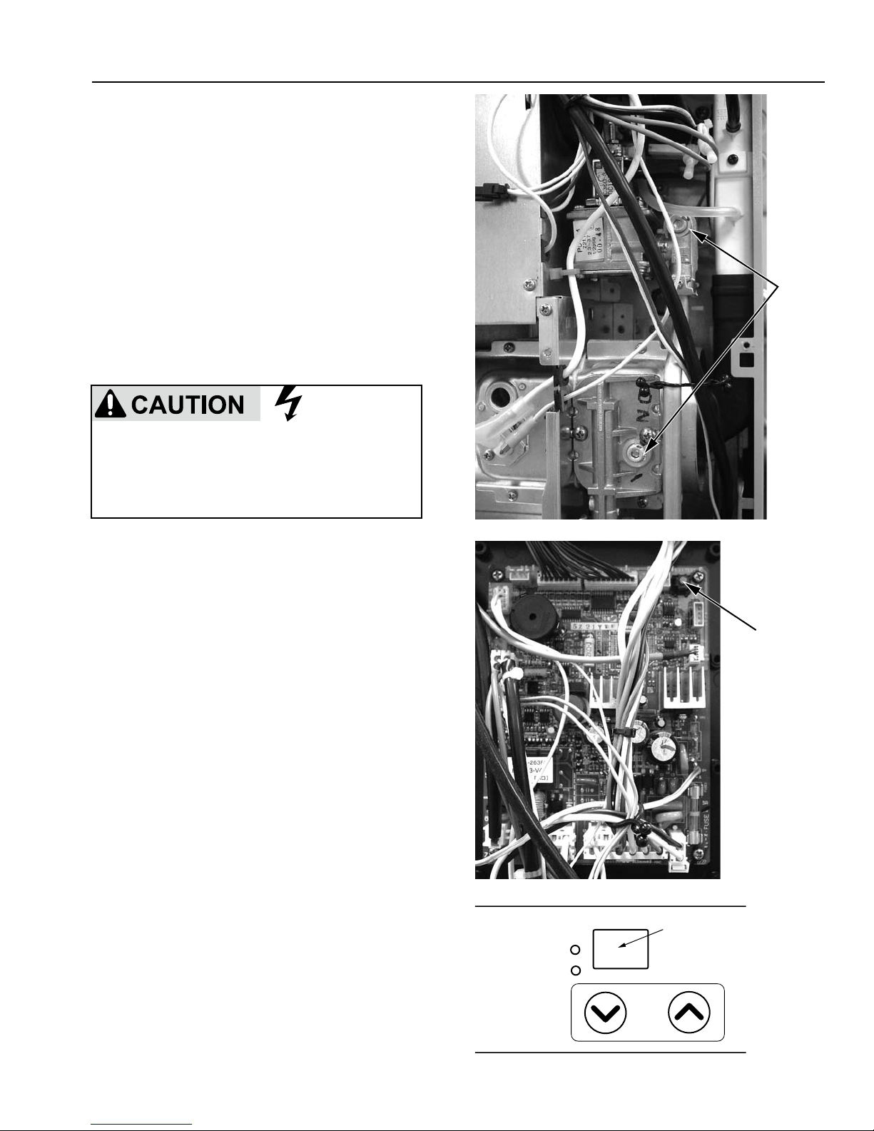
Adjust Gas Pressure Settings
1. Turn off the gas and the power supply.
2. Hold both ends of the bottom cover (undercover
assembly) and pull toward you to remove the
cover. Cover snaps in place.
3. Remove the 7 screws that hold the front panel
and the louver assembly to remove panel from
the unit. Pull the panel out at the bottom about 4
inches (100 mm) and lift up over clips that hold it
in place at the unit’s top.
4. Remove two test point screws (1/8 NPT tap) with
3/16 Allen wrench and attach the manometer to
both test ports. Both ports must be used in order
to measure the differential pressure. Ensure that
the manometer is properly calibrated.
5. Turn on the gas and power supply to the
appliance. With the unit in the Off position, press
the SW1 switch at the top of PC board until it
beeps.
6. Select the correct code on the LED display using
▲ and ▼ buttons:
High altitude is above 2000 ft (610 m).
L1: Propane gas at low (sea level) altitude
L2: Propane gas unit at high altitude
A1: Natural gas at low (sea level) altitude
A2: Natural gas unit at high altitude
7. Press the SW1 test button to record the gas type
code into memory. The LED will display “F1”. If
not shown, use the ▲ and ▼ buttons to obtain
“F1”.
8. Press the SW1 switch to enter this code into
memory.
9. The LED will display the temperature scale. Use
the ▲ and ▼ buttons to select the Fahrenheit or
Celsius scale.
10.Press the SW1 switch to enter the temperature
scale into memory.
Test
points
SW1
Do not touch any other areas on the PC board
besides the “SW” switches while power is supplied
to the appliance. Parts of the PC board are
supplied with 120 volts AC.
SetTemp
RoomTemp
Temp
Control
LED
display
4
Rinnai Corporation RHFE-263FAⅡ Conversion Manual
 Loading...