

Page 1
Rinnai
Cosypanel
Convector Wall Heaters
- ------.- :.. ..
CUSTOMER’S OPERATING
INFORlWXTION AND
INSTALLATION INSTRUCTIONS
This appliance shall be installed in accordance with:
l Manufacturer’s Instructions
l Local Authority Building Codes
Rinnai
l NZS 5261 Installation Code for Gas Burning
GAS SPACE HEATERS
Appliances and Equipment
l Any other relevant Statutory Regulation
This appliance must be installed, serviced and
removed by an authorised person.
Page 2
CUSTOMER’S OPERATING INFORMATION
For trouble free operation please read the following information carefully.
For your convenience the controls are situated on the top right hand side
of the heater.
IMPORTANT
Postinq of Objects
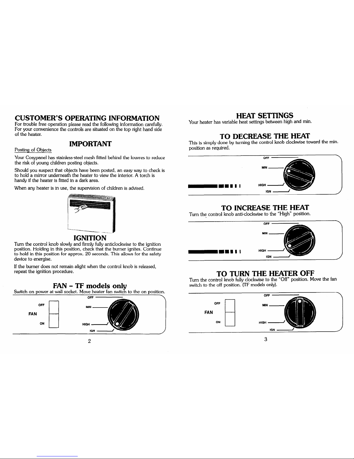
HEAT SETTINGS
Your heater has variable heat settings between high and min.
TO DECREASE THE HEAT
This is simply done by turning the control knob clockwise toward the min.
position as required.
Your Cosypanel has stainless-steel mesh fitted behind the louvres to reduce
the risk of young children posting objects.
Should you suspect that objects have been posted, an easy way to check is
to hold a mirror underneath the heater to view the interior. A torch is
handy if the heater is fitted in a dark area.
When any heater is in use, the supervision of children is advised.
-.-.-_-_
IGNITION
Turn the control knob slowly and firmly fully anticlockwise to the ignition
position. Holding in this position, check that the burner ignites. Continue
to hold in this position for approx. 20 seconds. This allows for the safety
device to energise.
If the burner does not remain alight when the control knob is released,
repeat the ignition procedure.
FAN - TF models only
Switch on power at wall socket. Move heater fan switch to the on position.
OFF
FAN
ON
El
TO INCREASE THE HEAT
Turn the control knob anti-clockwise to the “High” position.
-mm1 1 I
TO TURN THE HEATER OFF
Turn the control knob fully clockwise to the “Off” position. Move the fan
switch to the off position. (TF models only).
2
IGN -
Page 3

CARE OF THE HEATER
Your Cosypanel needs very little maintenance, but the following
information will help you keep it looking good, and working efficiently.
l Unplug unit before cleaning
l All parts of the heater can be cleaned using a soft, damp cloth.
l Do not use solvents to clean any parts.
l Do not spray aerosols in the vicinity of this appliance while it is in
operation.
l Do not place articles on or against this appliance.
l Do not store flammable materials near this appliance.
Service
The internal gas controls are factory set and in normal circumstances will
not require any adjustment in service. If however the unit fails or requires
attention then any approved Rinnai Service Centre or Gas Utility should be
contacted.
NOTE:
Servicing may only be undertaken by an authorised person
Rinnai recommends your Cosypanel is checked and serviced
annually.
INSTALLATION INSTRUCTIONS
Unoack Heater
Preferably undo bottom of carton, place carton correct way up, then lift
carton off the heater. Never lift the heater by its top louvres. Check for
damage. If unit is damaged, contact your Supplier for advice. Before
installing the heater, check unit is labelled for the correct gas type.
Included in Carton
Customer’s instructions.
Wall mounting bracket.
IMPORTANT
1.
The appliance must be installed to the requirements of the local gas
authority.
2.
Do not fix in close proximity to curtains or other combustible
materials.
4
2
2:
7.
8.
9.
For information on gas rate, see data plate on the appliance.
When installing this appliance, ensure that the room is correctly
ventilated.
Do not install in bedroom or bathroom.
This appliance is fitted with variable control and the burner can be
operated at any setting between high and min.
The recommended clearance for installation is 1OOmm from the floor
and 150mm clearance from either of the side panels.
Do not install heater under a shelf, mantlepiece or other projection
within a distance of 800 mm from top of heater.
Do not install heater under a window.
_ .
10. This unit is not designed to be built in.
11. This heater has been designed for convenient wall mounting using the
mounting bracket provided.
NOTE:
MINIMUM ROOM SIZE REQUIREMENT
RSOOT / TF
42 Cu Metres
R501T / TF
29 Cu Metres
In halls, passages and shops where ventilation is greater than normally
obtainable in living rooms, it shall be permissible to increase continuous
heat input to 0.4 MJ/h per cubic metre of enclosed space.
INLET CONNECTION
The inlet to the heater is a 3/8” B.S.P. flare fitting with nut and will fit
1Omm O.D. copper pipe. It is situated 103mm from the right hand end of
the heater and 42mm from the rear of the heater.
INSTALLATION
The rear panel incorporates a combined wall spacer and mounting bracket
extending the full width of the heater. The wall mounting bracket is
supplied taped to the rear of the heater. To maintain 1OOmm clearance
from the floor, the wall bracket should be screwed to the wall at 425mm
from the floor to the centre of the screw holes.
Position the heater on the wall bracket, then secure the heater to the wall
using the bracket provided on the underside of the base panel.
Do not remove the lower rubber wall spacers as these provide an air gap
between the heater and wall.
5
Page 4

Front Panel Removal
The front panel is held in position by four screws, one at either end of the
top louvre and at either end of the underside of the base panel. After
removing all screws ease the panel straight forward clear of the heater.
TF Model Only
An earthed power point is required within 1.5m from the heater.
TESTING PROCEDURE
After clearing .a11 swarf and purging the gas supply to the heater, connect
the gas and check for leakage at connections.
Check Burner Pressure
Turn knob to ignition position to light burner. If burner fails to light,
repeat. The heater is fitted with a flame failure valve included in the gas
valve. Hold valve in the ignition position for 20 seconds and then release.
The heater should continue to operate. If burner goes out check position
of thermocouple in flame and repeat ignition procedure.
Turn control to “Off” position. Remove test point screw and attach
manometer. Light unit in usual way. Leave full on and check pressure.
Reset pressure by adjusting regulator screw if necessary. Regulator is
situated on the side of the gas cock assembly. Check the supply pressure
before making adjustments to unit as the regulator has been factory preset.
Turn control to “Off” position before removing manometer. Replace the
test point screw. Pilot gas rate cannot be adjusted. Turn heater on and off
again a few times to check ignition.
Fan - TF models only
Connect power lead to wall socket and switch on power. Move heater fan
switch to on position and check operation of fan.
Fault Failure Procedure
If you cannot get the heater to work properly, contact Rinnai NZ Ltd, their
nearest Service Centre or Gas Utility.
INSTRUCT CUSTOMER IN USE AND CARE OF THE HEATER
Make sure the customer understands the instructions.
*
3.
4.
SERVICING INSTRUCTIONS
Rinnai recommend your Cosypanel heater is serviced every year.
1. Multifunctional Gas Valve incornoratincr oiezo ianition,
regulator and flame failure safetv device
This valve is designed as a sealed unit and as such it should not be
?
$s.isnan;~d except to replace the flame failure safety device magnetic
2. Thermocounle
The thermocouple may be replaced b
t:
removin
from it’s mounting bracket above the
%
the thermocouple
urner an
releasinq the
connector from the gas valve.
Burner and Injector
Remove the mounting screw from the left hand end of the burner and
slide burner sideways clear of the injector. The injector may now be
unscrewed if required.
Gas Valve
Turn off
from wal P
as supply and disconnect from heater. Remove the heater
and remove screws from the valve mounting bracket, two
from rear panel and one from burner chamber.
Release thermocouple, pilot tube, gas supply pipe and piezo ignition
lead. Lift the valve clear of the heater.
Description
SPECIFICATIONS
-
-
Rinnai Cosypanel R800 / 501T convector wall
heater
Type
-
Description
-
Type
-
Input
-
Gas Control
-
Burner
Test Point Pressure
Gas Inlet
Ignition
Injectors and Gas Rate -
Dimensions
-
Electric Supply -
Fan
-
6
7
Natural convection
Rinnai Cosypanel R800 / 501TF convector wall
heater with fan
Natural or forced convection
R800 NG 8.0 MJ/h R501 NG 5.3 MJ/h
Rinnai multi-functional one touch gas valve
Aeromatic single entry
NG only 1.0 kPa.
Flare fitting to suit 1Omm O.D. copper pipe
Piezo electric
Please see data plate LH side of front panel
Width 540mm, height 390mm, depth 128mm
over mounting bracket
(TF only) 230~ 50Hz A.C. only 0.06 AMP
(TF only) Royal 40mm single speed
Page 5

WIRING DIAGRAM
WIRING DIAGRAM R800TF Cosypanel
Switch
230V
50Hz
2YEARwARRANTY
The Rinnai commitment to quality is backed by our 2 year warranty.
This warranty covers parts and labour for the first year
and parts only for the second year.
This warranty covers domestic use only.
The benefits conferred by the warranty are in addition to all other rights and
remedies in respect of the product you-have purchased, under the terms of the
CONSUMER GUARANTEES ACT.
This warranty does not cover cleaning and normal wear and tear.
Calls of this nature may be chargeable.
RINNAI NEW ZEALAND LTD.
691 MT ALBERT RD, ROYAL OAK
AUCKLAND
p.0. BOX 24-068, AUCKLAND
PHONE: 6254285
FAX: 624-3018
PNo. 6792
Rinnai are continually updating and improving products. Therefore specifications are subject to alterations without notice.
 Loading...