

Page 1
COMMON VENT SYSTEM
Features and Benefits
The Common Venng System provides for longer vent lengths and fewer wall or roof penetraons than
convenonal single-unit venng. CVent provides the necessary components for both combuson air and exhaust
and is made by Ubbink, the same supplier for Rinnai's innovave line of concentric venng. CVent ulizes a CSAcered and tested polypropylene venng material. The various secons are self locking and sealing and can be
pushed together without use of cement or glue. CVent can only be used with Rinnai’s RU98 condensing water
heaters.
For combuson air venng, Rinnai’s Common Venng System ulizes both CVent components and, if necessary for
extended vent runs, schedule 40 PVC.
The CVent Common Venng System can be used with up to 8 water heaters with a 41 foot equivalent vent length,
however if used with 7 or fewer units, the maximum equivalent vent length extends to 100 feet.
Advanced features include a precision-made check valve to prevent exhaust gases from penetrang non-operang
water heaters, avoiding negave impacts on combuson and reliability, as well as joint sockets designed to prevent
condensate from gathering in gaps and degrading gaskets.
The current version of CVent is made of polypropylene (PPtl) and is only for U.S. installaons.
Model Applicability
The common vent system is CSA cered (ANSI Z21.10.3, Gas Water Heaters Standards) for use only with the
Rinnai tankless condensing water heater RU98i (REU-KB3237FFUD-US).
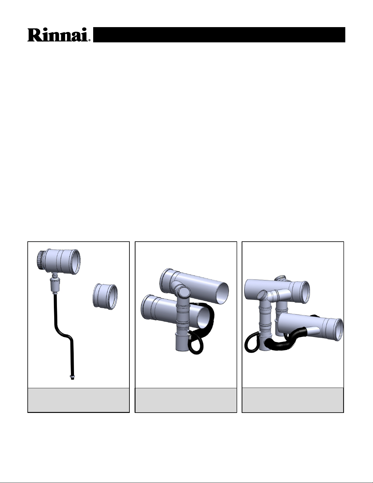
#790006 Cvent Starter Kit (Back-
2Back or InLine)
Rinnai Corporation • 103 International Drive • Peachtree City, GA 30269 • Toll-Free: 1-800-621-9419 • Fax: 678-829-1666 • www.rinnai.us
1 SP-CV-02 (2/13)
#790007 CVent InLine Kit
(Combustion Air & Exhaust)
#790008 CVent Back-2-Back Kit
(Combustion Air & Exhaust)
Page 2
COMMON VENT SYSTEM
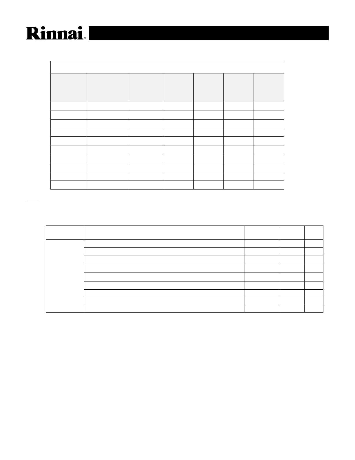
When ordering the CVent components and the Tankless Rack System (TRS) together, please use the following
table and part numbers.
CVent Components for the TRS
Back to
back Add-
on Kit
790008
18” Extension
790020
Part No. Configuration
For No. of
Water
Heaters
CVent
Starter Kit
790005
CVent
InLine Kit
790007
CV8IL4 in-line 4 1 4
CV8IL5 in-line 5 1 5 2
CV8IL6 in-line 6 1 6 2
CV8IL7 in-line 7 1 7 2
CV8IL8 in-line 8 1 8 2
CV8BB4 back-to-back 4 1 2
CV8BB5 back-to-back 5 1 1 2
CV8BB6 back-to-back 6 1 3
CV8BB7 back-to-back 7 1 1 3 2
CV8BB8 back-to-back 8 1 4 2
Key: CV = common vent; 8 = 8 inch diameter; IL/BB= in-line/back-to-back; 4/5/6/7/8 = no. of water heaters
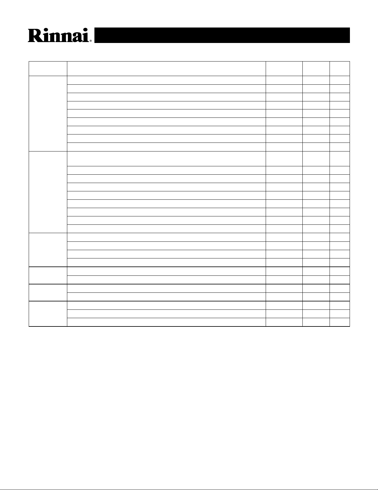
When ordering the CVent exhaust components on their own, please use the following table and part nos.
Length/
Rinnai PN Description Ø Diameter
790005 CVent STARTER KIT, 8-inch For Back-2-Back or InLine
KIT COMPONENTS:
CVENT ENDPIECE (EXHAUST) W/ CLEANOUT & CONDEN-
CVENT COMBUSTION AIR ENDPIECE, D8
CVENT CONDENSATE TRAP (32mm Connection)
CVENT DRAIN HOSE
CVENT DRAIN HOSE CLAMP, L48
UBBINK INSTALLATION INSTRUCTIONS
CENTROCERIN LUBRICANT
8" 1
8” 1
1
48” 1
2
1
1
Other Qty.
Rinnai Corporation • 103 International Drive • Peachtree City, GA 30269 • Toll-Free: 1-800-621-9419 • Fax: 678-829-1666 • www.rinnai.us
2 SP-CV-02 (2/13)
Page 3
COMMON VENT SYSTEM
Parts / Kits
Length/
Rinnai PN Description Ø Diameter
790007
790008
790001
790002 CVent 8-in Flat Roof Flashing
790003 CVent 8-in Pitched Roof Flashing
790004 Cvent 8-in Wall Termination Kit (Combustion Air & Exhaust)
CVent InLine Kit, 8-in Header Kit For InLine Cumbustion Air & Exhaust
KIT COMPONENTS:
CVENT COLLECTOR, 1 CONNECTION, D8 X L20 X D4 (Exhaust)
CVENT ELBOW D4 X 87° WITH CLEANOUT
CVENT EXTENTION, D4 X L18
CVENT APPLIANCE ADAPTER, CHECK VALVE AND HOSE TRAP
CVENT COMBUSTION AIR COLLECTOR, 1 CONNECTION, D8 X L20 X D3
CVENT COMBUSTION AIR FLEX FITTING, D3
CENTROCERIN LUBRICANT
CVent Back-2-Back Kit, 8-in Header Kit For Back-2-Back Combustion Air
and Exhaust
KIT COMPONENTS:
CVENT COLLECTOR, 2 CONNECTION, D8 X L20 X D4 X D4 (Exhaust)
CVENT ELBOW D4 X 87° WITH CLEANOUT
CVENT EXTENSION, D4 X L18
CVENT APPLIANCE ADAPTER WITH CHECK VALVE AND HOSE TRAP
CVENT COLLECTOR, 2 CONNECTION, D8 X L20 X D3 X D3 (Combustion Air)
CVENT COMBUSTION AIR FLEX FITTING, D3
CENTROCERIN LUBRICANT
Cvent 8-in Roof Termination Kit
CVENT 8-IN ROOF TERMINATION
PP-PVC ADAPTER (For Combustion Air PVC Transition)
CENTROCERIN LUBRICANT
CVENT FLAT ROOF FLASHING
CVENT PITCHED ROOF FLASHING, INCLUDING STORM COLLAR
WALL TERMINATION + STAINLESS STEEL GRATE + WALL PLATE (2pc)
CENTROCERIN LUBRICANT
8" X 4” 20" 1
4" 87° 1
4" 18" 1
5” X 4” X 3” 1
8” X 3” 20” 1
3” 24” 1
8" 20" 1
4" 87° 2
4" 18” 2
5” X 4” X 3” 10" 2
8” X 3” 20” 1
3” 24” 2
8" 1
8" 1
1
8" 1
8" 1
8" 3' 1
1
Other Qty.
1
1
Rinnai Corporation • 103 International Drive • Peachtree City, GA 30269 • Toll-Free: 1-800-621-9419 • Fax: 678-829-1666 • www.rinnai.us
3 SP-CV-02 (2/13)
Page 4

Parts / Kits
Rinnai PN Description Ø Diameter Length/Other
COMMON VENT SYSTEM
790020 CVent Extension, D8 x L18 8" 18"
790021 CVent Extension, D8 x L39 8" 39"
790022 CVent Elbow D8 x 45degree (2 in a box) 8" 45°
790023 CVent Elbow D8 x 90degree 8" 87°
790024 CVent 8-in Brackets 8"
790025 Centrocerin lubricant
790035 CVent Extension, D4 x L18 4" 18"
790028 CVent Extension, D4 x L39 4" 39"
790029 CVent Elbow D8 x 90degree Vertical Support 8"
790030 CVent 8-in Chase Cover 8"
790031 CVent 8-in Vent Distancer, stainless steel 8"
790034 CVent 8-in Vent Rain Cap 8"
790032 Inverter Coupling Kit with condensate trap 8"
780037 Combustion Air PVC Adapter Kit 8"
Maximum Equivalent Vent Length
When determining equivalent exhaust and intake vent
lengths add:
• 6 feet for each 90° elbow
• 3 feet for each 45° elbow
• 3 feet for the termination
Number of water
heaters
1 to 7 5 ft 15 ft 100 ft 100 ft
8 5 ft 15 ft 41 ft 41 ft
*Approved exhaust and intake diameter is 8 inches.
Minimum Equivalent Vent Length Maximum Equivalent Vent Length
Exhaust* Intake* Exhaust* Intake*
• Add any vent extension lengths which are added
within the header due to increased spacing of the
water heaters
• Header kits have already been counted and do
not need to be added.
De-Rate
Water heaters using CVent will automatically de-rate according to the table below.
Number of
water
heaters
1 0% 199,000 3.0 0.42 15,200
2 1% 394,000 3.1 0.42 30,400
3 1.5% 588,000 3.1 0.42 45,600
4 2% 780,000 3.1 0.42 60,800
5 2.5% 970,000 3.2 0.45 76,000
6 3% 1,158,000 3.2 0.45 91,200
7 3.5% 1,344,000 3.2 0.45 106,400
8 4% 1,528,000 3.2 0.45 121,600
Rinnai Corporation • 103 International Drive • Peachtree City, GA 30269 • Toll-Free: 1-800-621-9419 • Fax: 678-829-1666 • www.rinnai.us
4 SP-CV-02 (2/13)
Percent
De-rated
Total BTU Rate
Manifold Pressure
Maximum
Rate “W.C.
Minimum
Rate “W.C.
Btu’s at
Minimum Rate
(without MSB)
Btu’s at
Minimum Rate
(with MSB)
15,200
Page 5

790005 CVENT STARTER KIT
8-Inch For Back–2-Back or InLine (Combustion Air & Exhaust)
COMMON VENT SYSTEM
NO QTY DESCRIPTION
1 1
2 1 CVENT COMB AIR ENDPIECE D8
3 1 CVENT CONDENSATE TRAP (32mm Connection)
4 1 CVENT DRAIN HOSE
5 2 CVENT DRAIN HOSE CLAMP
6 1 UBBINK INSTALLATION INSTRUCTION
7 1 CENTROCERIN LUBRICANT
CVENT ENDPIECE (EXHAUST) W/ CLEANOUT & CONDENSATE DRAIN (32mm)
790007 CVENT INLINE KIT
2
1
Qty. 1
Qty. 1
7
5
3
Qty. 1
Qty. 2
Qty. 1
4
8-Inch Header Kit For InLine (Combustion Air & Exhaust)
Qty. 1
1 5
Ø4”
2 4
Qty. 1
3 6
NO QTY DESCRIPTION
1 1 CVENT COLLECTOR, 1 CONNECTION, D8 X L20 X D4 (Exhaust)
2 1 CVENT ELBOW D4 X 87° WITH CLEANOUT
3 1 CVENT EXTENTION, D4 X L18
4 1 CVENT APPLIANCE ADAPTER, CHECK VALVE AND HOSE TRAP
5 1 CVENT COMB. AIR COLLECTOR, 1 CONNECTION, D8 X L20 X D3
6 1 CVENT COMB AIR FLEX FITTING, D3
7 1 CENTROCERIN LUBRICANT
Rinnai Corporation • 103 International Drive • Peachtree City, GA 30269 • Toll-Free: 1-800-621-9419 • Fax: 678-829-1666 • www.rinnai.us
5 SP-CV-02 (2/13)
7
Qty. 1
Ø3”
Qty. 1 Qty. 1
Qty. 1
Page 6

COMMON VENT SYSTEM
790008 CVENT BACK-2-BACK KIT
8-Inch Header Kit For Back-2-Back (Combustion Air & Exhaust)
NO QTY DESCRIPTION
1 1 CVENT COLLECTOR, 2 CONNECTION, D8 X L20
2 2 CVENT ELBOW D4 X 87° WITH CLEANOUT
3 2 CVENT EXTENSION, D4 X L18
4 2
5 1
6 2 CVENT COMB. AIR FLEX FITTING, D3
7 1 CENTROCERIN LUBRICANT
CVENT APPLIANCE ADAPTER WITH CHECK
VALVE AND TRAP
CVENT COMB. AIR COLLECTOR, 2 CONNECTION,
D8 X L20 X D3
Qty. 1
1 5
Qty. 2
Ø4”
Ø4”
2 4
Qty. 2
3 6
7
Qty. 1
Qty. 2
Qty. 2
Ø3”
Ø3”
Rinnai Corporation • 103 International Drive • Peachtree City, GA 30269 • Toll-Free: 1-800-621-9419 • Fax: 678-829-1666 • www.rinnai.us
6 SP-CV-02 (2/13)
Page 7

CVent Terminaon Clearances
Vertical Termination
There should be a minimum of 36 inches between exhaust
terminations in multiple common vent installations.
COMMON VENT SYSTEM
36” MINIMUM INSIDE
EDGE TO INSIDE EDGE
12” OVER MAX.
SNOW LEVEL OR
24” WHICHEVER
IS GREATER
EXHAUST - CVent
INTAKE - PVC
Clearances of Brackets
All supports such as wall brackets on the
external façade or spacer blocks in a
shaft must be assembled in a maximum
distance of 78 in (2 m). Where there is a
bend, additional spacer blocks or wall
brackets can be planned before and after
the bend, depending on the local
situation.
Freestanding Components
Components, which are assembled
freestanding vertical (roof termination)
with a length of more than 59 in (1.5 m),
must, depending on the amount of wind
and snow level expected, be additionally
secured to the building with guys or
braces.
Intake Material
The materials described below can only be used on the combustion air vent. The Ubbink Polypropylene CVent can
be used on both the combustion air and exhaust. Field supplied PVC/CPVC material can only be used on the
combustion air side and MUST NOT be used for the exhaust.
Approval Codes for Installation
Item Description Flue Material United States
PVC Schedule 40 ANSI/ASTM D1785
Plastic Vent and/or combustion air
components
PVC - DWV ANSI/ASTM D2665
CPVC Schedule 40 ANSI/ASTM F441
PVC ANSI/ASTM D2564
Plastic pipe cement and primer
CPVC ANSI/ASTM F493
Options for Combustion Air Vent:
•For extended Combustion Air vent runs, PVC can be used between the Intake Header and Termination.
•Use Combustion Air PVC Adapter Kit (Part #: 780037) when transitioning from the PP intake header to
extended PVC combustion air vent runs. .
Rinnai Corporation • 103 International Drive • Peachtree City, GA 30269 • Toll-Free: 1-800-621-9419 • Fax: 678-829-1666 • www.rinnai.us
7 SP-CV-02 (2/13)
Page 8

COMMON VENT SYSTEM
CVent Termination Clearance
This appliance along with the CVent Common Vent System is certified with the Cvent 8-in Wall
Termination Kit,(790004) mounted in the orientation shown below.
Horizontal Termination
The exhaust and combustion air terminations must
follow these clearances:
[1] 12 inch minimum vertically from bottom of exhaust
termination to top of intake termination.
[2] 12 inch minimum vertically from bottom of
combustion air termination to ground or anticipated
snow line.
[3] From edge of exhaust termination to edge of
combustion air termination:
Minimum of 36 inches
Maximum of 20 feet
[4] 36 inch minimum from multiple exhaust CVents
There should be a minimum of 36 inches between
exhaust terminations in multiple common vent
installations.
Vertically
Combustion
Air Vent
Combustion
Air Vent
Vertically
The vent (exhaust & combustion air) terminations must
be in the same pressure zone and face the same
direction.
NOTE: During colder weather when the exhaust tem-
perature is much hotter than the outside air, the
exhaust fumes condense producing water vapor. As a result a plume of water vapor may be
seen leaving the exhaust.
EXHAUST
VENT
MAXIMUM 20’
MINIMUM 36”
COMBUSTION
AIR
VENT
Rinnai Corporation • 103 International Drive • Peachtree City, GA 30269 • Toll-Free: 1-800-621-9419 • Fax: 678-829-1666 • www.rinnai.us
8 SP-CV-02 (2/13)
 Loading...