

Page 1
FOR YOUR SAFETY.
1. Do not store or use
petrol or other flammable
vapours and liquids in the
vicinity of this or any other
appliance.
2. A gas cylinder not connected
for use must not be stored
in the vicinity of this or any
other appliance.
FOR YOUR SAFETY.
IF YOU SMELL GAS:
1. Shut off gas to the appliance,
if possible.
2. Extinguish any open flame.
3. Open hood.
4. If odour continues,
immediately call your gas
supplier or fire department.
PART NO. P80141002A
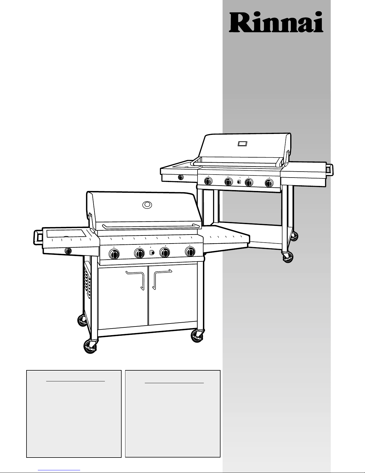
These instructions are a guide
to assembling and using the
Impressor 4 (Australia)
Coastal, Safari (New Zealand)
barbecue.
Please read carefully, and
retain for future reference.
Only to be used outdoors.
Illustration may vary from barbecue
contained in carton.
Customer’s operating &
assembly instructions
Customer’s operating &
assembly instructions
Page 2
GENERAL INFORMAT I O N
2
2
The following minimum clearances from combustible materials
must be maintained when barbecue is in use:
Covered Cookers: top and rear – 450 mm, sides – 250 mm.
Professional Series: top and rear – 800 mm, sides – 250 mm.
Openings at the rear and sides of the appliance provide
air for combustion and must not be obstructed.
CLEARANCES
General Information 2
Safety 3-4
Outdoor Areas 5
Assembly – Covered Cookers (open & cabinet trolley) 6-14
Operation 15-17
Fault Finding 18
Maintenance 19-20
Parts List 21-23
Contacts 27-28
TABLE OF CONTENTS
Height – hood closed 1215 mm, hood open 1515 mm
Width – 1740 mm
Depth – hood closed 655 mm, hood open 725 mm
OVERALL DIMENSIONS
Appliance specifications can be found on the data label attached
to the side panel of the barbecue body.
SPECIFICATIONS
This appliance is certified to AS 4557 by the Australian Gas
Association – depending on model: Certificate No. 6442.
Barbecues must be used in accordance with the installation
requirements of your local gas supply authority, and the
appropriate installation standard AS5601.
GAS INSTALLATION CODES
Barbecues for use with bottled gas are labelled ‘Universal LPG’
or ‘Propane’. Barbecues for use with natural gas are labelled
‘Natural Gas’ and must be installed by an authorised person.
Check the gas type sticker attached to the barbecue. Check that
the label matches the gas type to be used.
Your barbecue is preset at the factory to operate on bottled
gas only, unless specified otherwise.
The regulator and hose assembly supplied with the barbecue
are suitable for use with bottled gas.
This regulator is adjusted to have an outlet pressure of
2.75 kPa for connection to a gas cylinder only. The regulator
and hose assembly supplied with the appliance must be used.
Replacement regulator and hose assemblies must be those
specified by the appliance manufacturer.
When connecting the hose and regulator assembly to the
gas cylinder, take care to avoid unnecessary twisting of the
flexible hose. Also, take care to avoid a loose connection with
the gas cylinder. After the assembly has been secured, turn on
the gas and check for leaks by brushing a liquid detergent and
water solution over all visible and accessible gas line connections.
Include checking those connections which were made by your
supplier. The presence of bubbles will indicate a gas escape.
DO NOT TEST FOR GAS ESCAPES WITH AN OPEN FLAME.
If you are unable to correct the leak by tightening the
connections, turn off the gas and contact your place of purchase
immediately.
Always ensure the appliance is kept away from flammable
materials and the gas cylinder clear of any heat source. When
changing over from an empty gas cylinder to a full one, make
sure this procedure is carried out in a flame free atmosphere.
Inspect the gas hose assembly when exchanging the gas
cylinder, or at least once a year, whichever is more frequent. If the
‘O-Ring’ or PVC hose is cracked, cut, abraded or damaged in any
way, the appliance must not be operated. The complete assembly
must be replaced if damaged and when statutory conditions
require it. Contact your place of purchase if uncertain.
HOSE AND REGULATOR SAFETY
NEVER OPERATE THIS BARBECUE
WITHOUT A REGULATOR.
!
• FAILURE TO COMPLY WITH THESE
INSTRUCTIONS COULD RESULT IN A FIRE
OR EXPLOSION WHICH COULD CAUSE
SERIOUS BODILY INJURY, DEATH OR
PROPERTY DAMAGE.
• ACCESSIBLE PARTS MAY BE VERY HOT.
• KEEP YOUNG CHILDREN AWAY.
• ANY MODIFICATION OF THIS
APPLIANCE MAY BE DANGEROUS.
• DO NOT MOVE THIS APPLIANCE
DURING USE.
• TURN OFF THE GAS SUPPLY AT THE GAS
CYLINDER AFTER USE.
• READ THE INSTRUCTIONS BEFORE USING
THE APPLIANCE.
• PARTS SEALED BY THE MANUFACTURER
MUST NOT BE ALTERED IN ANY WAY.
• THIS BARBECUE IS ONLY TO BE
USED OUTDOORS.
!
Purchased from
Date purchased
Serial No.
NOTE: Sales docket must be kept as proof of purchase date.
FOR CUSTOMER REFERENCE
(Record and file in a safe place)
Page 3
SAFETY
3
3
FOR YOUR SAFETY:
• DO NOT STORE OR USE PETROL OR
OTHER FLAMMABLE VAPOURS AND
LIQUIDS IN THE VICINITY OF THIS OR
ANY OTHER APPLIANCE.
• DO NOT STORE EMPTY OR FULL SPARE
GAS CYLINDERS UNDER OR NEAR THIS
OR ANY OTHER APPLIANCE.
• KEEP THE GAS HOSE AWAY FROM HOT
SURFACES. PROTECT GAS HOSE FROM
DRIPPING GREASE.
AVOID UNNECESSARY TWISTING OF
HOSE. VISUALLY INSPECT HOSE PRIOR TO
EACH USE FOR CUTS, CRACKS, EXCESSIVE
WEAR OR OTHER DAMAGE. REPLACE
HOSE, IF NECESSARY.
• NEVER TEST FOR GAS LEAKS WITH A LIT
MATCH OR OPEN FLAME.
• NEVER LIGHT BARBECUE WITH LID ON
OR HOOD CLOSED.
• NEVER LEAN OVER COOKING
SURFACE WHILE LIGHTING BARBECUE.
• USE GOOD QUALITY INSULATED OVEN
MITTS WHEN OPERATING BARBECUE.
• NEVER ALTER OR MODIFY THE
REGULATOR OR GAS SUPPLY ASSEMBLY.
• THIS BARBECUE MUST NOT BE USED
INDOORS.
!
DANGER – IF YOU SMELL OR HEAR
THE HISS OF ESCAPING GAS FROM
THE GAS CYLINDER:
• KEEP CLEAR OF THE GAS CYLINDER.
• TURN ALL CONTROLS ON THE BARBECUE
TO ‘OFF’, IF SAFE TO DO SO.
•
EXTINGUISH ANY OPEN FLAME.
•
REMOVE LID OR OPEN HOOD.
•
IF ODOUR CONTINUES, IMMEDIATELY
CALL YOUR GAS SUPPLIER OR FIRE
BRIGADE.
!
READ CAREFULLY BEFORE
ASSEMBLING AND OPERATING
YOUR BARBECUE.
!
NEVER CONNECT AN UNREGULATED
GAS CYLINDER TO YOUR BARBECUE.
!
• NEVER STORE YOUR
GAS CYLINDER INDOORS.
• FOR STORAGE AND CYLINDER
EXCHANGE, DISCONNECT HOSE AT THE
CYLINDER ONLY –
DO NOT DISCONNECT HOSE FROM
THE APPLIANCE
!
DO NOT use your barbecue in garages, porches, breezeways, sheds
or other enclosed areas. Your barbecue is to be used OUTDOORS
ONLY. Refer to page 5. The barbecue is not intended to be installed
in or used on recreational vehicles and/or boats and should not be
placed adjacent to or under any surface that will burn. Do not
obstruct the flow of combustion and ventilation air around the
barbecue housing while in use.
LOCATION OF YOUR BARBECUE
If you store your barbecue indoors, ALWAYS disconnect and
remove gas cylinder FIRST, and store gas cylinder safely outside.
Gas cylinders must be stored outdoors in a well ventilated area
out of reach of children, and must not be stored in a building,
garage or any other enclosed area.
This is a low pressure barbecue and must only be used with the
hose and regulator supplied.
Your barbecue is designed for use with a 9 kg gas cylinder.
Ensure gas cylinder conforms to Australian Standard AS2469
and is less than 10 years old, or re-certified if older than 10
years.
DO NOT CONNECT YOUR BARBECUE TO A GAS
CYLINDER LESS THAN OR EXCEEDING 9 kg CAPACITY.
GAS CYLINDER USE & SAFETY
SERVICING
ANY OF THE FOLLOWING SIGNS MAY
INDICATE THAT THE APPLIANCE IS NOT
OPERATING PROPERLY AND MAY NEED
SERVICING:
• EXCESSIVE YELLOW FLAME
• IRREGULAR SIZE OF FLAME
ACROSS BURNER
•‘POPPING’ OF FLAME
• SOOTING
• ABNORMAL NOISE(S)
• HISSING SOUND
NOTE:
Before requesting service,
please refer to page 28
‘If Barbecue Fails to Operate Properly’
!
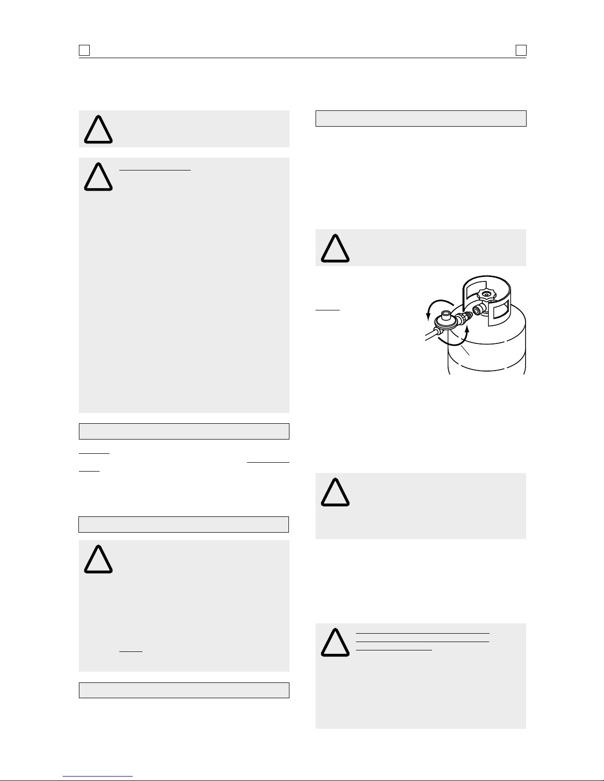
NOTE: The connection to
the gas cylinder is an
‘ANTI-CLOCKWISE’ connection. Ensure the connection is
Ensure the connection is
tightened firmly. Normally only
1-1
1
/2 threads of the hose assembly
connection should remain visible.
The gas cylinder should be filled by a reputable gas dealer, or
exchanged at a reputable gas cyl inder e xc hange outlet. Gas
cylinders should be visually inspected and re-qualified
periodically.
Always keep gas cylinder in an upright position. Always
close the cylinder valve when the barbecue is not in use.
Do not subject the gas cylinder to excessive heat.
Direction for
tightening
Keep children away from barbecue during use and until
barbecue has cooled after you are finished. Do not allow
children to operate barbecue or to swing on handle.
PROTECT CHILDREN
Page 4
SAFETY
4
4
NEVER CHECK FOR LEAKS WITH
A FLAME
!
IF YOU HAVE A GAS LEAK YOU
CANNOT RECTIFY, TURN OFF THE GAS
AT THE SOURCE. CONTACT THE
MANUFACTURER
!
ALWAYS CHECK FOR GAS LEAKS
EACH TIME YOU USE YOUR BARBECUE
!
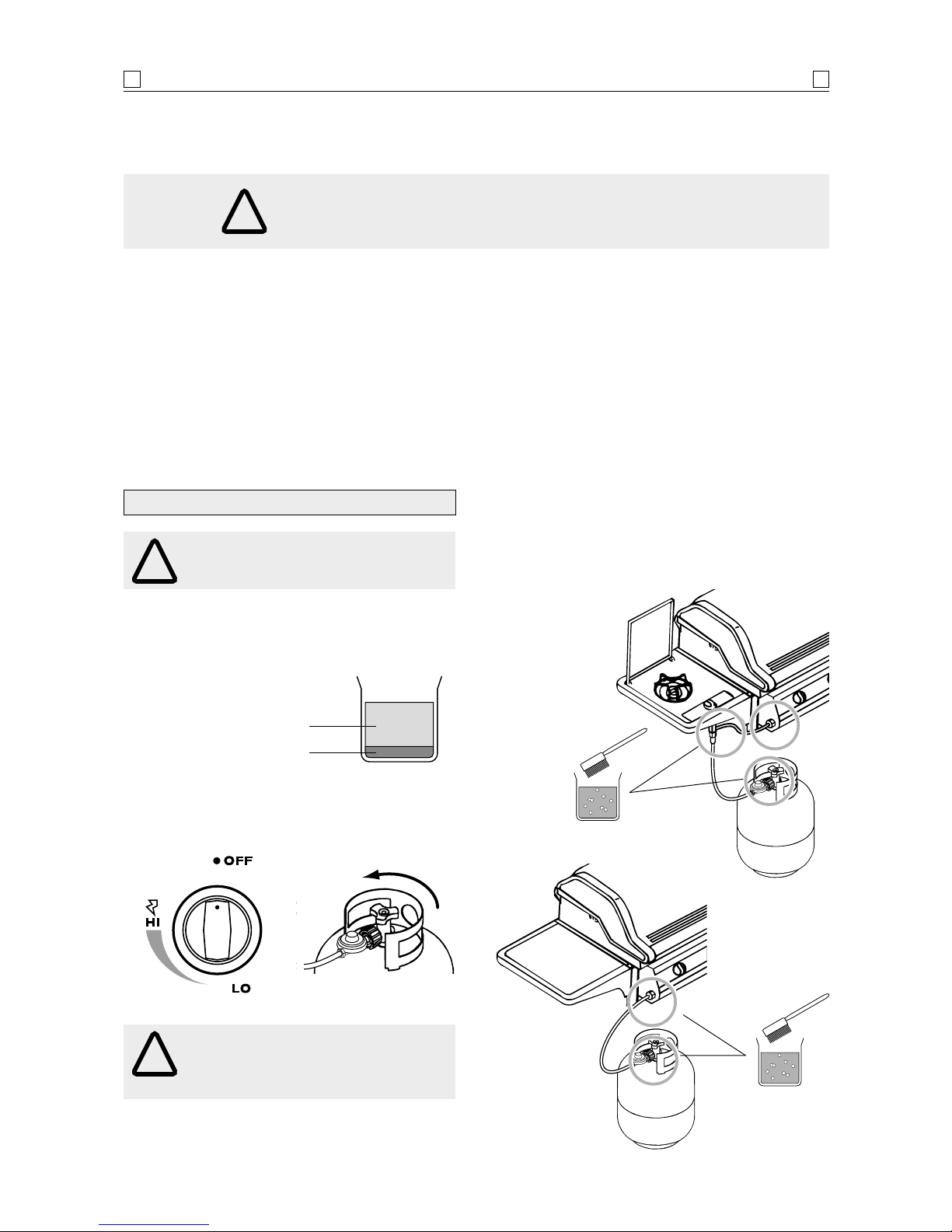
1. Make liquid detergent solution by mixing one (1)
part liquid detergent and four (4) parts water.
2. Turn burner control(s) to ‘OFF’, then turn on gas at
source.
CHECKING FOR GAS LEAKS
You should follow this procedure after any of the following:
• Not having used the barbecue for an extended period of time,
• Initial assembly of barbecue,
• Any disconnection and reconnection of hose assembly,
• Changing gas cylinder,
• Upon re-connecting gas cylinder after it has been disconnected for storage.
4 parts water
Open
1 part liquid
detergent
3. Apply the liquid detergent solution to all visible and
accessible gas connections, including the connection
to the gas cylinder. Bubbles will appear in the liquid
detergent solution if connections are not properly
sealed. Tighten or rectify as necessary.
Page 5
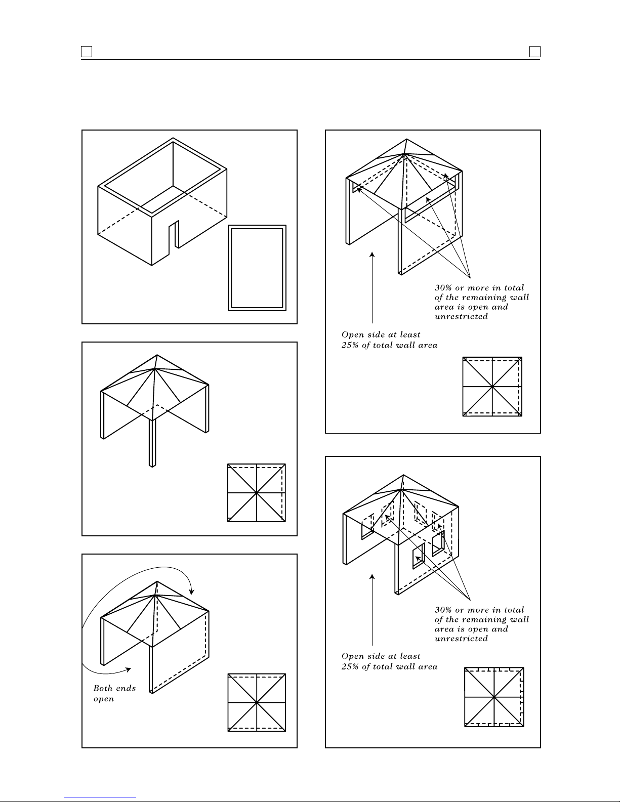
OUTDOOR AREAS
5
5
The following diagrams are examples of outdoor areas. These same principles apply to canopy or shaded cloth areas.
Page 6
ASSEMBLY
6
6
Description Cabinet trolley Open trolley
quantity quantity
Support bracket 2 2
Trolley legs – LH 1 set 2
Trolley legs – RH 1 set 2
Bottom shelf 1 1
Rear panel 1 Side panel 2 Gas cylinder hook 1 1
Gas cylinder support 1 1
Door bracket 1 Door 2 Door handle 2 Shelf bracket 4 4
Side shelf 1 1
Side burner 1 1
Side shelf handle 2 2
Barbecue body 1 1
Grease tray 1 1
Grease receptacle 1 1
Hot plate 1 1
Grill plate 1 1
Flame tamer 2 2
Warming rack – fixed 11
Hardware pack 1 1
Castors 4 4
CONTENTS LIST
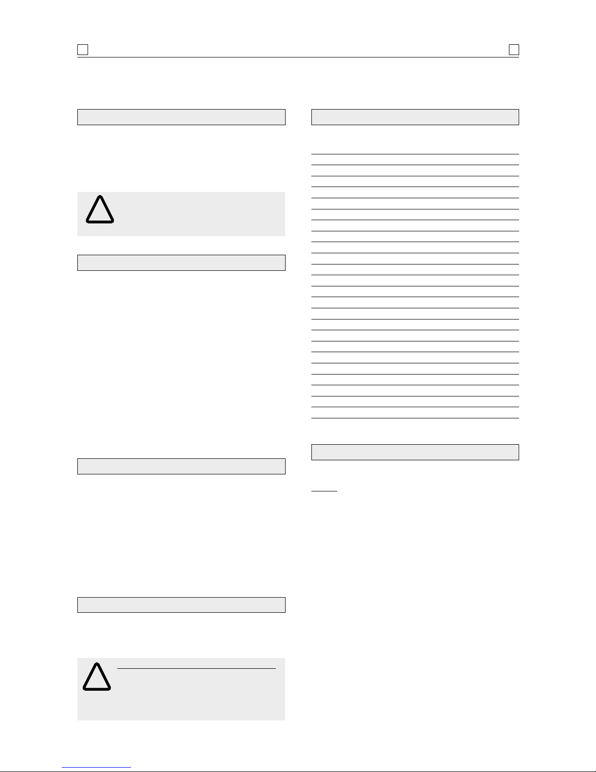
Unpack and remove all protective packaging.
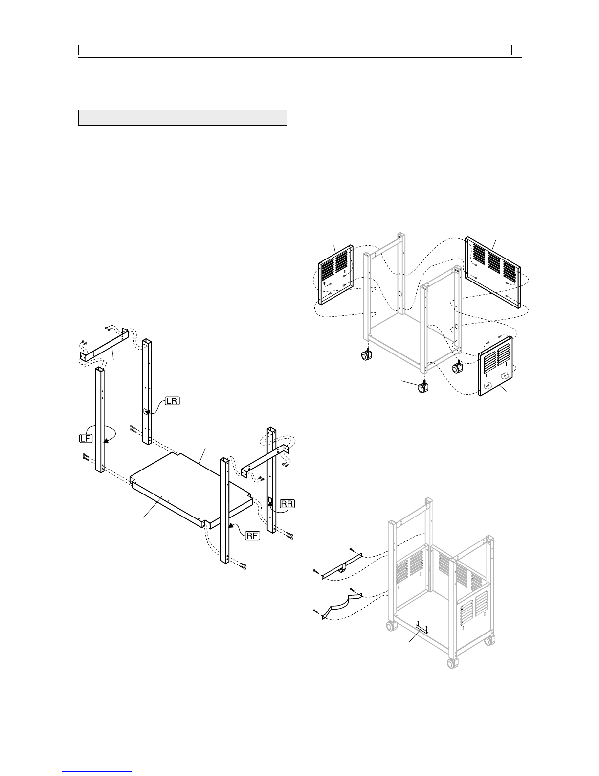
NOTE: The labels on the trolley legs indicate their
assembly position to the bottom shelf. LF=Left Front,
LR=Left Rear, RF=Right Front, and RR=Right Rear.
Labels should face inward toward each other when
correctly assembled. Remaining components cannot be
assembled if leg positions are incorrect.
1. Locate the four (4) trolley legs to the indicated
corners of the bottom shelf using eight (8)
1
/4" x
21/2" Phillips-head screws provided. Do not fully
tighten screws.
Refer to diagram 1.
2. Locate barbecue body support brackets, facing
inward, to trolley legs on both sides using eight (8)
1
/4" x 1/2" Phillips-head screws. Fully tighten.
Refer to diagram 1.
COASTAL
Standard Phillips-head screwdriver.
Adjustable spanner
(open end shifter).
TOOLS YOU WILL NEED
1. Flatten cardboard packaging and use this as a
protective work surface to assemble upon.
2. Do not tighten screws and nuts, unless directed,
until trolley is fully assembled.
3. Pre-screwing of connection points for securing the
side shelves will assist in securing shelves smoothly.
4. Gas cylinder support bracket should always be
assembled over wheel-side of trolley.
ASSEMBLY TIPS
Before attempting to assemble your barbecue, check
that all the necessary parts have been included using the
contents list. Inspect barbecue and trolley parts as you
proceed.
Contact your place of purchase for assistance
regarding replacement of any damaged or missing parts.
Do not assemble or operate a barbecue that
appears damaged.
Check that the barbecue supplied is correct for the
gas type being used. There is a label on the side panel
of the barbecue above the gas connection. Barbecues for
use with gas cylinders are labelled
‘Universal LPG’ or
‘Propane’. Barbecues for use with natural gas are
labelled
‘Natural Gas’.
CHECK BARBECUE FOR ANY DAMAGE
PARTS SUPPLIED SEALED IN THE
CARTON OR BY YOUR PLACE OF
PURCHASE MUST NOT BE ALTERED IN
ANY WAY.
!
BARBECUES ON TROLLEYS ARE HEAVY:
TO AVOID POSSIBLE INJURY CAUSED
WHEN MOVING THE BARBECUE AND
TROLLEY, THE BARBECUE SHOULD BE
PUSHED FORWARD, AND NOT PULLED
FROM BEHIND.
!
While it is possible for one person to assemble the
barbecue, we recommend asking for the assistance of
another person when manoeuvring some of the larger
or heavier pieces.
GENERAL
Page 7
Shelf bracket, flat
side facing outward
Orifice
support bracket
Diagram 2.
Diagram 1.
Support
bracket
Bottom
shelf
Match lighting
stick and chain
Diagram 3.
Side burner
frame
Side burner
lid
Side
shelf
Align
holes
ASSEMBLY
7
7
Cylinder
gas support
Cylinder
hook
3. Screw the four (4) castors into the castor mounting
blocks in the bottom of each trolley leg. Turn the
threaded castor stem by hand, clockwise until it
stops. Fully tighten with the spanner provided.
Refer to diagram 2.
4. Attach the four (4) side shelf brackets to the tops of
the trolley legs using eight (8) of the
1
/4"x 1/2"
Phillips-head screws. Be sure the flat side of each
bracket faces outward. Secure firmly.
Refer to diagram 2.
5. Place the side shelves over the brackets and cross
braces with the wider-spaced shelf holes to the
outside
(shelf with panel on right side). Be sure the
inside shelf holes align with the support bracket
holes.
Refer to diagram 3.
6. To connect the side shelf handle, remove the bolt
and washer from one side of the handle
(cap
remains with handle).
From beneath shelf, place
washer onto bolt and insert bolt through end of
shelf bracket, side shelf, and into handle. Leave
bolt loose until other side of handle is attached,
then fully tighten both sides. Repeat for side burner
shelf.
Install the match lighting stick and chain on the
right rear leg using M4 x 10 mm self-tapping
Phillips-head screw.
Refer to diagram 3.
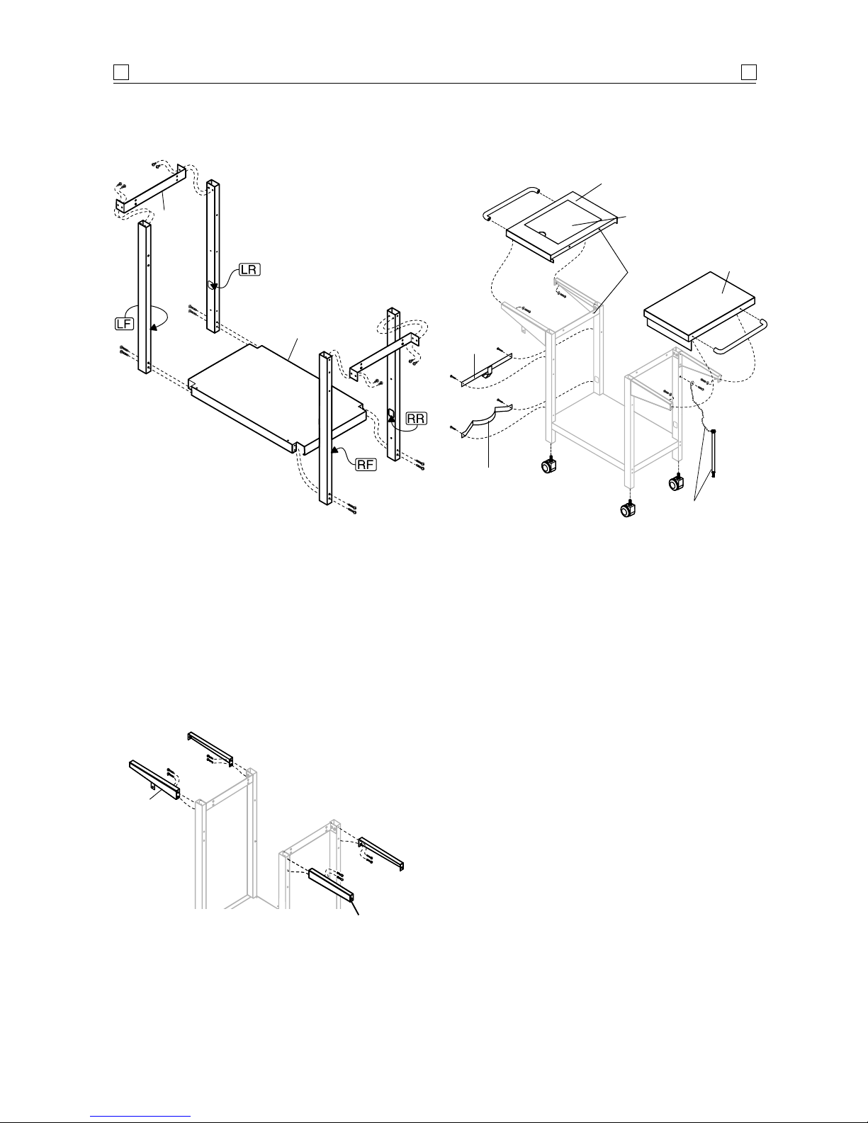
Page 8
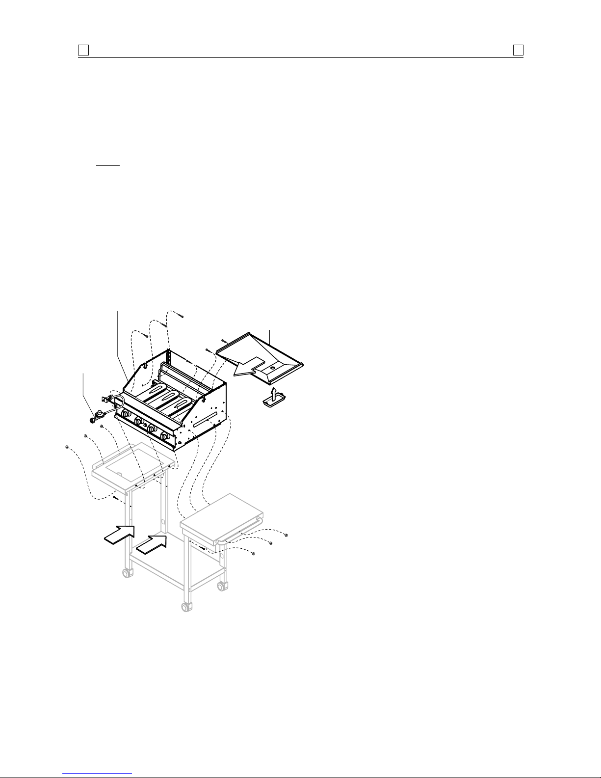
To reduce the weight of the barbecue body,
open the barbecue hood and remove the packed
components. This step requires two (2) people to
lift and position the barbecue body onto the trolley.
7.
HINT: Slide barbecue body into trolley from the
front. Use care to avoid scratching tops of side
shelves. Align the three (3) holes beneath the hang
ledge on each side of the barbecue body with the
three (3) holes in the side shelf and barbecue body
support bracket on the trolley. Open the barbecue
hood and insert six (6) of the
1
/4 x 1/2" Phillipshead screws as shown, and secure beneath the side
shelves, with
1
/4" nuts. Do not fully tighten.
8. Slide the grease draining tray into the back of the
barbecue body. Place the grease receptacle into the
notches in the bottom of the tray.
Refer to diagram 5.
9. Attach barbecue body to all trolley legs using four
(4) of the
1
/4 x 21/2" Phillips-head screws and 1/4"
locknuts.
Refer to diagram 5.
10. Fully tighten all screws.
11.
Go to page 12 ‘Assembling The Side Burner’.
Gas hose
and
regulator
assembly
Grease
receptacle
Grease
draining
tray
Hang
ledges
rest on
shelves
ASSEMBLY
8
8
Diagram 5.
Barbecue
body
Shown without hood
for assembly clarity
Page 9
Unpack and remove all protective packaging.
NOTE: The labels on the trolley legs indicate their
assembly position to the bottom shelf. LF=Left Front,
LR=Left Rear, RF=Right Front, and RR=Right Rear.
Labels should face inward toward each other when
correctly assembled. Remaining components cannot be
assembled if leg positions are incorrect.
2. Locate the four (4) trolley legs to the indicated corners
of the bottom shelf using eight (8)
1
/4" x 21/2"
Phillips-head screws. Do not fully tighten screws.
Ensure the door stopper mountings are facing the
front.
Refer to diagram 1.
3. Locate barbecue body support brackets, facing
inward, to trolley legs on both sides using eight (8)
1
/4" x 1/2" Phillips-head screws. Fully tighten.
Refer to diagram 1.
SAFARI
Diagram 1.
Support
bracket
Bottom
shelf
Door stopper mountings
ASSEMBLY
9
9
4. Screw the four (4) castors into the castor mounting
blocks in the bottom of each trolley leg. Turn the
threaded castor stem by hand, clockwise until it
stops. Fully tighten with the spanner provided.
Refer to diagram 2.
5. Install the two side panels and one rear panel to the
trolley by using four (4) of the
3
/16"x 1/2" Phillipshead screws on each panel. Leave rear panel
screws loose.
Refer to diagram 2.
6. Attach the door stopper to the bottom shelf, with
the flange facing the front, using two (2)
3
/16"x3/8"
Phillips-head screws. Attach the gas cylinder hook
and support to the left side trolley legs using four
(4)
1
/4"x1/2" Phillips-head screws. Fully tighten.
Refer to diagram 3.
Door
stopper
Castor
Rear
panel
Side
panel
Side
panel
Diagram 2.
Diagram 3.
Page 10

7. Attach the door bracket to the lower holes in the
front legs with the end tabs pointing upward and
the flange to the rear, pointing downward. Use
two (2) of the
1
/4"x1/2" Phillips-head screws. Do
not fully tighten.
Refer to diagram 4.
8. Place doors into the hinge holes of the bottom shelf
and door bracket. Push door bracket down until
doors are secure and can open and close freely. Do
not fully tighten door bracket screws.
Refer to diagram 4.
9. Remove protective film from doors. Install door
handles to doors using four (4) of the
3
/16"x3/8"
Phillips-head screws and washers.
Refer to diagram 4.
ASSEMBLY
10
10
Lower
hole
Hinge hole
Hinge
Remove
film
Handle
Door
Door
bracket
Screw with
washer
Diagram 4.
10. Attach the four (4) side shelf brackets to the tops of
the trolley legs using eight (8)
1
/4"x1/2" Phillipshead screws. Be sure the flat side of each bracket
faces outward to the front and rear. Fully tighten.
Refer to diagram 5.
Shelf bracket,
flat side facing
outward
Orifice
support
bracket
Diagram 5.
11. Place the side shelves over the brackets and cross
braces with the wider-spaced shelf holes to the
outside
(shelf with panel on right side). Be sure the
inside shelf holes align with the support bracket
Refer to diagram 6.
12. To install the side shelf handle, remove the bolt
and washer from one side of the handle
(cap remains
with handle).
From beneath shelf, place washer onto
bolt and insert bolt through end of shelf bracket,
side shelf, and into handle. Leave bolt loose until
other side of handle is attached, then fully tighten
both sides. Repeat for side burner shelf.
Install the match lighting stick and chain on the
right rear leg using M4 x 10 mm self-tapping
Phillips-head screw.
Refer to diagram 6.
Match lighting
stick and chain
Diagram 6.
Side burner
frame
Side burner
lid
Side
shelf
Align
holes
Page 11

14. Fully tighten all leg screws, rear panel screws, door
bracket screws, and barbecue body screws.
15. From the back of the trolley, slide the grease
draining tray into the barbecue body. Place the
grease receptacle into the notches on the bottom of
the tray.
Refer to diagram 9.
16. Attach barbecue body to all trolley legs using four
(4)
1
/4 x 21/2" Phillips-head screws and nuts.
17. Fully tighten all screws
Attach
barbecue
body to
all 4 legs
Grease
draining
tray
Grease
receptacle
Diagram 9.
GAS HOSES ARE FACTORY FITTED AND
LEAK TESTED – DO NOT DISCONNECT.
!
Gas hose and
regulator
assembly
13. To reduce the weight of the barbecue body,
open the barbecue hood and remove the packed
components. This step requires two (2) people to
lift and position the barbecue body onto the trolley.
HINT: Slide barbecue body into trolley from the
front. Use care to avoid scratching tops of side
shelves. Align the three (3) holes beneath the hang
ledge on each side of the barbecue body with the
three (3) holes in the side shelf and barbecue body
support bracket on the trolley. Open the barbecue
hood and insert six (6) of the
1
/4" x 1/2" Phillipshead screws as shown, and secure beneath the side
shelves, with
1
/4" nuts. Do not fully tighten.
Refer to diagram 8.
ASSEMBLY
11
11
Hang
ledges
rest on
shelves
Diagram 8.
Shown without hood
for assembly clarity
Barbecue
body
Page 12

5 mm spark gap Inside nut
Spark electrode tip
ASSEMBLY
12
12
Orifice support
bracket
Orifice
support
bracket
Valve
orifice
Side
burner
Valve
orifice
Side burner
opening
Front
panel
Ignition wire from
barbecue body
Ensure the folded
edge is resting on
top of the bottom
fold of the side shelf
Ignition wire
connection
Control
knob
Control
knob seat
2. Attach the front panel with the valve stem going
through the front opening. Ensure the folded edge
is resting on top of the bottom fold of the side shelf.
Secure the valve and control knob seat to front
panel with screws. Connect the ignition wire from
barbecue body to the ignition wire of electrode
assembly.
1. Insert the valve orifice through the orifice support
bracket on the left front shelf bracket and into the
side burner opening.
INSTALLING THE SIDE BURNER
1. Unscrew the igniter cap located on the control
panel and remove the contact and spring from the
igniter slot.
2. Place the supplied AA battery into the igniter slot
with the positive pole facing toward you.
3. Place the spring
with contact over
the battery. Screw
the igniter cap back
onto the control
panel.
IGNITION BATTERY INSTALLATION
Before placing the cooking components into your
barbecue body, ensure that the spark electrode tip is
properly positioned within each gas collector box
(a
stainless steel mechanism found at side of burner
. The
easiest way to ensure this is to perform the following
electrode check:
1. Be sure all control knobs are set to
‘OFF’. Open the
barbecue hood.
NEVER put your face inside the
barbecue body.
2. Push the piezo igniter or continuous ignition button
and look down at the gas collector box. If a spark
is present the electrode tips are properly positioned.
3. After correct spark gap has been verified and there
is still no spark evident, check that the ignition lead
is firmly attached to the spark electrode and ignition
source.
4. If no spark is seen, then the spark gap shown below
may need to be adjusted as follows:
The gap between the spark electrode tip and spark
receiver should be approximately 5 mm.
If the gap is wider the 5 mm use a pair of long nose
pliers and gently bend the end of the gas collector
box in or out to adjust to the correct gap.
MAIN BURNER ELECTRODE CHECK
Burner tubeOrifice
Gas
valve
Gas collector box Screw
Continuous igniter
Spark electrode Burner port
Foot
Burner control
Burner
AA
battery
Spring
Igniter
cap
Contact
Page 13

ASSEMBLY
13
13
TEST FOR LEAKS WITH A LIQUID
DETERGENT SOLUTION, NEVER WITH
AN OPEN FLAME (Refer to page 4)
!
CONNECTING TO GAS SOURCE
1. Hang filled gas cylinder on the cylinder hook.
2. Attach cylinder connection
device of regulator and hose
assembly to cylinder
valve outlet.
Tighten firmly.
3. Open the gas
cylinder valve fully
to allow gas to flow.
4. Leak test all accessible
connections thoroughly,
including the connection to the
gas cylinder, using a liquid detergent water
solution prior to lighting the barbecue.
Refer to ‘Safety’ information, pages 3 and 4.
5. If a leak is found, turn gas cylinder valve off and do
not use barbecue until repairs or replacement can
be made.
DISCONNECTING FROM GAS SOURCE
1. Turn the burner control ‘OFF’.
2. Turn the gas cylinder valve off fully.
3.
Detach the regulator assembly from gas cylinder
valve. Protect the connection end of the regulator
from damage.
This barbecue is also certified for use on natural gas.
Contact the manufacturer or place of purchase for advice
in relation to using your barbecue on natural gas.
Barbecues for use on natural gas must be installed
by an authorised person.
NATURAL GAS INSTALLATION
Set the side burner and the three left side main burners
to operate on maximum gas rate ‘HI’. Set the operating
pressure to 0.87 kPa at the far right main burner injector.
SETTING TEST POINT PRESSURE
• DISCONNECT AND REMOVE GAS
CYLINDER WHEN MANOEUVRING THE
BARBECUE OVER UNEVEN SURFACES
OR CARRYING UP AND DOWN STAIRS.
• IF THIS INFORMATION IS NOT
FOLLOWED EXACTLY, A FIRE
CAUSING DEATH OR SERIOUS INJURY
MAY OCCUR!
• DO NOT STORE A SPARE GAS
CYLINDER UNDER OR NEAR THIS
APPLIANCE.
• THIS BARBECUE IS ONLY TO BE
USED OUTDOORS.
!
Direction for
tightening
Familiarise yourself with the general information and
safety guidelines located at the front of this booklet.
Check to see that gas cylinder is filled and that end of
each burner tube is properly located over each valve
orifice. Set burner controls to
‘OFF’ position.
ENSURING BURNER CONTROLS ARE OFF
IMPORTANT: Before connecting and disconnecting
barbecue to gas source, ensure burner controls are in
‘OFF’ position.
NOTE:
The ‘OFF’ position on the control panel is
identified by either a small black dot / a short vertical
black line / or the word ‘OFF’.
When the marking, or the word ‘OFF’ printed on
the control knob, aligns with the printed marking on the
control panel, then the burner is in the fully off position.
CAUTION:
When the appliance is not in use, the gas
must be turned off at the gas cylinder
.
CONNECTING TO, AND DISCONNECTING
FROM GAS SOURCE
Page 14

ASSEMBLY
14
14
Before first use:
1. Please read ‘
Safety’, ‘Lighting’ and ‘Operating’
instructions carefully.
2. Check and ensure the gas cylinder is full.
3. Ensure all connections are securely tightened. Check
for gas leaks.
Refer to page 4.
At the beginning of each barbecue season:
1. Check gas valve orifices, burner tubes and burner
ports for any obstructions.
eg. spiders, webs, insects.
NOTE: The barbecue cannot be operated using two (2)
hot plates.
NOW YOUR BARBECUE IS READY TO USE
Check and ensure that each burner is properly located
over each orifice prior to installing the flame tamer.
1. The flame tamer is designed to reduce flaring.
Place the flame tamers on the lower edge above
burners. Flame tamers must always be located
under the grill plate.
2. Position the cooking plates
as shown below.
3. Place the warming rack into the slots on the
barbecue body rails.
INSTALLING COOKING COMPONENTS
• HOOD AND LIDS MUST BE IN THE
OPEN POSITION FOR LIGHTING
• DO NOT SMOKE AT ANY TIME WHEN
ATTEMPTING TO IGNITE BARBECUE.
• CAUTION:
DO NOT MOVE TROLLEY
WHILE BARBECUE IS IN OPERATION
•
NEVER LEAN OVER THE BARBECUE
COOKING AREA WHILE LIGHTING THE
APPLIANCE.
•
KEEP YOUR FACE AND BODY AT A
SAFE DISTANCE (AT LEAST 450 mm)
FROM THE MANUAL LIGHTING HOLE
OR BURNERS.
• CAUTION:
DO NOT LEAVE THE
BARBECUE UNATTENDED WHEN
BURNER/S IS ALIGHT.
!
Grill plate
Hot plate
Warming rack
Flame tamer
• CONTENTS OF GREASE DRAINING
TRAY AND GREASE RECEPTACLE MAY
BE VERY HOT DURING COOKING.
• ALLOW TO COOL COMPLETELY
BEFORE DISPOSING OF THE CONTENTS.
• REMEMBER:
REPLACE FOIL IN
GREASE RECEPTACLE REGULARLY.
• AFTER CONTINUOUS USE, FAT AND/
OR COOKING JUICES MAY BUILD UP.
TO AVOID ANY FLARE-UPS, IT IS
RECOMMENDED THAT THE GREASE
TRAY AND RECEPTACLE BE EMPTIED
REGULARLY.
!
CHECK PERFORMANCE OF
BURNERS PRIOR TO INSTALLING
BARBECUE PLATE COMPONENTRY.
DO NOT SMOKE WHEN ATTEMPTING TO
IGNITE BARBECUE.
NEVER USE VOLCANIC ROCK,
HEAT BEADS OR OTHER MATERIAL
ON FLAME TAMER.
ALWAYS USE PROTECTIVE GLOVES
WHEN HANDLING HOT COMPONENTS.
!
Page 15

• THE SIDE BURNER IS DESIGNED FOR
USE WITH A WOK UP TO 360 mm
DIAMETER AND COOKING POTS UP
TO 200 mm DIAMETER.
• USE OF VERY LARGE POTS MAY
RESULT IN DISCOLOURATION OF THE
SURFACE FINISH, OR CAUSE POOR
COMBUSTION.
!
OPERATION
15
15
LIGHTING PROCEDURES
CAUTION: DO NOT LEAVE THE
BARBECUE UNATTENDED WHEN
BURNER/S IS ALIGHT.
!
Open hood or side burner lid before lighting.
Set burner controls to
‘OFF’ and open the gas supply
cylinder valve. Wait 30 seconds before attempting to
light.
NOTE: Upon first assembly the gas lines and burners
will be full of air. In order for the burners to light
properly the lines must fill with gas. It may require
several attempts at lighting the burners before you are
successful.
Push and turn the required burner to ‘HIGH’:
simultaneously pressing the electronic ignition button
located in the centre of the control panel. The burner
should light within 15 seconds.
If the burner does not light, turn to
‘OFF’ and wait 5
minutes. Repeat lighting procedure for the other burners.
If ignition cannot be achieved, re-perform ignition system
check procedure.
Refer to page 21, and ‘Faults Finding’,
page 28.
MAIN BURNERS AND SIDE BURNER
If for some reason, igniters fail to produce a spark at the
electrode, barbecue can be lit carefully with a match.
Insert lit match or long-necked butane lighter
through lighting hole located on right side of barbecue
body, after turning the right burner control to the
‘HIGH’ position.
Sequentially light the remaining burners from right
to left.
MANUAL LIGHTING
Lighting hole
Lit
match
Lighting
stick
Page 16

‘HIGH’ setting – Use this setting only for warm up, for
searing steaks and chops, and for burning food residue
from the grill plates after the cooking is over. Rarely, if
ever, do you use the ‘
HIGH’ setting for extended cooking.
‘MEDIUM’ setting (mid-way between ‘HIGH’ and
‘LOW’).
Use this setting for most grilling, and for cooking
hamburgers and vegetables.
‘LOW’ setting – Use this setting when cooking very
lean cuts such as fish.
Actual cooking surface temperatures vary with
outside temperature and the wind conditions.
COOKING TEMPERATURES
BURN-OFF:
Before cooking on your barbecue for the first time,
burn-off any residual oils or foreign matter from the
cooking plates.
ENSURE THE LID IS REMOVED OR
THE HOOD OPEN,
and operate at ‘HIGH’ setting for
approximately 15 minutes. Allow to cool then wash
grill/plate/pan thoroughly with soap suds and scrubbing
brush. Rinse thoroughly and wipe clean with a cloth.
Your grill/plate/pan is ready to use.
PREHEATING:
It is necessary to preheat the barbecue before cooking.
Operate the burner(s) under the cooking surface to be
used at
‘HIGH’ for approximately 10 minutes before
cooking. Hooded barbecues should be pre-heated with
the hood down.
OPERATING PROCEDURE
• CAUTION: IF BURNERS GO OUT
DURING OPERATION, CLOSE GAS
SUPPLY AT SOURCE, AND TURN ALL
BURNER CONTROLS OFF.
• OPEN HOOD AND WAIT 5 MINUTES
BEFORE RE-ATTEMPTING TO LIGHT
(ENSURE ACCUMULATED GAS FUMES
HAVE CLEARED).
• CAUTION: SHOULD A GREASE FIRE
OCCUR, ATTEMPT TO CLOSE GAS
SUPPLY AT SOURCE, TURN OFF ALL
BURNERS AND REMOVE FOOD
IF POSSIBLE.
• KEEP THE VENTILATION OPENINGS OF
THE CYLINDER ENCLOSURE FREE AND
CLEAR FROM DEBRIS.
!
The fats and juices that drip from the meat may cause
flare-ups. Since flare-ups impart the distinctive taste
and colour for food cooked over an open flame, they
should be expected and encouraged within reason.
Nevertheless, uncontrolled flaring can result in a
ruined meal.
FLARE-UPS
Cooking with the hood in the closed position helps to
cook food more quickly than in conventional open- style
barbecues with a lid. The hood
(when closed) helps to
retain the heat more evenly and conserves energy. For
the best cooking results, always use the burners on
‘LOW’ and use the indirect cooking method (explained
below)
when the hood is down. High direct heat on the
cooking plates when the hood is down may result in
burnt food, or damage to your barbecue.
The following methods are referred to as
‘INDIRECT
COOKING’
. Poultry and large cuts of meat cook slowly
to perfection on the barbecue by indirect heat.
The heat from the selected burners circulates gently
throughout the barbecue, cooking the meat or poultry
without any direct flame touching it. This method
greatly reduces flare-ups when cooking extra fatty cuts,
because there is no direct flame to ignite the fats and
juices that drip during cooking.
REMEMBER: Only use burners on ‘LOW’ for indirect
cooking. Only use outside burners for indirect cooking.
Remove solid hot plate from barbecue body and
position grill plate and flame tamers over centre burners.
With the hood open, ignite burners 1 and 4. Once
ignition is established, close the hood. Leave the burners
on ‘
HI’ for 10 minutes or until the temperature reaches
a suitable level for cooking. Modulate the required
temperature by turning the outermost burners progressively to
‘MED’ or ‘LOW’.
Do not ignite the burners directly under the meat.
Food should be positioned in the centre position either
in a shallow ovenproof dish or a disposable aluminium
foil to retain juices for basting.
Extremely large cuts of food, such as turkey may be
placed in the baking dish directly over the flame tamer.
COOKING WITH THE HOOD DOWN
NEVER USE ANY BURNER, OR
COMBINATION OF BURNERS ON ‘HI’
WHEN COOKING WITH THE HOOD
DOWN.
!
OPERATION
16
16
Page 17

OPERATION
17
17
SAFETY POINTS
• Do not operate damaged rotisserie.
• Do not use rotisserie in poor weather conditions.
• Avoid contact with hot surfaces.
• Always load rotisserie to barbecue before switching
motor on.
• Always turn rotisserie
‘OFF’ before removing from
barbecue.
• Do not leave rotisserie on barbecue when not in
use.
Rotisserie may not be supplied (depending on dealer
specification) however should be available as an optional extra
from your place of purchase or contact the manufacturer.
ROTISSERIE
• The easiest foods to balance are those of uniform
shape and texture. To test if the food is balanced
correctly when secured, place the ends of the
rotisserie skewer loosely in the palm of your
hands. Give the spit a quarter turn and if there is
no tendency to roll and it is stable give it a another
quarter turn. It should rest without turning in each
of these positions.
It can then be attached to the barbecue.
• When using poultry, truss the bird tightly so that
wings and drumsticks are close to the body of the
bird. The cavity of the bird can be stuffed prior to
this, if you wish. Pull the neck skin down and
using a small skewer fix to the back of the bird.
Push the rotisserie skewer through lengthwise,
catching the bird in the fork of the wishbone.
Centre the meat and tighten the holding forks. Test
the balance as described above.
• A rolled piece of meat only requires the rotisserie
skewer to be inserted through the centre of the
length of meat, then secured and balanced using
the forks.
• For meats which are un-boned, it is best to secure
the rotisserie skewer diagonally through the
meaty sections. If protruding bones or wings
brown too quickly, cover with pieces of foil.
SETTING UP THE BARBECUE
• Remove all the cooking plates from the barbecue
and position the flame tamer centrally. Place either
an oven proof cooking pan or disposable aluminium
foil dish on top of the flame tamer under the food
being cooked so that it catch any drips from the
food above. The drippings can be used to make
gravies and other sauces to accompany the cooked
meat.
• Once the barbecue has been set up, pre-heat the
barbecue according to the manufacturer instructions.
Close the hood when you start to cook.
Refer to
page 16, ‘Cooking With The Hood Down’.
• For foods with little fat you may wish to cook them
directly over lit burners to give a charred effect.
This should only be done towards the end of the
cooking for no longer than the time required to
give the desire visual effect. Do not attempt this
with fatty foods as this will cause flare-ups and
excessive smoke.
COOKING TIMES
• This will vary according to the type and weight of
food you are cooking. However as a guide the
cooking times on a rotisserie are similar to
conventional oven cooking.
ROTISSERIE COOKING
• Rotisserie cooking produces foods that are moist,
flavoursome and appealing. The rotating food self
bastes. Although the rotisserie is best for larger
pieces of meat or poultry, most cuts can be used if
prepared properly.
• The balancing of the food requires the most attention in rotisserie cooking. The rotisserie must turn
evenly otherwise the stopping and starting action
will cause the food to cook unevenly and possibly
burn the heavier side.
Refer to the diagram below.
ROTISSERIE COOKING – Indirect method
Page 18

FAULT FINDING
18
18
• BEWARE OF SPIDERS.
BURNER TUBES SHOULD BE
INSPECTED AND CLEANED
PERIODICALLY.
• SPIDERS AND SMALL INSECTS CAN
OCCASIONALLY SPIN WEBS OR MAKE
NESTS IN THE BURNER TUBES.
THESE WEBS CAN LEAD TO A GAS
FLOW OBSTRUCTION WHICH COULD
RESULT IN A FIRE IN AND AROUND
THE BURNER TUBES.
• THIS TYPE OF FIRE IS KNOWN AS
‘FLASH-BACK’ AND CAN CAUSE
SERIOUS DAMAGE TO YOUR
BARBECUE AND CREATE AN UNSAFE
OPERATING CONDITION FOR THE
USER.
• ALTHOUGH AN OBSTRUCTED BURNER
TUBE IS NOT THE ONLY CAUSE OF
‘FLASH-BACK’ IT IS THE MOST
COMMON CAUSE AND FREQUENT
INSPECTION AND CLEANING OF THE
BURNER TUBES IS NECESSARY.
!
Occasionally observe burner flame for correct operation
.
Refer to diagram below.
VISUALLY CHECKING BURNER FLAMES
1. Turn off gas at source, turn burner control to ‘OFF’.
2. Wait five minutes before trying again.
3. Check gas supply/connections.
4. Repeat lighting procedure and, if barbecue still
fails to operate properly,
TURN OFF GAS AT
SOURCE, TURN BURNER CONTROLS TO ‘OFF’,
wait for barbecue to cool and check the following:
a) Misalignment of burner tube(s) over orifice(s).
CORRECTION: Reposition burner tube to
properly sit over orifice.
b) Obstruction in gas line
CORRECTION: Remove hose from barbecue.
DO NOT SMOKE! Open gas supply for one second
to blow any obstruction from fuel hose. Close off
gas supply at source and reconnect hose to barbecue.
c) Blocked orifice
CORRECTION: Remove grill plates, flame tamers,
grease draining tray and receptacle. Remove burners
from bottom of barbecue body by pulling cotter pin
from beneath burner ‘foot’ using a screwdriver or
needle nose pliers.
(Refer to burner diagram on page
21).
Carefully lift each burner up and way from
gas valve orifice. Remove the orifice section of gas
valve from each gas valve and gently clear any
obstruction with a fine wire. Re-install each orifice
section, re-install burners over orifices and place
each burner ‘foot’ into mounting bracket at bottom
of barbecue body. Replace cotter pins. Replace
cooking components, grease draining tray and
receptacle.
d) Misalignment of igniter on burner
CORRECTION: Check for proper position of
electrode tip. The tip of the electrode should be
pointing toward the tip of the collector box. The gap
between the spark electrode and the tip of the gas
collector box should be 5 mm. Adjust if necessary
by carefully pressing the gas collector closer to the
spark electrode.
If re-ignition is necessary while the barbecue is still
hot, you must wait for a minimum of five minutes before
commencing to re-ignite.
(This allows accumulated gas to
clear).
If all check /corrections have been made and
barbecue still fails to operate properly, consult your
place of purchase or contact the manufacturer.
IF BARBECUE FAILS TO OPERATE PROPERLY
Page 19

To reduce the chance of flash-back, the procedure below
should be followed at least once a month in late summer
or early autumn when spiders are most active, or when
your barbecue has not been used for an extended period
of time.
1. Remove grill plates, flame tamers and grease
draining tray and receptacle from barbecue.
2. Remove burners from bottom of barbecue body by
pulling cotter pin from beneath burner ‘foot’ using
a screwdriver or needle nose pliers.
3. Carefully lift each burner up and away from gas
valve orifice.
We suggest several different ways of cleaning the
burner tubes. Use the procedure most convenient for
you:
Bend a stiff wire
(a light weight coat hanger works well)
into a small hook. Run the hook through each
burner tube and into the burner several times.
CLEANING THE BURNER TUBES AND
BURNER PORTS (TO PREVENT FLASH-BACK)
OR Using a narrow bottle brush with a flexible handle
(do not use a brass wire brush), run the brush
through each burner tube and into the burner
several times.
OR Use an air hose to force air through the burner
tube and out through the burner ports. Observe
each port and make sure air comes out every
hole. Wear eye protection.
NOTE: Do not use compressed air with injectors.
Regardless of which burner cleaning procedure
you use, we recommend that you complete the following
steps to help prolong burner life.
1. Wire brush entire outer surface of burner to
remove food residue and dirt.
2. Clean any blocked ports with a stiff wire such as an
open paper clip.
3. Inspect the burner for damage
(cracks or holes) and
if such damage is found, order and install a new
burner. After installation, check to ensure that gas
valve orifices are correctly placed inside ends of
burner tubes. Also check position of spark electrode.
If fire occurs in and around the burner tubes, immediately
turn off gas at its source and turn the burner control(s)
to
‘OFF’. Wait until the barbecue has cooled, then clean
the burner tubes and burner ports as described opposite.
FLASH-BACK
As with all appliances, proper care and maintenance
will keep them in top operating condition and prolong
their life. Your new gas barbecue is no exception. By
following these cleaning procedures on a timely basis,
your barbecue will be kept clean and working properly
with minimum effort.
CARE AND MAINTENANCE
Use a wire brush to remove stubborn burnt-on cooking
residue after each use. Washing the flame tamer after
every use is not necessary but periodically it is suggested
you clean the flame tamer in a soap and warm water
solution. Dry the flame tamer thoroughly before you
re-install it in the barbecue body.
CLEANING THE FLAME TAMER
The grease draining tray should be emptied and wiped
down periodically and washed in a mild detergent and
warm water solution. Lining the tray with aluminium foil
will enable easier cleaning.
CLEANING THE GREASE DRAINING TRAY AND
GREASE RECEPTACLE
MAINTENANCE
19
19
After cooking, turn burner controls to ‘OFF’ and let
barbecue cool before attempting to clean cooking plates.
It is recommended that the cooking plates be coated
with a thin layer of vegetable oil on a regular basis to
prevent rusting. Slight rusting can be removed with a
scrubbing brush before use.
Before first use and periodically it is suggested that
you wash the cooking plates in a mild soap and warm
water solution. You can use a wash cloth, a vegetable
brush, or steel wool to clean barbecue plates if desired.
CLEANING THE COOKING PLATES
Rotate the chrome cap anti-clockwise
to remove it completely. The ignition
pack is powered by a ‘AA’ battery.
The battery can be easily removed
using your fingers.
IGNITION SYSTEM BATTERY REPLACEMENT
Page 20

Burning-off the barbecue after cooking will keep it
ready for instant use, however, once a year you should
give the entire barbecue a thorough cleaning to keep it
in top operating condition.
Interior:
1. Turn the burner controls to ‘OFF’ position.
2. Turn the gas cylinder valve off fully.
3. Detach the regulator assembly from cylinder valve.
4. Remove and clean the cooking plates, flame tamers
and burners.
5. Cover the gas valve orifices with a piece of
aluminium foil.
6. Brush the inside and bottom of the barbecue with a
stiff brush, and wash down with a mild soap and
warm water solution. Rinse thoroughly and let dry.
7. Remove aluminium foil from orifices and check
orifices for any obstruction.
8. Check spark electrode, adjusting as instructed.
Electrode tip pointing toward the bottom of gas
collector and approximately 5 mm
(
1
/5") from the
bottom of collector box.
9. Replace burners and adjust spark electrode
collector box.
10. Replace flame tamers, grill plates and warming
rack.
11. Reconnect to gas and observe burner flame for
correct operation.
As with all appliances, proper care and maintenance
will keep them in a top operating condition and prolong
their life. Your barbecue is no exception. By following
these cleaning procedures on a timely basis, your
barbecue will be kept clean and working properly with
minimum effort.
Exterior:
Your gas barbecue is made of heavy steel, it should
provide you with years of trouble-free service. Should
you decide to touch up any scratches in the paint which
may occur with use, a touch up paint designed for use
with high temperatures is available in most hardware
stores.
Follow these steps for best results when applying
touch-up paint:
1. Shut off gas supply at source and disconnect gas
hose from gas valve manifold. Protect gas hose
fitting.
2. Remove loose paint by lightly sanding surface(s)
with a medium grit emery cloth or a fine grit
sandpaper.
3. Remove any dirt or grease by washing the surface(s)
with a mild soap and warm water solution.
4. Rinse with clean water and allow surface to dry
thoroughly or wipe the area with vinegar.
5. Apply touch-up paint properly by following
instructions on can.
6. Allow paint to dry completely, and apply a second
coat if necessary.
IMPORTANT: Allow paint to dry at least 24 hours
before using your gas barbecue.
ANNUAL CLEANING OF BARBECUE HOUSING
MAINTENANCE
20
20
The stainless steel over time will be affected by ‘tea
staining’
(the brown discolouration of some stainless steel).
Tea staining can be reduced by washing the surface
with mild detergent and warm water. This should then
be followed by rinsing with clean cold water. The surface
should then be wiped dry with a clean cloth.
CARE FOR STAINLESS STEEL SURFACE
We recommend that you minimise the unit’s exposure
to the elements. High moisture content in the air
(rain,
mist, salt spray etc.)
can affect metal components of this
appliance and lead to material breakdown. If left in an
area subjected to high moisture content, we strongly
recommend that you observe the cleaning procedure
on a regular basis and cover the appliance whilst not in
use
(covers are available as an optional extra if not supplied
with the appliance)
. Material breakdown from high
moisture conditions can be avoided if the appliance is
well protected from the weather and regular cleaning is
carried out.
STORAGE
• IN COASTAL AREAS, FREQUENT
CLEANING AND THE USE OF A COVER
IS RECOMMENDED TO PROLONG THE
LIFE OF THE APPLIANCE.
• SALTY AIR WILL ADVERSELY AFFECT
EXPOSED PARTS.
!
Page 21

PARTS LIST
21
21
This diagram is provided to assist
you identify parts if replacement is
necessary. Contact your place of
purchase or the manufacturer to
enquire about parts, availability
and or service.
Items included in your barbecue
specification may differ from the
parts list, depending on region or
specific dealer specification.
1
2
3
3a
6
8
7
11
12
17
13
14
19
20
21
24
25
26
27
22
23
35
33
40
55
46
51
42
43
48
54
30
29
34
31
36
37
29
49
50
28
41
44
52
47
53
39
45
38
32
16
15
18
9
10
5
COASTAL
Page 22

PARTS DIAGRAM
22
22
This diagram is provided to assist you identify parts if
replacement is necessary. Contact your place of purchase
or the manufacturer to enquire about parts, availability
and or service.
Items included in your barbecue specification
may differ from the parts list, depending on region or
specific dealer specification.
1a
5
3
4
2
7
8
34b
41a
41b
27
28
56
17
14b
39
22
40
6
12
16
9
11
10
14a
15
13
18
19
21
23
24
25
26
54
38
41c
41b
53
52
51
43
37
36
35
29
30
31
32
33
34a
42
44
45a
45b
47
48
49
46
45d
50
45c
SAFARI, IMPRESSOR 4
20
Page 23

1 Hood assembly P00119086A 1
2 Temperature gauge P00601021B 1
3 Hood handle P00205028B 1
3a Handle brackets P00303042E 2
5 Warming rack P01507009E 1
6 Grill plate P01602006B 1
7 Cooking plate P05702014E 1
8 Flame tamer P01705005E 2
9 Burner P02001031E 4
10 Gas collector box P02609002B 4
11 Grease receptacle P02701041A 1
12 Grease draining tray P02706094A 1
13 Body side panel – left P00720033C 1
14 Body front panel P00724066C 1
15 Body rear panel P00725066C 1
16 Burner bracket P02204114A 1
17 Rear wind shield P06905011A 1
18 Body side panel – right P00721033C 1
19 Electric wire set P02615073A 1
20 Heat shield control panel P03009042B 1
21 Gas valve main burner P03222024B 4
22 Gas manifold P05006072A 1
23 Control panel P02909431S 1
24 Control knob – main burner P03419311L 4
25 Control knob seat P03413011A 4
26 AA battery P05301001A 1
27 Electric igniter – 6 port P02502145C 1
28 Bracket side burner
– left front P01211010A 1
29
Bracket side shelf – left rear, right front
P01213005A 2
30 Bracket for side shelf – right rear P01211005A 1
31 Side shelf handle P00205016B 2
32 Side burner frame P01108035B 1
33 Electrode P02614007C 1
34 Side burner lid – flush P01127029B 1
35 Pot support P00805010B 1
36 Side burner control panel P07513014A 1
37 Side burner control knob seat P03425364A 1
38 Side burner control knob P03401203L 1
39 Gas valve for side burner – LP P03218093I 1
40 Side burner body P02002006A 1
41 Connection hose P03711002F 1
42 Side shelf – right P01107036B 1
43 Shelf trim plate – right P07502002A 1
44 Regulator with hose P03603016A 1
45 Side trolley leg – left front P00917006B 1
46 Side trolley leg – left rear P00918006B 1
47 Side trolley leg – right front P00919006B 1
48 Side trolley leg – right rear P00920006B 1
49 Cylinder hook P04001024A 1
50 Cylinder holder P04002024A 1
51 Match lighting stick with chain P05507031E 1
52 Bottom shelf – no cylinder hole P01010020C 1
53 3" industry castor P05106003D 4
54 Castor seat P04507003A 4
55 Body support bracket P01303002B 2
2 Hood assembly P0013751AA 1
3 Temperature gauge P00607211C 1
4 Hood handle P00205043B 1
5 Badge – Rinnai P00415001C 1
6 Grill plate P01615006E 1
7 Warming rack P01507009B 1
8 Hot plate P05702007E 1
9 Flame tamer P01705025E 2
10 Main burner P02001061E 4
11 Collect box with plug P02609002B 4
12 Wind shield P00716101A 1
13 Burner support P02204114A 1
14a Body panel – left P00720423C 1
14b Body panel – right P00721423C 1
15 Body panel – front P00724066C 1
16 Body panel – rear P00725066C 1
17 Ribs for body panel P01303010B 2
18 Electric wire set P02615073A 1
19 Heat shield P03009042B 1
20 Gas cock – for main burner, LP P03222024B 4
21 Control panel P02909121S 1
22 Manifold P05006092B 1
23 Control knob seat – main burner P03413011A 4
24 Control knob – main burner P03419311L 4
25 Battery P05301001A 1
26 Electric igniter – 6 port P02502145C 1
27 Grease receptacle P02701041A 1
28 Grease draining tray P02706094A 1
29 Side shelf handle P00205016B 2
30 Lid for side burner – flush P01127029B 1
31 Side burner shelf P01108004B 1
32 Side burner body P02002006A 1
33 Pot support P00805010B 1
34a Shelf trim plate – left P07503012A 1
34b Shelf trim plate – right P07502003A 1
35 Side burner control knob seat P03425364A 1
36 Side burner control knob P03401203L 1
37 Gas valve for side burner – LP P03218093I 1
38 Connection hose P03711002F 1
39 Rear panel of trolley P07701028A 1
40 Metal side shelf P00721423C 1
41a Side shelf bracket – right rear P07503002A 1
41b
Side shelf bracket – right front / left rear
P07502003A 2
41c Side shelf bracket – left front P01211010A 1
42 Cylinder hook P04001024A 1
43 Cylinder holder P04002024A 1
44 Trolley support bracket P01303011B 2
45a Side trolley leg – left front P00917015B 1
45b Side trolley leg – left rear P00918015B 1
45c Side trolley leg – right front P00912005B 1
45d Side trolley leg – right rear P00920005B 1
46 Side panel P07601011A 2
47 Solid bottom shelf P01010011C 1
48 Door stopper P05510009E 1
49 Castor seat P04507003A 4
50 3" Castor P05106003D 4
51 Door bracket P03302002C 1
52 Door plate P04301004A 2
53 Door handle P00214034B 2
54 Regulator and hose P03603016A 1
55 Chrome condiment basket P05204005B 1
56 Match lighting stick with chain P05507031E 1
List applicable to Safari, Impressor 4
Ref# Description Part Qty Ref# Description Part Qty
PARTS LIST
23
23
List applicable to Coastal
Ref# Description Part Qty Ref# Description Part Qty
Page 24

NOTES
24
24
Page 25

NOTES
25
25
Page 26

NOTES
26
26
Page 27
RINNAI NEW ZEALAND. LTD
Head Office: 691 Mt. Albert Rd, Royal Oak, Auckland.
PO Box 24-068.
Tel (09) 625 4285. Fax (09) 624 3018.
Internet: www.rinnai.co.nz
Email: sales@rinnai.co.nz
For your local
Service Centre
contact: 0800 RINNAI (0800 746624).
Customers in Australia, refer to back cover.
27
27
✁
YOUR DETAILS
Mr Mrs Ms Other:
Surname: Given name:
Address:
Suburb/Town: P/code:
Telephone ( ) A/H, Bus:
YOUR BARBECUE DETAILS
Date of purchase:
Place of purchase:
Serial No. located on front/side panel:
ADDITIONAL DETAILS
(Optional questions to assist our continuous improvement program)
Before this purchase, were you aware of Rinnai? Yes No
If yes, were you aware that Rinnai produced
an extensive barbecue range? Yes No
What was your final choice based on?
Colour Price Features Style Other:
Were you recommended to this product by
Retailer Friend Advertising Past Experience Other:
Did you previously own a barbecue? Yes No
If yes, what kind? Portable Kettle Inbuilt
Volcanic Rock/Charcoal Same Other:
If you changed, why?
Your age 20-25 26-30 31-35 36-40 41-45 46-50 50+
✁
YOUR DETAILS
Mr Mrs Ms Other:
Surname:
Given name:
Address:
Suburb/Town:
State: P/code:
Telephone ( )
A/H, Bus. ( )
YOUR BARBECUE DETAILS
Date of purchase:
Place of purchase:
Serial No. located on front/side panel:
ADDITIONAL DETAILS
(Optional questions to assist our continuous improvement program)
Before this purchase, were you aware of
Rinnai Aust? Yes No
If yes, were you aware that Rinnai
produced an extensive barbecue range? Yes No
What was your final choice based on?
Colour Price Features Style Other:
Were you recommended to this product by
Retailer Friend Advertising Past Experience
Other:
Did you previously own a barbecue? Yes No
If yes, what kind? Portable Kettle Inbuilt
Volcanic Rock/Charcoal Same Other:
If you changed, why?
20-25 26-30 31-35 36-40 41-45 46-50 50+
All personal information collected through this request is primarily for
purposes of enquiry warranty information. From time to time Rinnai
may be running special product promotional or product servicing offers.
If you would like to receive any informational on these offers please tick
this box .
For more information regarding our privacy statement, please contact our
privacy officer on (03) 9721 6625 during business hours or write to
PO Box 460, Mordialloc VIC 3195.
Your
age
Page 28

PART NO. P80141002A Printed 7/2004 All specifications are subject to change without notice.
Freepost Rinnai NZ Ltd
Marketing Department
P O Box 24068
Royal Oak
Auckland
Rinnai Australia has a service network in most states.
Our service network personnel are fully trained and
equipped to give the best service on your Rinnai appliance.
If your barbecue needs service please ring one of the
contact numbers on this page.
RINNAI AUSTRALIA PTY. LTD. ABN 74 005 138 769
Rinnai
Help Line: 1 300 366 388, 8.30am - 6.00pm EST Mon - Fri
(Cost of a local call. Higher from mobile or public phones).
Internet: www.rinnai.com.au
e-mail: enquiry@rinnai.com.au
Head Office:
Sales,
Spare Parts 10-11 Walker Street, Braeside, Vic 3195.
& Service: Tel 1 300 366 388. Fax (03) 9271 6611.
N.S.W. Branch:
Sales & 62 Elizabeth St, Wetherill Park, NSW 2164.
Service: Tel (02) 9609 2888. Fax (02) 9609 5260.
S.A. Branch:
140 Days Rd, Ferryden Park, SA 5010.
Tel 1300 366 388. Fax (03) 9271 6611.
W.A. Branch:
Sales & 18 Belgravia St, Belmont, WA 6014.
Service: Tel (08) 9479 9479. Fax (08) 9277 2531.
QLD Branch:
Sales & 1/6 Booran Dve, Logan City, QLD 4114.
Service: Tel (07) 3209 4622. Fax (07) 3209 4722.
Tasmania: Contact Rinnai Melbourne on
Sales &
Service: Tel 1300 366 388. Fax (03) 9271 6611.
OUR BRANCHES
Delivery Address:
PO Box 460
MORDIALLOC VIC 3195
Rinnai Australia Pty Ltd
Reply Paid 460
MORDIALLOC VIC 3195
No stamp required
if posted in Australia
 Loading...