

Page 1
This appliance shall be installed in accordance with:
• Manufacturer’s Installation Instructions
• Current AS/NZS 3000
• Local Regulations and Municipal Building Codes including local OH&S requirements
This appliance must be installed, maintained and removed by an Authorised Person.
For continued safety of this appliance it must be installed and maintained in
accordance with the manufacturers instructions.
Installation Manual
C & A Series Evaporative Air Coolers
Page 2

Rinnai 2 Evap AC IM
TABLE OF CONTENTS
Warnings and Important Information 5
1. General Guidelines 6
1.1 Unpacking the Cooler ...................................................................................................................................................... 6
1.2 Unloading the Cooler ....................................................................................................................................................... 6
1.3 Cooler Positioning ............................................................................................................................................................ 6
1.4 Weather Proong ............................................................................................................................................................. 6
1.5 Insulation ......................................................................................................................................................................... 6
1.6 Installing Ductwork ........................................................................................................................................................... 6
1.7 System ............................................................................................................................................................................. 6
2. Cooler Service Requirements 7
2.1 Electrical Power Supply to the Cooler ............................................................................................................................. 7
2.2 Water Supply to the Cooler .............................................................................................................................................. 7
2.3 Installing the Wall Control ................................................................................................................................................ 7
3. Cooler Hardware 8
3.1 Bends and Elbows ........................................................................................................................................................... 8
3.2 Dampers .......................................................................................................................................................................... 8
3.3 Fix and Seal the roof ashing .......................................................................................................................................... 8
3.4 Dropper Duct Installation Guidelines ............................................................................................................................... 8
4. Installation - C Series 9
4.1 Dropper Duct Installation and Fitting the Cooler .............................................................................................................. 9
4.2 Fitting the Rinnai C Series cooler .................................................................................................................................. 10
5. Installation - A Series 11
5.1 A Series Dropper Duct Specic .......................................................................................................................................11
5.2 Fitting A Series Optional Winter-Seal ..............................................................................................................................11
5.3 Fitting the Rinnai A Series Cooler ...................................................................................................................................11
6. Network Connection 12
6.1 Wiring Connection Rinnai Networkers ........................................................................................................................... 12
6.2 Installing Dual Rinnai Networkers .................................................................................................................................. 12
6.3 Dual Rinnai Networkers ................................................................................................................................................. 12
6.4 Master and Slave Addressing ........................................................................................................................................ 13
6.5 .. Wiring the Manual Wall Control ................................................................................................................................... 13
6.6 Setting up Multiple Coolers on the Network ................................................................................................................... 13
6.7 Changing an Identication Number ............................................................................................................................... 14
Page 3

Rinnai 3 Evap AC IM
7. Water Connection 15
7.1 Inlet Connection ............................................................................................................................................................. 15
7.2 Tank Water Quality Management. .................................................................................................................................. 15
7.3 Water Drain Connection ................................................................................................................................................ 15
8. Timing & Cooler Functions 16
8.1 Start Up .......................................................................................................................................................................... 16
8.2 Pre-wet .......................................................................................................................................................................... 16
8.3 Tank Water Quality and Replenishment During Operation ............................................................................................ 16
8.4 Shut-down Times ........................................................................................................................................................... 16
9. Dismantling 17
9.1 Removing the Front and Rear Pads .............................................................................................................................. 17
9.2 Removing the Side Pads .............................................................................................................................................. 17
9.3 Dismantling the Framework ........................................................................................................................................... 17
10. Commissioning Checklist 18
10.1 Isolating Switch ............................................................................................................................................................ 18
10.2 Checklist ...................................................................................................................................................................... 18
10.3 What if the Fan Motor will not start? ............................................................................................................................ 18
Check: ............................................................................................................................................................................. 18
10.4 What if the Pump will not start? ................................................................................................................................... 18
Check: ............................................................................................................................................................................. 18
11. Exhaust and Ventilation 20
12. Technical Specications 21
Contacts 24
TABLE OF CONTENTS
Page 4

Rinnai 4 Evap AC IM
This page intentionally blank
Page 5
Rinnai 5 Evap AC IM
READ ALL INSTRUCTIONS BEFORE INSTALLING OR USING THE APPLIANCE.
Failure to carefully read and follow all instructions in this manual can result in equipment malfunction,
property damage, personal injury and/or death.
WARNINGS: WHEN IGNORED, CAN RESULT IN SERIOUS INJURY OR DEATH.
CAUTIONS: WHEN IGNORED, CAN RESULT IN MINOR INJURY OR PRODUCT DAMAGE.
SHALL / MUST /
IMPORTANT:
INDICATES A MANDATORY REQUIREMENT OF THIS MANUAL.
SHOULD: INDICATES A RECOMMENDED REQUIREMENT OF THIS MANUAL.
Any deviations from these instructions may, at the discretion of Rinnai, void
the warranty. As a result, the customer and/or installer may be charged a fee
for product non-warranty related call outs. Also, note that failure to comply
with these instructions may preclude Rinnai from being able to service the
unit.
DISCLAIMER: This document is a guide only. Laws, regulations and industry standards can
vary between States and Territories.
Accordingly, this guide MUST BE read in conjunction with, and subject to, all
laws, regulations and industry standards applicable in the State or Territory in
which the products are installed.
You MUST ensure that the installation of the products will comply with those
laws, regulations and standards, and that the products recommended to
customers are t for the purpose for which they are intended.
WARNING
REGULATORY / INSTALLATION
This appliance shall be installed in accordance with:
Manufacturer’s Installation Instructions.
Current AS/NZS 3000 (electrical codes).
Local Regulations and Municipal Building Codes including local OH&S requirements.
Local water authority regulations
Duct xing regulations, EPA guidelines and AS HB276-2004 “A Guide to Good Practice”
ALWAYS comply with the following precautions to avoid dangerous situations and to ensure
optimum performance.
This appliance MUST BE installed, maintained and removed by an Authorised Person.
This appliance is heavy, use 2 people or mechanical lifting device. Improper lifting may result in
serious injury.
Take care when opening or unpacking this appliance. Failure to do so may result in serious injury
or product failure.
DO NOT modify the electrical wiring of this appliance. If the control power wiring is damaged or
deteriorated then it MUST BE replaced by an authorized person. Failure to do so may result in
electric shock, re, serious injury or product failure.
DO NOT install or service the Cooler during adverse weather conditions, or drain water onto the
roof where it could cause a slippery and hazardous work environment.
MODELS COVERED IN THIS MANUAL
Rinnai C Series C20 C30 C40 C50 C60 C70
Rinnai A Series A20 A30 A40 A50 A60 A70 A80
IMPORTANT
WARNINGS AND IMPORTANT INFORMATION
Page 6

Rinnai 6 Evap AC IM
1.1 UNPACKING THE COOLER
The unit is supplied on a pallet and enclosed with protective packaging.
To unpack:
•
Carefully remove the outer packaging and any retaining brackets/straps that secure the cooler to the pallet.
Rinnai coolers MUST BE installed in accordance with these instructions and related regulations, codes, standards,
and authorities. These include but may not be limited to:
•
AS 3500.2 - Plumbing & Drainage
•
AS 4254 - Ductwork for air-handling systems in buildings
•
Local Building Regulations
•
HB 276 - A Guide to Good Practice
•
Environment Authorities
•
Local Plumbing and Electricity Authorities
•
Building Code of Australia (BCA)
1.2 UNLOADING THE COOLER
When lifting the cooler onto the roof, ensure the lifting equipment is in good operating condition and capable of
lifting the total weight. Be sure there is a clear area to place the cooler down, which is within reach of the lifting
equipment.
1.3 COOLER POSITIONING
The Cooler shall be installed in a position that allows adequate and safe access for service, and enables only fresh
outside air to be drawn into the unit. The cost of any equipment and additional labour involved in accessing cooler
installations will not be accepted by Rinnai.
Avoid positioning the cooler near any source of smoke, dust or objectionable fumes so that only fresh outside air
will be drawn into it. Coolers should not be sited close to the windows or bedrooms of neighbouring houses.
The cooler shall not be installed within a 5m (6m in W.A.) radius of a sanitary vent, 1.5m radius from a gas
appliance ue terminal and 3m horizontal radius from a wood stove ue terminal.
1.4 WEATHER PROOFING
All ductwork, electrical cables and water pipes MUST BE ashed and sealed, to prevent water entry into the
building. Exposed ductwork MUST BE weatherproofed and coated with reective aluminium paint.
1.5 INSULATION
It is important that ducting should be well insulated. It is mandatory under some building codes to install insulated,
re rated ducting on Evaporative Cooling systems. Check with your local authority.
1.6 INSTALLING DUCTWORK
The duct system should be designed and installed in accordance with the following:
•
These installation instructions.
•
Standard engineering practices.
•
Rinnai Sizing Guide and Installation Guidelines.
1.7 SYSTEM
The installation unit MUST comply with all laws, regulations and industry standards applicable in the state or
territory in which the products are installed.
1. GENERAL GUIDELINES
Page 7

Rinnai 7 Evap AC IM
IMPORTANT
A qualied electrician MUST install the 240 Volt wiring according to local regulations.
Switch OFF the power and unplug the Cooler before touching any wiring. If any
electrical wiring is damaged, it MUST BE replaced by the manufacturer, its service
agents or an electrically qualied technician, in order to avoid a hazard.
The electricity supply MUST BE 240 Volt / 50 Hertz, and from an authorised power
supplier. Generators should NEVER be used, as their output may be incompatible
with or damage the Cooler’s electronic control system.
2.1 ELECTRICAL POWER SUPPLY TO THE COOLER
The Cooler is pre-wired with a 3-pin plug and lead, and should be plugged into a standard 10 Amp - 240 Volt xed
switched socket outlet located within the roof cavity, in close proximity to the dropper duct. The xed switched
socket outlet should be wired back to the meter box on a dedicated power circuit.
2.2 WATER SUPPLY TO THE COOLER
The Cooler’s water system is designed to operate with a water supply pressure between 300 kPa and 1000 kPa.
If the supply pressure is excessive, a pressure-reducing regulator will be required. If the pressure is insufcient
the Cooler’s operation will be compromised. In areas subject to water pipes freezing, provision MUST BE made to
drain water piping to prevent damage to the Cooler.
•
Ensure the supply piping has been ushed before connecting it to the Cooler.
•
A registered licensed plumber MUST install the water supply piping and connection to the Cooler in accordance
with the local water supply regulations.
•
An isolating valve on the supply pipe MUST be placed external and adjacent to the unit, not inside the ceiling. This
MUST BE provided to facilitate isolation of the water or to disconnect the water supply piping when servicing.
•
Non-return isolating valves on the water supply are not recommended as they may cause damage or lock up the
Cooler’s inlet mechanism where high lock-up pressures or freezing water in pipes may occur.
•
For the owner’s convenience, an additional isolating valve may be provided at ground level to isolate the water
supply.
•
The water supply pipe MUST BE supported and secured so as not to place strain on the Cooler’s water
connection ttings or cause water hammer noise.
•
Water quality should be checked and ltration tted where necessary e.g. tank or bore water.
•
DO NOT remove water supply line, (braided hose) from rear of cooler.
2.3 INSTALLING THE WALL CONTROL
The Rinnai Networker and Manual Wall Control are part of a sophisticated control system. Controllers with Auto
mode constantly monitor the temperature inside the house, switching the Cooler ON and OFF to maintain the
target comfort level selected. To do this effectively, the wall control MUST BE positioned correctly:
•
Install the wall control within the area being cooled: It is important that the Wall Control is placed in a
position that will provide the most accurate reading of the temperature within the area being cooled.
•
Attach to an internal wall: The temperature difference on an external wall can affect the reading, so always
mount the wall control on an internal wall. Also keep the hole in the wall for your wiring as small as possible to
prevent draughts from within the wall cavity affecting the temperature sensing.
•
Get the height right: The Wall Control should be approximately 1500mm above oor level.
•
Avoid hot spots: Keep it as far away as possible from heat sources, e.g. above electrical equipment, direct
sunlight and walls backing onto wall-ovens and stoves.
•
Avoid cold spots: Ensure that the Wall Control is not affected by draughts coming through doorways, windows
and stairwells, and is not placed too close to cooling outlets.
•
Avoid dead spots: Don’t site it in areas with no or little circulation, e.g. behind doors, in corners or alcoves.
•
Interference from other electrical connections: Ensure the thermostat and wiring are kept away from other
electrical, data and antenna cables.
•
Use the right cable: Ensure the cable is 0.75mm2 in cross section and less than 100m in length.
Active
Neutral
Earth
Switch
2. COOLER SERVICE REQUIREMENTS
Page 8
Rinnai 8 Evap AC IM
3.1 BENDS AND ELBOWS
•
Where square ducting elbows are to be used, install turning vanes within the elbow to aid airow.
•
Use unrestricted ductwork with smooth changes of duct cross section.
•
Bends in ducting should have a large radius and branches should have shallow angles.
3.2 DAMPERS
Dampers may be required to balance the air distribution of the duct system.
3.3 FIX AND SEAL THE ROOF FLASHING
The roof ashing MUST BE xed and sealed to the dropper duct to prevent water entry into the building. Ensure
that the screws or rivets DO NOT protrude into the dropper duct more than 8mm.
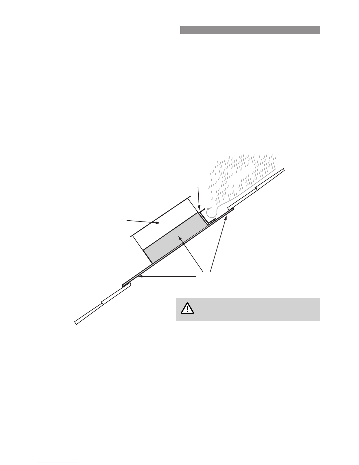
Installations where the Cooler is more than 4m downstream from the roof peak should be tted with an additional
water-diverting channel on the dropper duct high side, that extends beyond the dropper duct sides by at least
50mm (see diagram below).
NOTE
This diagram is for Rinnai C Series Models.
3.4 DROPPER DUCT INSTALLATION GUIDELINES
•
The dropper duct on which the Cooler is mounted MUST BE properly secured to the roof structure or timbers.
•
Ensure the dropper duct does not contact the ceiling joists or other structural members that can transmit
vibration.
•
If possible, the dropper duct should be positioned to the rear or on the service side of the home.
•
It should also be as far down the roof as practicable.
•
Rinnai recommend installing a diffuser or cone in the base of the dropper box. This will assist distributing the
airow evenly into the duct system and can also reduce noise levels.
Flashing
Water diverter channel
Dropper Duct
Rain water
3. COOLER HARDWARE
Page 9

Rinnai 9 Evap AC IM
4.1 DROPPER DUCT INSTALLATION AND FITTING THE COOLER
•
The dropper duct size for all Rinnai C Series models is 550mm X 550mm.
•
Rinnai C Series Coolers MUST use a dropper duct with an out turned ange (15-20mm). This is installed on an
angle through the roof.
•
A spirit level is needed to set the correct
angle to the dropper duct. Rinnai
levelling templates are advisable.
NOTE
The levelling templates DO NOT come as standard, they
MUST BE ordered through the Rinnai Sales Centre.
•
Determine the point of penetration through the roof and prepare the opening according to the type of building
construction and roong material.
•
Frame the roof rafters to the correct width to suit the dropper duct.
•
Position the 2 templates to each side of the dropper duct, under the out turned ange, and with the right angle
bracket hard against the dropper duct corner.
•
The templates provide a 50mm clearance (mid-level) for corrugated iron roofs, and 100mm clearance (top of
template) for tile roofs, to give the correct height through the roof opening.
•
Use the 50mm template position when resting the templates on top of the corrugated iron roof material, whereas
the 100mm template position is used with the templates placed on the roof tile batten.
•
Clamp the templates in position, or use a screw or rivet through the template hole provided to securely hold
them to the dropper duct.
•
Insert the dropper duct between the roof rafters (see diagram).
•
Ensure the template levelling bracket is positioned on the high roof side of the dropper duct.
•
Rest the templates equally on the tile battens or roof timbers, at both sides of the dropper duct.
•
Place a spirit level on the templates levelling bracket, and raise one of the template ends (if necessary) until a
level plane is reached.
•
Depending on the pitch of the roof, either the lower or the higher template end will need raising, to level the
bracket.
•
This procedure will also locate the correct dropper duct height through the roof opening.
•
When the template bracket is level, mark and/or x the dropper duct to the roof frame timbers using bolts or
coach screws.
•
Be sure to use the level on both
template sides to correctly position the
dropper duct.
NOTE
The Cooler outlet has an 8mm clearance from the
dropper duct for the bolt or screw heads.
•
The unit’s power supply and wall control leads are pre-wired to the Cooler control module.
•
These leads feed down from the base inside the dropper duct, and then out into the roof cavity through a 43mm
hole in the dropper duct.
•
This hole MUST BE on the left-hand-side on the low side of the roof. This will accommodate the loom grommet
and allow the wires to be retracted from the dropper duct.
43mmhole on front LHS
Tile batten
Dropper duct
Template hole
Template clamping
Roof rafter
Bubble level on levelling bracket
50mm for corrugated roof
100mm for tiled roof
4. INSTALLATION - C SERIES
Page 10

Rinnai 10 Evap AC IM
4.2 FITTING THE RINNAI C SERIES COOLER
•
The Cooler should now be mounted into position. Insert the Cooler’s air outlet fully into the dropper duct.
•
Ensure the Cooler base sits fully on the dropper box ange and that the base latching brackets (four) retract over
the ange on both sides of the dropper, to lock it onto the dropper duct.
•
Fold the end of all four latching brackets in towards the dropper box. Using the hole at the end of the latching
bracket as a guide, drill a 3mm pilot hole through the dropper box only. DO NOT penetrate the plastic chassis.
Four 8g x 3/8” stainless steel screws should be inserted to secure the four latching brackets to the dropper box.
•
The Cooler’s smallest lter pad and the water supply connection tting MUST BE on the high side of the roof.
•
Ensure the 3 pin power plug and lead, together with the Wall Control connection lead, are also fed to the inside
of the dropper duct before retracting the wires and tting the grommet.
4. COOLER INSTALLATION
Page 11

Rinnai 11 Evap AC IM
5.1 A SERIES DROPPER DUCT SPECIFIC
•
All Rinnai A Series units sit on a 550mm x 550mm dropper box with a 15-20mm out
turned ange.
•
Rinnai A Series units can also be installed on an existing dropper box. Ensure the
dropper box is in a sound condition and the top of the dropper box is level.
•
Rinnai A Series units may also be installed using a dropper box transition piece
(refer to Rinnai Sales Department).
•
The dropper box MUST BE positioned as per the following diagram.
•
Secure the dropper duct vertically, so the Cooler is level when placed on top of it.
•
Ensure the 3 pin power supply plug and lead, the Wall Control Loom connection
lead, and the rubber grommet, are fed to the inside of the dropper duct.
•
Cut a 43mm hole in the dropper duct below the roof line, on the left-hand-side on
the low side of the roof, to accept the wiring grommet. This will allow the 3-pin plug
and lead, and the Wall Control Loom connection lead to be withdrawn from the
dropper into the roof cavity.
5.2 FITTING A SERIES OPTIONAL WINTER-SEAL
•
For detailed instructions please refer to Rinnai A Series Winter-Seal Installation Instructions provided with the
Rinnai A Series Winter-Seal kit.
•
This Procedure MUST BE completed before the Cooler is mounted onto the dropper duct, preferably before the
Cooler is lifted up onto the roof.
•
Gently lift the unit up so that you can see the Cooler’s air outlet.
•
On the Winter-Seal blades is an orange sticker indicating the bottom. This sticker should be facing down when
the cooler is in its nal position.
•
Insert one end of the winter seal blades into the mounting holes provided on the base of the cooler.
•
Lock the other side into place, ensuring that they have been placed in the correct direction and that they are
both free moving.
•
Then proceed with the mounting of the cooler into the dropper duct.
NOTE
The Rinnai A Series accepts the Rinnai A Series Winter-Seal.
5.3 FITTING THE RINNAI A SERIES COOLER
•
The Rinnai A Series Cooler chassis comprises latching brackets to secure the unit to the dropper box. To assist
with connection it is important the dropper box has a 15-20mm outward turned ange.
•
In addition to the latching brackets the unit MUST BE secured to the dropper box and the cooler chassis with
screws, refer below for method:
1. Fold the end of all four latching brackets in towards the dropper box.
2. Using the 5mm hole in the bracket as a guide secure with 8g stainless steel screws.
Cut hole in this position
using 43mm hole saw
below roof line to accept
wiring grommet in this
corner. (Closest to Cooler
Control Box)
High side of roof
5. INSTALLATION - A SERIES
Page 12

Rinnai 12 Evap AC IM
6.1 WIRING CONNECTION RINNAI NETWORKERS
The Rinnai Networker backing plate has 4 terminal points for the connection
of Thermostat wires. When connecting, use the top 2 terminal points marked
TW1 and TW2 or the bottom 2 terminal points also marked TW1 or TW2.
Never use a combination of terminals when connecting to a single appliance.
For example; A Rinnai Networker operating a cooler and a heater would
have the 2 bottom terminals connected to the heater and the 2 top terminals
connected to the cooler.
Run a twin wire cable (i.e. gure 8 cable - 0.75mm2) from the Cooler to the
Rinnai Networker.
•
Remove the backing plate from the Rinnai Networker by unclipping it at the
sides.
•
Draw the wires from the wall cavity and feed them through the opening in
the backing plate, connect the cable to the terminal connections on the
backing plate before mounting it on the wall and re-assembling the Rinnai
Networker.
•
Connect the cable to the Rinnai Networker connection lead terminal block
at the Cooler.
6.2 INSTALLING DUAL RINNAI NETWORKERS
It is possible to have two Rinnai Networkers connected together on a system.
The Rinnai Networkers should be wired in parallel, never in series (see
diagram of typical wiring). The two Rinnai Networkers are identied as either
Master or Slave. All Rinnai Networkers come set as Master by default, and the
slave Rinnai Networker will need to be congured upon installation.
NOTE
Both Rinnai Networkers cannot be set as Master on a system
otherwise it will malfunction. Both Rinnai Networkers cannot
be set as Slave otherwise the system will lock out.
6.3 DUAL RINNAI NETWORKERS
Adjustments to the cooler settings can be made from either Rinnai Networker; but the settings are common to
both Rinnai Networkers. If an adjustment is made on one Rinnai Networker it is immediately reected on the other
Rinnai Networker.
When the cooler is operating in AUTO mode, the Master Rinnai Networker only will be sensing the inside comfort
level, unless the cooler has been designated to the Slave. This means the Master Rinnai Networker should be
located in the most appropriate location to control the inside comfort level.
Once the location for the Master and Slave controllers has been determined, the Rinnai Networker addresses
should be congured. All Rinnai Networkers come set as Master by default, which means only the Slave Rinnai
Networker needs to be congured.
A Master Rinnai Networker can be identied by the word “clock” beside Key 5 (while the Rinnai Networkers are in
the off position). Initially, both Rinnai Networkers upon power up will have the word “clock” beside key 5, because
they are both still Masters at this stage.
6. NETWORK CONNECTION
Page 13

Rinnai 13 Evap AC IM
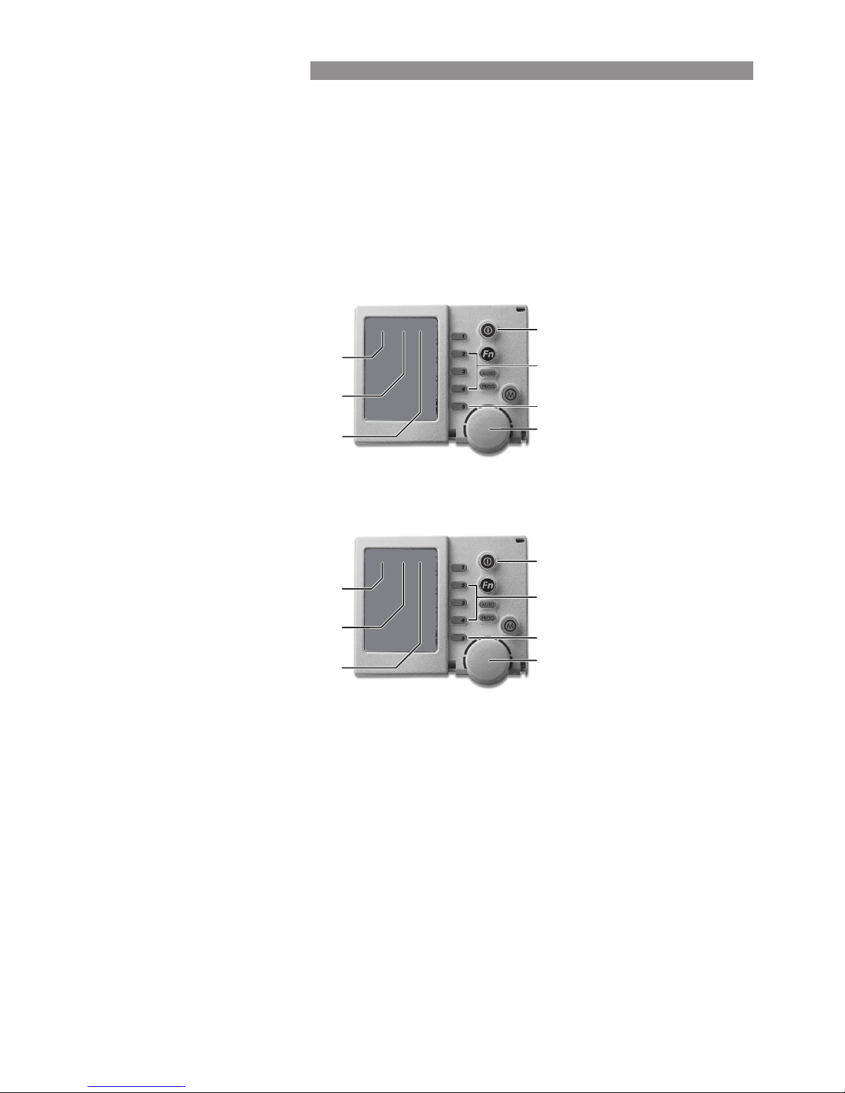
6.4 MASTER AND SLAVE ADDRESSING
•
Press the clock Key 5, and across the top a scrolling message should
say “Clock setting mode”, and after the message has nished the time
will begin ashing.
•
Push and hold Keys 2 & 4, until the screen displays this message “Installer
parameter access”
•
After the message has nished, push the Mode key until the screen
displays - n01 ID00:1 at the top (see diagram).
•
Rotate the circular dial to change the parameter value displayed at the
top right of screen to the number required for the Slave e.g. Slave=2.
•
Once this parameter value has been set, push the ON/OFF button to exit
this Installer set-up program.
Unit
Type
Parameter
Value
Master 1
Slave 2
Networker ID
Parameter Number
Parameter Value
This Rinnai Networker will now become the Slave Rinnai Networker, and the installer parameters can no longer
be accessed from this Rinnai Networker. The Master Rinnai Networker MUST now be used to access the installer
parameters.
6.5 WIRING THE MANUAL WALL CONTROL
After the Cooler’s power supply and pre-wired wall control leads are fed
down from the base into the roof cavity, connect the 20-metre wall control
loom plug to the cooler’s lead plug.
•
Ensure the wall control is positioned so that it is within reach of the cooler
using the 20-metre wire loom assembly supplied.
•
Wall Controls accept the polarised plug connection. The Manual wall
control has a small loom to connect the polarised plug to.
6.6 SETTING UP MULTIPLE COOLERS ON THE NETWORK
To ensure each Cooler is congured correctly to the Rinnai Networker
see the instructions below and refer to the Rinnai Networker Advanced
Programming Manual No. 400 (Available on request from Rinnai Customer
Service).
As the Rinnai Networker is polarity sensitive when more than one Cooler is
installed on a Rinnai Networker all the Coolers should be wired in parallel
(see diagrams above).
To ensure each Cooler is congured correctly to the Rinnai Networker, each
Cooler MUST BE:
•
Given a different specic identication number, starting at No. 1.
•
Designated to a zone (refer to the Rinnai Networker Advanced
Programming Manual No. 404).
Each Cooler comes with the ID number set at number 1. To give it a new
number, rst complete the installation and wiring of all the units, as described
previously and follow the instructions on the next page. (Changing an
Identication Number)
Typical A & C Series Application
20 metre
wall control
loom
6. NETWORK CONNECTION
Page 14
Rinnai 14 Evap AC IM
6.7 CHANGING AN IDENTIFICATION NUMBER
•
To change the ID number a cooler MUST BE powered and congured individually.
•
So, turn OFF the power to all the other coolers and heaters on the Network System.
Use the Installer Set-Up program as follows.
•
Turn the Rinnai Networker OFF.
•
Press (clock) Key 5 and the screen will display the message “Clock setting mode”. After the message has
nished ensure that the time is ashing.
•
Now simultaneously press and hold the 2nd & 4th keys for 3-5 seconds until the message displays “Installer
parameter access”. After the message has nished the display will appear like this. If a Heater is also on the
system you will need to press the Mode button.
•
Rotate the rotary dial to change the parameter value displayed at the top right of screen to the unit number
required for this Cooler (as shown below by unit number “ 2”).
•
Wait one minute before proceeding to allow for the programming change.
•
Press the Rinnai Networker ON/OFF button to exit the program.
•
Turn the power supply at the Cooler OFF to save the new ID number.
•
Repeat the sequence for each Cooler.
•
Then follow the Rinnai Networker Advanced Programming Instructions to allocate the Coolers to their respective
zones.
On/Off Button
Keys 2 and 4
Rotary Dial
Key 5 (Clock)
Parameter Value
Parameter Number
Cooler Number
E0 1 ID07: 1
On/Off Button
Keys 2 and 4
Rotary Dial
Key 5 (Clock)
Parameter Value
Parameter Number
Cooler Number
E0 1 ID07: 2
6. NETWORK CONNECTION
Page 15

Rinnai 15 Evap AC IM
7.1 INLET CONNECTION
The water inlet connection point is under the cooler base on the left hand side, at the high side of the roof. The
connection is via a 1/2” BSP female tting supplied on a exible hose.
7.2 TANK WATER QUALITY MANAGEMENT.
The Rinnai A Series and Rinnai C Series electronic water level sensor automatically maintains the correct water
level within the tank. The Rinnai A Series model is programmed to periodically ush the tank and rell it with clean
water, depending on the operating conditions, and automatically maintain the water quality within the tank. The
Rinnai C Series is tted with an AquaSave module that maintains water purity during the cooler’s operation and
therefore does not ush as often.
7.3 WATER DRAIN CONNECTION
Rinnai A Series and Rinnai C Series models have a drainage connection point at the underside of the base, on the
low side of the roof.
When the cooler’s discharge is likely to fall on a roof or catchment area for potable water, or water reuse, then a
drain MUST BE tted. In some municipalities it is mandatory to t a drain to the cooler. Check with the local authority
regarding the regulations.
Where required Rinnai recommend the drain outlet be plumbed to a suitable point in order to disperse the waste
water away adequately without causing damage or nuisance i.e. overowing roof guttering, accelerated corrosion.
There are two recommended options when connecting drainage to the unit:
•
Option one is for a small diameter pipe which MUST BE secured with PVC cement, not a screw. This slides over
the Ø19.8mm tting detailed in Figure 1.
•
Option two is for a larger diameter pipe and prior to connection, the snorkel outlet MUST BE modied by cutting
and de-burring at the “CUT LINE” shown in Figure 1. Once complete, slide on the large diameter pipe, drill a
pilot hole Ø3mm and secure with a 8gx3/8 stainless steel screw as shown in Figure 2.
Ensure that all eld supplied drainage pipe is rigid (not exible) and UV stabilised.
Ensure any drain has a continuous fall, the joints and ttings are adequately sealed, and that all penetrations in
and out of the roof cavity are sealed against water entry into the building.
The drain pipe MUST also be properly supported along its entire run, and MUST NOT place strain on the Cooler’s
outlet tting or base.
For installations on tiled roofs where a drain may not be required, Rinnai recommend tting a water distribution
spreader to the Cooler’s drain outlet.
7. WATER CONNECTION
Page 16

Rinnai 16 Evap AC IM
8.1 START UP
Rinnai Cooler with Dump Valve tted will have a 15 second delay on start up.
On start up, the Rinnai C Series ServoSeal damper will also open before any other function.
If the Cooler has been OFF for longer than 60 minutes the tank will require relling. Allow approximately 3-5
minutes depending on the water pressure.
8.2 PRE-WET
The Cooler has been pre-programmed to automatically saturate the lter pads when the pump is turned ON.
Pre-wet is the process of running the pump and wetting the pads without the fan operating ensuring full pad
saturation and optimum cooling potential when the fan starts.
Pump Off Time Pre-wet Time
Less Than 2 minutes No Pre-wet
Between 2 and 10 minutes Pre-wet 1 minute
Longer than 10 minutes Pre-wet 4 minutes
Longer than 60 minutes
Tank has to be lled, therefore total time
including Pre-wet is 5 to 7 minutes
8.3 TANK WATER QUALITY AND REPLENISHMENT DURING OPERATION
During the Cooler’s operation with the pump operating, the Cooler will be evaporating water from the tank and
automatically relling itself.
Rinnai A Series models will periodically, after a specied number of tank rells, ush out the tank (discharging
water from the drain outlet for approximately 1 minute) without stopping the Cooler.
How frequently this ush occurs will vary according to local water conditions and the rate of evaporation.
NOTE
Rinnai C Series will not ush as often, as they are tted with an AquaSave.
8.4 SHUT-DOWN TIMES
When the Cooler is turned OFF at the end of use, the controls are programmed to wait 60 minutes before
commencing Shut-down.
This Shut-down procedure starts with draining the tank (approximately 60 seconds). Rinnai C Series models will
also close the ServoSeal damper at the start of the Shut-down procedure. Then a wash cycle is performed to clean
the tank for approximately 30 seconds.
8. TIMING & COOLER FUNCTIONS
Page 17

Rinnai 17 Evap AC IM
9.1 REMOVING THE FRONT AND REAR PADS
For general servicing, remove the front and back pads to access all components.
•
Loosen the 4 plastic thumbscrew knobs on the c ooler’s roof until the large front pad can be lifted up enough to
clear the bottom edge.
•
Swing the large front pad out at the top edge.
•
Remove the 2 thumbscrews above the small back pad completely.
•
Raise the roof until the small back pad has enough clearance at the top to be removed.
•
With the front and rear pad frames removed, the lter pads simply slide up and out of their frames.
9.2 REMOVING THE SIDE PADS
Remove the front and back pads as above, then:
•
Disconnect the 19mm clear hose supplying water to the roof distribution spreader at the tting in the cooler’s
base (squeeze clip then pull to release).
•
Ensure that all thumb screws have been removed.
•
Remove the roof assembly.
•
Slide the lter pads up and out of their frames.
9.3 DISMANTLING THE FRAMEWORK
Complete all the steps above then:
•
From the front of the unit remove all four 10g screws securing the posts to the base caps. Note that the top
brackets are glued to the posts, and cannot be separated.
•
Lift up and remove the 4 PVC support posts, disengaging the pad’s restraining angle brackets.
•
Slide the side pad frames out from the formed brackets at the base of the frames.
•
Remove the side pad frames and external panel assemblies.
9. DISMANTLING
Page 18

Rinnai 18 Evap AC IM
IMPORTANT
Switch OFF the power and unplug the Cooler before touching any wiring. Care MUST BE taken
to ensure electrical components have been isolated before performing any service work, i.e.
water inlet valve, Servo Seal motor. Only an electrically qualied technician should carry out any
service to electrical wiring.
10.1 ISOLATING SWITCH
The Rinnai A Series and Rinnai C Series both have an external power-isolating switch to facilitate servicing.
The switch is located under the front left hand side of the cooler. To access the switch, reach under the front of the
Cooler’s trough and locate the switch. By observing the LED light on the control box you can ascertain whether the
power is on or off. Always test for electrical voltage before commencing any work on the cooler.
10.2 CHECKLIST
•
The ServoSeal damper is not catching and opens fully (Rinnai C Series Models only).
•
The isolating valve on the water supply is turned ON.
•
The water tank lls with water and the water inlet valve closes when the tank is full.
•
There is no foreign matter in the water tank or fan housing.
•
The pads are correctly located.
•
The pump operates when turned ON at the Wall Control.
•
The fan operates through the entire speed range.
•
For even water distribution with the pads in position and the Cooler in operation.
•
The water drains completely from the tank and that any external drain piping is not blocked or restricted.
•
That the optional dump valve functions correctly by isolating the power to the unit and ensuring that the tank
drains completely.
NOTE
New cooling pads should be thoroughly ushed before use so, following commissioning, run
the pump for 30 minutes without the fan, and then drain the tank fully. This will prime the pads,
ush out some of the new pad odour, and remove any foreign matter that may have settled in the
system during transport.
10.3 WHAT IF THE FAN MOTOR WILL NOT START?
Check:
•
The 10 Amp fuse in the meter box has not blown.
•
The Cooler’s 3-pin supply plug is correctly located in the power socket.
•
For power at the power socket (plug in another appliance and test).
•
The isolating switches at the unit and the supply power socket are turned ON.
•
The unit is turned ON at the Rinnai Networker Wall Control.
•
The fan is not in a delay due to ServoSeal damper, tank lling, or pad Pre-Wet operation.
•
The motor will spin freely with adequate tip clearance (approximately 2mm).
•
The motor is not hot, causing the auto-reset thermal overload switch in the fan motor to open circuit.
•
The motor speed sensor has not been damaged or displaced (where tted).
•
That all electrical connections are secure, and if the motor will not start, call Rinnai for service.
10.4 WHAT IF THE PUMP WILL NOT START?
Check:
•
The 10 Amp fuse in the meter box has not blown.
•
The Cooler’s 3-pin supply plug is correctly located in the power socket.
•
For power at the power socket (plug in another appliance and test).
10. COMMISSIONING CHECKLIST
Page 19

Rinnai 19 Evap AC IM
•
The isolating switches at the unit and the supply power socket are turned ON.
•
The unit is turned ON at the Rinnai Networker / Manual Wall Control.
•
The pump is not in a delay due to ServoSeal damper, or tank lling operation.
•
The pump impeller is not blocked or obstructed.
•
All electrical connections are secure, and if the pump will not start, call Rinnai for service.
10. COMMISSIONING CHECKLIST
Page 20

Rinnai 20 Evap AC IM
IMPORTANT
Exhaust fans may be required if insufcient free exhaust area exists. If the exhaust fan is the only
exhaust or ventilation outlet, then its capacity should be at least equal to the Cooler’s air output.
Door = 1.6m² Hinged Window = 0.3m² Sliding Window = 0.7m²
Average ventilation area provided by various openings when fully opened.
Model
Number of average size windows & doors
(suggestive only)
Highest
Fan
Setting
Lowest
Fan
Setting
C Series
A Series
C20 A20 Two sliding windows or Five hinged windows 1.5 m
2
0.9 m
2
C30 A30 One door and a hinged window
1.9 m
2
1.1 m
2
C40 A40 / A50 Three sliding windows or one door & two hinged windows 2.3 m
2
1.4 m
2
C50 A60 Four sliding windows or one door and four hinged windows 2.8 m
2
1.7 m
2
C60 A70 Five sliding windows or one door and ve hinged windows 3.1 m
2
1.9 m
2
C70 A80 Six sliding windows or one door and six hinged windows 3.4 m
2
2.1 m
2
11. EXHAUST AND VENTILATION
Page 21

Rinnai 21 Evap AC IM
A80
60.0
81.0
15
1000
7.3
11
1200
90°
20 or 40
Flexible hose connection with 1/2” BSP thread
Networker - twin wire cable (gure 8 cable). Manual - 20 metre wiring loom
550 x 550 with 15-20 mm Flange out
Both C Series & A Series models can have either the Networker wall control or the Manual wall control
A70
60.0
81.0
15
1000
7.3
11
A60
53.0
71.5
15
1000
7.3
11
A50
51.0
69.5
15
750
4.9
11
A40
50.5
69.0
15
750
4.9
11
A30
49.0
67.0
15
750
4.9
11
A20
47.5
65.5
15
315
2.4
6
C70
57.6
79.8
12
1000
7.3
11
900
21°
C60
55.6
77.8
12
750
4.9
11
C50
56.6
80.3
12
750
4.9
11
C40
55.6
77.8
12
750
4.9
11
C30
51.5
70.4
12
750
4.9
11
C20
49.5
67.3
12
315
2.4
6
Model
Dry
Wet
Tank Capacity (litres)
Watts
Amps
Fan Impeller Blades
Minimum Dropper Box Length (mm)
Angle of Dropper Box (degrees)
Dump Drain Connection (mm)
Water Connection
The type of loom
depends on the wall
control used.
Dropper Box Size (mm)
Wall Controller
Weight (kg)
Motor
NOTE
Loom
12. TECHNICAL SPECIFICATIONS
Page 22

Rinnai 22 Evap AC IM
NOTES
Page 23

Rinnai 23 Evap AC IM
NOTES
Page 24

B063093 24 Evap AC IM Issue 1 - 27/10/15
CONTACTS
Australia Pty. Ltd.
ABN 74 005 138 769
Rinnai has a Service and Spare Parts network with personnel who are fully trained
and equipped to give the best service on your Rinnai appliance. If your appliance
requires service, please call our National Help Line. Rinnai recommends that this
appliance be serviced every 2 years.
Head Office
100 Atlantic Drive,
Keysborough VIC 3173
P.O. Box 460
Braeside, Victoria 3195
Product Sales and Service - National
Phone: 1300 555 545* Fax: 1300 555 655*
Technical Helpline and Spare Parts
National (Mon-Fri 8am - 5.30pm EST)
Phone: 1300 555 545* Fax: 1300 300 141*
*Cost of a local call higher from mobile or public phones.
E-mail: enquiry@rinnai.com.au
For further information visit: www.rinnai.com.au
 Loading...