


User’s Guide |
RIGOL |
Publication number DS1000CA-080512
April 2008
DS1000CA Series Digital Oscilloscopes
DS1302CA, DS1202CA, DS1102CA, DS1062CA
Copyright © 1998-2008 RIGOL Technologies, Inc.
All Rights Reserved

RIGOL
zCopyright ©1998-2008 RIGOL Technologies, Inc. All Rights Reserved.
zRIGOL products are protected by patent law in and outside of P.R. China.
zInformation in this publication replaces all previously corresponding material.
zRIGOL Technologies, Inc. reserves the right to modify or change part of or all the specifications and pricing policies at company’s sole decision.
NOTE: RIGOL is registered trademark of RIGOL Technologies, Inc.
Copyright ©1998-2008 RIGOL Technologies, Inc. |
I |
User’s Guide for DS1000CA Series |
|

RIGOL
Safety Notices
Review the following safety precautions carefully before operating the instrument to avoid any personal injuries or damages to the instrument and any products connected to it.
To avoid potential hazards use the instrument as specified by this user’s guide only.
The instrument should be serviced by qualified personnel only.
To Avoid Fire or Personal Injury.
Use Proper Power Cord. Use the power cord designed for the instrument and authorized in your country only.
Connect and Disconnect Accessories. Do not connect or disconnect probes or test leads while they are connected to a voltage source
Ground The Instrument. The oscilloscope is grounded through the grounding conductor of the power cord. To avoid electric shock the instrument grounding conductor(s) must be grounded properly, before making connections to the input or output terminals of the instrument.
Connect The Probe. The probes’ ground terminals are at the same voltage level of the instrument ground. Do not connect the ground terminals to a high voltage.
Observe All Terminal Ratings. To avoid fire or shock hazard, observe all ratings and marks on the instrument. Follow the user’s guide for further ratings information before making connections to the instrument.
Do Not Operate Without Covers. Do not operate the instrument with covers or panels removed.
II |
Copyright ©1998-2008 RIGOL Technologies, Inc. |
|
User’s Guide for DS1000CA Series |

RIGOL
Use Proper Fuse. Use the fuse of the type, voltage and current ratings as specified for the instrument.
Avoid Circuit or Wire Exposure. Do not touch exposed connections and components when power is on.
Do Not Operate With Suspected Failures. If suspected damage occurs with the instrument, have it inspected by qualified service personnel before further operations.
Provide Proper Ventilation. Refer to the installation instructions for proper ventilation of the instrument.
Do not Operate in Wet/Damp Conditions.
Do not Operate in an Explosive Atmosphere.
Keep Product Surfaces Clean and Dry.
The disturbance test of all the models meet the limit values of A in the standard of EN 61326: 1997+A1+A2+A3, but can’t meet the limit values of B.
Measurement Category
The DS1000CA series Digital Oscilloscope is intended to be used for measurements in Measurement Category I.
Measurement Category Definitions
Measurement Category I is for measurements performed on circuits not directly connected to MAINS. Examples are measurements on circuits not derived from MAINS, and specially protected (internal) MAINS derived circuits. In the latter case, transient stresses are variable; for that reason, the transient withstand capability of the equipment is made known to the user.
Copyright ©1998-2008 RIGOL Technologies, Inc. |
III |
User’s Guide for DS1000CA Series |
|
RIGOL
WARNING
IEC Measurement Category I. The input terminals may be connected to circuit terminal in IEC Category I installations for voltages up to 300 VAC. To avoid the danger of electric shock, do not connect the inputs to circuit’s voltages above 300 VAC.
Transient overvoltage is also present on circuits that are isolated from mains. The DS1000CA series Digital Oscilloscopes is designed to safely withstand occasional transient overvoltage up to 500 Vpk. Do not use this equipment to measure circuits where transient overvoltage could exceed this level.
Safety Terms and Symbols
Terms in This Guide. These terms may appear in this guide:
WARNING: Warning statements identify conditions or practices that could
!result in injury or loss of life.
CAUTION: Caution statements identify conditions or practices that could
!result in damage to this product or other property.
Terms on the Product: These terms may appear on the product.
DANGER indicates an injury hazard may be immediately accessible.
WARNING indicates an injury hazard may be not immediately accessible.
CAUTION indicates that a potential damage to the instrument or other property might occur.
Symbols on the Product: These symbols may appear on the Instrument:
!
Hazardous |
Refer to |
Protective |
Grounding |
Test |
Voltage |
Instructions |
Earth Terminal |
Terminal |
Grounding |
|
|
|
of Chassis |
Terminal |
IV |
Copyright ©1998-2008 RIGOL Technologies, Inc. |
|
User’s Guide for DS1000CA Series |

RIGOL
General-Purpose Oscilloscopes
RIGOL DS1000CA-Series digital oscilloscopes offer exceptional waveform viewing and measurements in a compact, lightweight package. The DS1000CA series is ideal for production test, field service, research, design, education and training involving applications of analog circuit tests and troubleshooting.
Product features:
zDual Channel, Bandwidth: 300MHz (DS1302CA) 200MHz (DS1202CA) 100MHz (DS1102CA 60MHz (DS1062CA)
zColor TFT LCD, 320×234 pixels resolution.
zUSB storage and printing supports, firmware upgrade via USB interface.
zAdjustable waveform intensity, more effective waveform viewing.
zOne-touch automatic setup, ease of use (AUTO).
z10 Waveforms, 10 setups, supports CSV and bitmap format.
zDelayed Scan Function, easy to give attention to both details and overview of a waveform.
z20 Automatic measurements.
zAutomatic cursor tracking measurements.
zWaveform recorder, record and replay dynamic waveforms.
zUser selectable fast offset calibration.
zBuilt-in FFT function, Frequency Counter.
zDigital filters, includes LPF, HPF, BPF, BRF.
zPass/Fail Function, optically isolated Pass/Fail output.
zAdd, Subtract and Multiply Mathematic Functions.
zAdvanced trigger types include: Edge, Video, Pulse width, Slope, Alternative.
zAdjustable trigger sensitivity.
zMultiple Language User Interface.
zPop-up menu makes it easy to read and easy to use.
zBuilt-in Chinese and English help system.
zEasy-to-use file system supports Chinese & English characters file name input.
Copyright ©1998-2008 RIGOL Technologies, Inc. |
V |
User’s Guide for DS1000CA Series |
|

RIGOL
Content
Safety Notices .............................................................................................. |
II |
General-Purpose Oscilloscopes........................................................................ |
V |
CHAPTER 1: GETTING STARTED ..................................................................... |
1-1 |
The Front Panel and the User Interface........................................................ |
1-2 |
To Inspect the Instrument .......................................................................... |
1-6 |
To Perform a Functional Check .................................................................... |
1-7 |
To Compensate Probes ............................................................................... |
1-9 |
To Display a Signal Automatically............................................................... |
1-10 |
To Set Up the Vertical Window .................................................................. |
1-11 |
To Set Up the Horizontal System ............................................................... |
1-13 |
To Trigger the Oscilloscope ....................................................................... |
1-15 |
CHAPTER 2: OPERATING YOUR OSCILLOSCOPE............................................... |
2-1 |
Understand the Vertical System ................................................................... |
2-2 |
Understand the Horizontal System ............................................................. |
2-25 |
Understand the Trigger System ................................................................. |
2-31 |
To Set Up the Sampling System................................................................. |
2-49 |
To Set Up the Display System.................................................................... |
2-53 |
To Store and Recall Waveforms or Setups .................................................. |
2-56 |
To Set Up the Utility ................................................................................. |
2-64 |
To Measure Automatically ......................................................................... |
2-83 |
To Measure with Cursors........................................................................... |
2-90 |
To Use Run Control Buttons ...................................................................... |
2-96 |
CHAPTER 3: APPLICATION & EXAMPLES.......................................................... |
3-1 |
Example 1: Taking Simple Measurements ..................................................... |
3-1 |
Example 2: View a Signal Delay Caused by a Circuit...................................... |
3-2 |
Example 3: Capture a Single-Shot Signal ...................................................... |
3-3 |
Example 4: To Reduce the Random Noise on a Signal ................................... |
3-4 |
Example 5: Making Cursor Measurements .................................................... |
3-6 |
Example 6: The application of the X-Y operation ........................................... |
3-8 |
Example 7: Triggering on a Video Signal..................................................... |
3-10 |
Example 8: FFT Cursor measurement......................................................... |
3-12 |
Example 9: Pass/Fail Test .......................................................................... |
3-13 |
VI |
Copyright ©1998-2008 RIGOL Technologies, Inc. |
|
User’s Guide for DS1000CA Series |
|
RIGOL |
CHAPTER 4: PROMPT MESSAGES & TROUBLESHOOTING |
................................. 4-1 |
Prompted Messages ................................................................................... |
4-1 |
Troubleshooting ......................................................................................... |
4-3 |
CHAPTER 5: SPECIFICATIONS........................................................................ |
5-1 |
CHAPTER 6: APPENDIX.................................................................................. |
6-1 |
Appendix A: Accessories ............................................................................. |
6-1 |
Appendix B: Warranty................................................................................. |
6-2 |
Appendix C: Maintenance ........................................................................... |
6-3 |
Appendix D: Contact RIGOL ........................................................................ |
6-4 |
Index.............................................................................................................. |
i |
Copyright ©1998-2008 RIGOL Technologies, Inc. |
VII |
User’s Guide for DS1000CA Series |
|
RIGOL
Chapter 1 : Getting Started
This chapter covers the following topics:
The front panel and user interface
To inspect the instrument
To perform a functional check
To compensate probes
To display a signal automatically
To set up the vertical system
To set up the horizontal system
To trigger the oscilloscope
Copyright ©1998-2008 RIGOL Technologies, Inc. |
1-1 |
|
User’s Guide for DS1000CA Series |
|
|

RIGOL
The Front Panel and the User Interface
The first thing to do with a new oscilloscope is to know its front panel. This chapter helps to be familiar with the layout of the knobs and keys and how to use them. Read the chapter carefully before further operations.
Figure 1-1, Front Panel; the knobs are used most often and are similar to the knobs on other oscilloscopes. The buttons allow you to use some of the functions directly but also bring up soft button menus on the screen, which enable the access to many measurement features associated with advanced functions, mathematics, and reference or to run control features.
Figure 1-1
DS1000CA-Series Oscilloscope’s Front Panel
DS1000CA series oscilloscopes provide an easy-to-use user interface, the definitions of the buttons and the knobs are as follows:
Menu buttons: Associated with Measure, Cursor, Acquire, Display, Storage, and Utility menus.
1-2 |
Copyright ©1998-2008 RIGOL Technologies, Inc. |
|
|
User’s Guide for DS1000CA Series |
|
RIGOL
Vertical buttons: |
Associated with CH1, CH2, MATH and REF menus, the OFF |
|
button can set waveform or menu which currently active off. |
Horizontal buttons: Associated with horizontal MENU.
Trigger buttons: Associated with trigger MENU, instant action to set 50% trigger level and FORCE trigger.
Action buttons: |
Include run control buttons for AUTO and RUN/STOP. |
Function buttons: Five blue buttons from top to bottom on the right of the LCD screen, which set choice of operations in the currently active menu.
Knobs: |
For the adjustment of vertical or horizontal |
, |
|
|
and trigger |
. |
|
Copyright ©1998-2008 RIGOL Technologies, Inc. |
1-3 |
|
User’s Guide for DS1000CA Series |
|
|

RIGOL
Figure 1-2
Front Panel Controls
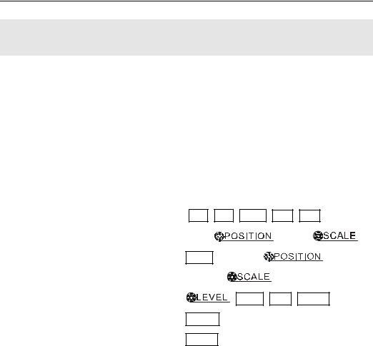
Notation definitions in this User’s Guide:
Throughout this manual, notation symbols of buttons and knobs are the same of those on front-panel.
zA box around the name of the key denotes MENU function buttons on front-panel, such as Measure.
z( ) denotes the multi-function knob
  .
.
z


 denotes the two POSITION knobs.
z


 denotes the two SCALE knobs.
z


 denotes the LEVEL knob.
zThe name with a drop shadow denotes the menu operating key, such as WAVEFORM soft key in STORAGE menu.
1-4 |
Copyright ©1998-2008 RIGOL Technologies, Inc. |
|
|
User’s Guide for DS1000CA Series |
|

RIGOL
Location of |
Trigger point in |
Trigger point in |
waveform window |
||
Running status in memory |
memory |
waveform window |
Channel 1
Channel 2 |
|
|
|
|
|
Menu |
|
|
|
|
|
||
|
|
|
|
|
Waveform |
|
|
|
|
|
|||
|
|
|
|
|
|
display window |
Figure 1-3
Display screen
Copyright ©1998-2008 RIGOL Technologies, Inc. |
1-5 |
|
User’s Guide for DS1000CA Series |
|
|

RIGOL
To Inspect the Instrument
After receiving a new DS1000CA series oscilloscope, please inspect the instrument as follows:
1.Inspect the shipping container for damage.
Keep the damaged shipping container or cushioning material until the contents of the shipment have been checked for completeness and the instrument has been checked mechanically and electrically.
2.Check the accessories.
Accessories supplied with the instrument are listed in "Accessories" in this guide. If the contents are incomplete or damaged notify the RIGOL Sales Representative.
3.Inspect the instrument.
In case there is any mechanical damage or defect, or the instrument does not operate properly or fails performance tests, notify the RIGOL Sales Representative.
If the shipping container is damaged, or the cushioning materials show signs of stress, notify the carrier as well as the RIGOL sales office. Keep the shipping materials for the carrier’s inspection.
RIGOL offices will arrange for repair or replacement at RIGOL’s option without waiting for claim settlement.
1-6 |
Copyright ©1998-2008 RIGOL Technologies, Inc. |
|
|
User’s Guide for DS1000CA Series |
|
RIGOL
To Perform a Functional Check
Perform this quick functional check to verify that the instrument is operating correctly.
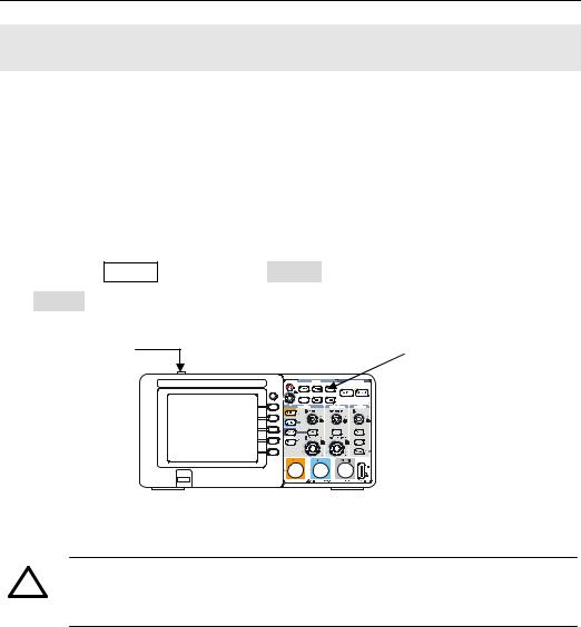
1. Turn on the instrument.
¾Use the power cord designed for the oscilloscope only.
¾Use a power source that delivers 100 to 240 VACRMS, 45Hz to 440Hz.
¾Turn on the instruments, and wait until the display shows the waveform window.
¾Push the Storage button, select Storage in the top menu box and push the Factory menu box.
Power button |
Storage button |
|
Figure 1-4
Turn on the instrument
!WARNNING:
To avoid electric shock, be sure the oscilloscope is properly grounded.
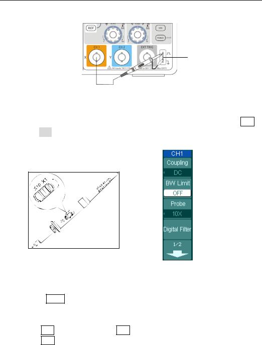
2 Input a signal to a channel of the oscilloscope
Set the attenuation switch on the probe to 10X and connect the probe to Channel 1 on the oscilloscope.
To do this:
¾Align the slot in the probe connector with the key on the CH 1 BNC connector.
¾Push to connect, and twist to the right to lock the probe in place.
¾Attach the probe tip and ground lead to the PROBE COMP connector.
Copyright ©1998-2008 RIGOL Technologies, Inc. |
1-7 |
|
User’s Guide for DS1000CA Series |
|
|
RIGOL
Probe compensator
Figure 1-5
Attach the probe
Set the probe attenuation of the oscilloscope to 10X. To do this, push CH1→
Probe→10X.
 Probe scale
Figure 1-6 |
Figure 1-7 |
Set the probe |
The CH1 menu |
Push the AUTO button. Within a few seconds, a square wave will display (approximately 1 kHz 3 V peakto- peak).
Push the OFF button or push the CH1 button again to turn off Channel 1. Push the CH2 button to turn on channel 2, repeat steps 2 and 3.
1-8 |
Copyright ©1998-2008 RIGOL Technologies, Inc. |
|
|
User’s Guide for DS1000CA Series |
|
RIGOL
To Compensate Probes
Perform this adjustment to match the characteristics of the probe and the channel input. This should be performed whenever attaching a probe to any input channel the first time.
1.From CH1 menu, set the Probe attenuation to 10X (press CH1→Probe→10X). Set the switch to 10X on the probe and connect it to CH1 of the oscilloscope. When using the probe hook-tip, inserting the tip onto the probe firmly to ensure a proper connection.
Attach the probe tip to the Probe compensator connector and the reference lead to the ground pin, Select CH1, and then press AUTO.
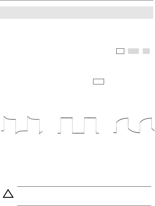
2.Check the shape of the displayed waveform.
Over compensated |
Correctly Compensated |
Under Compensated |
Figure 1-8
Check the shape
3.If necessary, use a non-metallic tool to adjust the trimmer capacitor of the probe for the flattest square wave being displayed on the oscilloscope.
4.Repeat if necessary.
!WARNNING: To avoid electric shock while using the probe, be sure the perfection of the insulated cable, and do not touch the metallic portions of the probe head while it is connected with a voltage source.
Copyright ©1998-2008 RIGOL Technologies, Inc. |
1-9 |
|
User’s Guide for DS1000CA Series |
|
|
RIGOL
To Display a Signal Automatically
The oscilloscope has an automated feature to display the input signal best-fit. The input signal should be 50Hz or higher and a duty cycle is greater than 1%.
Press the AUTO button, the oscilloscope automatically sets up VERTICAL, HORIZONTAL and TRIGGER controls to display the input signal. Adjust the controls manually to get the best results if necessary.
Connect a signal to the Channel 1 (CH1).
1.Connect a signal to the oscilloscope as described above.
2.Press AUTO.
The oscilloscope may change the current settings to display the signal; adjusts the vertical and horizontal scaling, the trigger coupling, type, position, slope, level, and mode.
1-10 |
Copyright ©1998-2008 RIGOL Technologies, Inc. |
|
|
User’s Guide for DS1000CA Series |
|
RIGOL
To Set Up the Vertical Window
Figure 1-9 shows the VERTICAL controls, CH1, CH2, MATH, REF, and OFF buttons and vertical 


 ,
, 


 knobs. Following the exercises in the buttons, knobs, and the status bar to be familiar with the vertical parameters settings.
Figure 1-9
The vertical window
1. Center the signal on the display with the 


 knob.
knob.
The 


 knob moves the signal vertically, and it is calibrated. Note that turning the


 knob, a voltage value is displayed for a short time indicating its value with respect to the ground reference located at the center of the screen. Also notice that the ground symbol on the left side of the display moves in conjunction with the


 knob.
knob.
Measurement hints
If the channel is DC coupled, measuring the DC component of the signal by simply noting its distance from the ground symbol.
If the channel is AC coupled, the DC component of the signal is blocked, allow you to use greater sensitivity to display the AC component of the signal.
Copyright ©1998-2008 RIGOL Technologies, Inc. |
1-11 |
|
User’s Guide for DS1000CA Series |
|
|
RIGOL
Vertical offset back to 0 shortcut key
Turn the 


 knob to change the vertical display position of channel and press the


 knob to set the vertical display position back to 0 as a shortcut key, this is especially helpful when the trace position is far out of the screen and want it to get back to the screen center immediately.
2. Change the vertical setup and notice that each change affects the status bar differently.
zChange the vertical sensitivity with the 


 knob and notice the change in the status bar.
zPress CH1 to turn on Channel 1.
zA soft button menu appears on the display (or remains on if it was already turned on).
zToggle the soft buttons and notice the changes in the status bar. Channel 1 and 2 have a vernier soft button that allows the 


 knob to change the vertical step size in smaller increments. To press Volts/Div soft button to change the step size into Fine or Coarse status.
zPress OFF button to turn off the channel.
Coarse/Fine Shortcut key
The Coarse/Fine vertical control can be set by simply pressing the vertical  knob.
knob.
1-12 |
Copyright ©1998-2008 RIGOL Technologies, Inc. |
|
|
User’s Guide for DS1000CA Series |
|
RIGOL
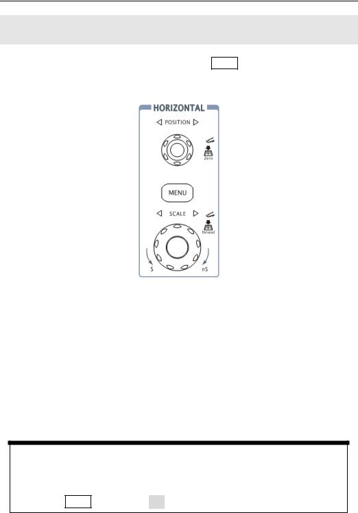
To Set Up the Horizontal System
Figure 1-10 shows the HORIZONTAL controls: MENU button, 


 and
and


 knobs of horizontal system. Following the exercise to familiarize with the buttons, knobs, and status bar.
Figure 1-10
The horizontal system
1. Turn the 


 knob and notice the change in the status bar.
The horizontal 


 knob changes the sweep speed in a 1-2-5 step sequence, and displays the value in the status bar. The time base ranges of the DS1000CA series is from 5ns/div* to 50s/div.
* NOTE: The speed of horizontal scan varies by different models.
Delayed Scan Shortcut key
To press the 


 knob in the horizontal control area on the front-panel is another way to enter or exit Delayed Scan mode and it is equal to the menu operations, MENU→Delayed→ON.
Copyright ©1998-2008 RIGOL Technologies, Inc. |
1-13 |
|
User’s Guide for DS1000CA Series |
|
|

RIGOL
2. The horizontal 


 knob moves displayed signal horizontally on waveform window.
Horizontal offset back to 0 shortcut key
Press the 


 knob to set the horizontal offset to 0 as a shortcut key, this is especially helpful when the trigger point is far out of the screen and want it to get back to the screen center immediately.
3.Press the MENU key to display the TIME menu.
To enter or exit the Delayed Scan mode, set the display to Y-T, X-Y or ROLL mode, and turn the horizontal 


 knob to adjust trigger offset.
Horizontal position control
Trig-Offset: In this setting, the trigger position will be changed horizontally when you turning the 


 knob.
knob.
1-14 |
Copyright ©1998-2008 RIGOL Technologies, Inc. |
|
|
User’s Guide for DS1000CA Series |
|

RIGOL
To Trigger the Oscilloscope
Figure 1-11 shows the trigger control: MENU, 50%, FORCE and a 


 trigger level knob. Following the exercises to familiarize with the buttons, trigger level knob and status bar.
Figure 1-11
The trigger control window
1. Turn the trigger Level knob and notice the changes on the display.
On the DS1000CA series oscilloscopes, as you turn the 


 knob or pressing the 50% button, two things will happen on the display for a short time.
¾First, the trigger level value is displayed at the bottom-left of the screen. If the trigger is DC coupled, it is displayed as a voltage value. If the trigger is AC coupled or LF reject, it is displayed as a percentage of the trigger range.
¾Second, a line is displayed showing the location of the trigger level (as long as AC coupling or low frequency reject are not selected).
Trigger Level to 0 Shortcut key
Turn the 


 knob to change the trigger level value and press the
  knob to set trigger level back to 0 as a shortcut key.
Copyright ©1998-2008 RIGOL Technologies, Inc. |
1-15 |
|
User’s Guide for DS1000CA Series |
|
|

RIGOL
2. Change the trigger setup and notice these changes in the status bar.
Press MENU button in the Trigger control.
A soft button menu appears on the display showing the trigger setting choices as shown in Figure 1-12.
·Press the trigger Mode button and choose Edge.
·Press the trigger Source button to select CH1.
·Press the trigger Slope button to choose  .
.
·Press the trigger Sweep button to select Auto.
·Press the trigger Set Up button to enter secondary menu.
Figure 1-12
NOTE: The trigger mode, slope and source change in conjunction with the status bar on the top-right of the screen.
3. Press 50%
The 50% button sets the trigger level to the center of the signal.
4. Press FORCE
Starts an acquisition regardless of an adequate trigger signal, usually used in “Normal” or “Single” trigger mode. This button has no effect if the acquisition is already stopped.
Key point:
Holdoff: A time interval before the oscilloscope response to next trigger signal. During this Holdoff period, the trigger system becomes “blind” to trigger signals. This function helps to view complex signals such as an AM waveform. Press Holdoff button to activate ( ) knob, then turn it to adjust Holdoff time.
1-16 |
Copyright ©1998-2008 RIGOL Technologies, Inc. |
|
|
User’s Guide for DS1000CA Series |
|
RIGOL
Chapter 2 : Operating Your Oscilloscope
By now, a user should understand the VERTICAL, HORIZONTAL and TRIGGER control systems and knows how to determine the system setup from the status bar of a DS1000CA-series digital oscilloscope.
This chapter will go through all groups of front-panel buttons, knobs and menus; and further the knowledge of the operation by hints in this guide.
It is recommended to perform all of the following exercises to get the most of the powerful measurement capabilities of the oscilloscope.
Understand the vertical system |
( CH1, CH2, MATH, REF, OFF, |
|
||
|
Vertical |
|
, Vertical |
) |
Understand the horizontal system |
(MENU, Horizontal |
, |
|
|
|
Horizontal |
|
) |
|
Understand the trigger system |
( |
, MENU, 50%, FORCE) |
|
|
To set up the sampling system |
(Acquire) |
|
|
|
To set up the display system |
(Display) |
|
|
|
To save and recall waveforms, CSV format, bmp format and other setups
|
|
|
(Storage) |
|
|
|
|||
To set up utility |
|
|
|
|
|
|
|||
|
(Utility) |
|
|
|
|
|
|||
|
To measure automatically |
|
|
|
|
|
|
||
|
|
(Measure) |
|
|
|||||
To measure with cursors |
|
|
|
|
|
||||
|
(Cursor) |
|
|
|
|||||
|
To use run control buttons |
|
|
|
|
||||
|
|
(AUTO, |
|
RUN/STOP) |
|
||||
Copyright ©1998-2008 RIGOL Technologies, Inc. |
2-1 |
|
User’s Guide for DS1000CA Series |
|
|

RIGOL
Understand the Vertical System
. Settings of the channels
Each channel of DS1000CA has an operation menu and it will pop up after pressing
CH1 or CH2 button. The settings of all items in the menu are shown in the table
below.
Figure 2-1 Table 2-1 The Channel menu (Page 1/2)
Menu |
Settings |
Comments |
|
|
|
|
AC |
Block the DC component of the |
|
|
input Signal. |
Coupling |
DC |
Pass both AC and DC components |
|
|
of the input signal |
|
GND |
Disconnect the input signal. |
|
|
|
|
ON |
Limit the channel bandwidth to |
BW Limit |
|
20MHz to reduce display noise. |
|
OFF |
Get full bandwidth. |
|
|
|
|
1X |
|
|
5X |
|
|
10X |
Set this to match the probe |
Probe |
50X |
attenuation factor to make the |
|
100X |
vertical scale readout correct. |
|
|
|
|
500X |
|
|
1000X |
|
|
|
|
Digital filter |
|
Setup digital filter (See table 2-4). |
|
|
|
|
|
Go to the next menu page (The |
|
1/2 |
followings are the same, no more |
|
|
explanation). |
2-2 |
Copyright ©1998-2008 RIGOL Technologies, Inc. |
|
|
User’s Guide for DS1000CA Series |
|
RIGOL
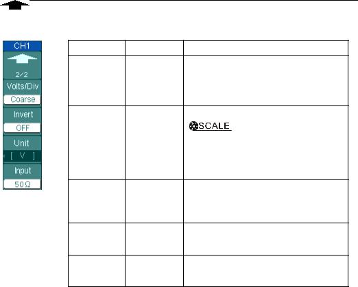
Figure 2-2 Table 2-2 The Channel menu (Page 2/2)
Menu |
Settings |
Comments |
Back to the previous menu page 2/2 (The followings are the same, no
more explanation).
|
|
Select the resolution of the |
|
|
Coarse |
knob. |
|
Volts/Div |
|
Define a 1-2-5 sequence. |
|
|
Fine |
To change the resolution to small |
|
|
|
steps between the coarse settings. |
|
|
ON |
Turn on the invert function. |
|
Invert |
OFF |
Restore to original display of the |
|
|
|
waveform. |
|
Unit |
V/ A/ W/ U |
Set “V”, “A”, “W” or “U” as the unit of |
|
|
vertical channel. |
||
|
|
||
Input |
50Ω* |
Press this key to select the input |
|
1MΩ |
resistance to 50Ω or 1MΩ. |
||
|
* For DS1202CA and DS1302CA only.
Copyright ©1998-2008 RIGOL Technologies, Inc. |
2-3 |
|
User’s Guide for DS1000CA Series |
|
|

RIGOL
1. Channel coupling
To use Channel 1 as an example, input a sine wave signal with DC shift.
Press CH1→Coupling→AC to set “AC” coupling. It will pass AC component blocks the DC component of the input signal.
The waveform is displayed as Figure 2-3:
 AC coupling setup
AC coupling status symbol
Figure 2-3
Waveform display
Press CH1→Coupling→DC, to set “DC” coupling. It will pass both AC and DC components of the input signal.
The waveform is displayed as Figure 2-4:
2-4 |
Copyright ©1998-2008 RIGOL Technologies, Inc. |
|
|
User’s Guide for DS1000CA Series |
|
 Loading...