


User’s Guide |
RIGOL |
Publication number DG1-070518
May 2007
DG1000 Series Function/Arbitrary
Waveform Generator
© Copyright RIGOL Technologies, Inc. 2007
All Rights Reserved

RIGOL
zCopyright © RIGOL TECHNOLOGIES, INC. 2007 All Rights Reserved.
zRIGOL products are protected by patent law in and outside of P.R. China.
zInformation in this publication replaces all the corresponding materials published previously.
zRIGOL Technologies, Inc. reserves the right to modify or change part of or all the specifications and pricing policies at company’s sole decision.
NOTE: RIGOL is the registered trademark of RIGOL TECHNOLOGIES, INC.
© Copyright RIGOL Technologies, Inc. 2007 |
I |
User’s Guide for DG1000 Series |
|

RIGOL
Safety Notices
Review the following safety precautions carefully before operating the instrument to avoid any personal injury or damage to the instrument or products connected to it.
To avoid potential hazards, use the instrument in the manner specified in this user’s guide.
The instrument should be serviced only by qualified personnel.
To Avoid Fire or Personal Injury
Use proper power line. Only the special power line of the products approved by the State should be used.
Insert or draw properly. Do not insert draw when the probe and the testing lead are connected with the power.
Ground the instrument. This generator is grounded through the protective terra conductor of the power cord. To avoid electric shock, the grounding conductor must be connected to the earth ground. Make sure that the instrument is properly grounded before connecting the input or output terminals.
Connect the probe properly. Connect the output terminal of the signal properly, make sure that the potential difference between the output terminal of the signal’s terra line and the earth is lower than 40V DC.
The probes’ ground terminals are at the same voltage level with the earth terminal of the instrument. Do not connect the ground terminals to a high voltage.
Observe All the Ratings of the Terminal. To avoid fire or shock, observe all the ratings and symbols that marked on the instrument. Read the user’s guide carefully before making connections to the instrument.
Do not operate without Covers. Do not operate your generator without covers or panels.
II |
© Copyright RIGOL Technologies, Inc. 2007 |
|
User’s Guide for DG1000 Series |

RIGOL
Use Proper Fuse. Only use the fuse type and rating specified for this product.
Avoid Circuit or Wire exposed. Do not touch the exposed connections or components when the power is turn-on.
Do not operate with suspected failures. If you suspect there is damage with this product, have it inspected by qualified service personnel authorized by RIGOL before further operations.
Provide Proper Ventilation.
Do not operate in wet/damp conditions.
Do not operate in an explosive atmosphere.
Keep the product’s surfaces clean and dry.
© Copyright RIGOL Technologies, Inc. 2007 |
III |
User’s Guide for DG1000 Series |
|
RIGOL
Safety Terms and Symbols
Terms in This Guide. These terms may appear in this manual:
WARNING: Warning statements indicate the conditions or practices that
!could result in injury or loss of life.
CAUTION: Caution statements indicate the conditions or practices that
!could result in damage to this product or other property.
Terms on the Product. These terms may appear on the product:
DANGER indicates an injury or hazard that may be immediately happen.
WARNING indicates an injury or hazard that may be not immediately happen.
CAUTION indicates that a potential damage to the instrument or other property might occur.
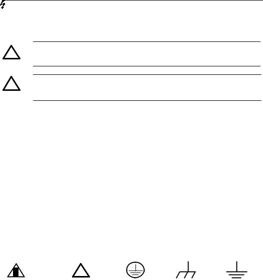
Symbols on the Product. These symbols may appear on the Instrument:
!
Hazardous |
Refer to the |
Protective |
Grounding |
Test |
Voltage |
Instructions |
earth terminal |
Terminal |
Grounding |
|
|
|
of Chassis |
Terminal |
IV |
© Copyright RIGOL Technologies, Inc. 2007 |
|
User’s Guide for DG1000 Series |

RIGOL
RIGOL DG1000 Generator at a Glance
This guide covers the following two types of DG1000 Series Function/ Arbitrary Waveform Generators:
DG1021 DG1011
RIGOL DG1000 Series Function/ Arbitrary Waveform Generator adopt the DDS technology, which can provide stable, high-precision, pure and low distortion sine signal. It can also provide 5MHz square waveform with fast rising and falling edges. Its combination of excellent system features, easiness in usage and versatile functions makes this generator a perfect solution for your job now and in the future.
DG1000 Series Function/ Arbitrary Waveform Generator have clear and simple Front-Panel. The user-friendly panel layout and instructions, versatile terminals, direct graph interface, built-in instructions and help system have greatly simplified the operation process, thus, users do not have to spend a great deal of time learning and familiarizing the operation of the generator before they can use it proficiently. The built-in AM, FM, PM and FSK modulating functions generate modulated waveform at ease, without the help of a separate modulating source. The USB I/O is the standard accessory.
From the characteristics and specifications given below, you will understand how DG1000 can satisfy your measurement requirements.
zDDS technology provides precise, stable and low distortion output signal.
z10 standard waveforms:
Sine, Square, Ramp, Pulse, Noise, Sinc, Exponential Rise, Exponential Fall, Cardiac and DC.
z100MSa/s sampling rate, enable to edit arbitrary waveform with 14-bit, 4K points.
zFrequency characteristics: Sine: 1µHz to 20 MHz Square: 1µHz to 5 MHz Ramp: 1µHz to 150 kHz Pulse: 500µHz to 3MHz
White Noise 5MHz bandwidth (-3dB)
Arbitrary waveform 1μHz to 5MHz
© Copyright RIGOL Technologies, Inc. 2007 |
V |
User’s Guide for DG1000 Series |
|

RIGOL
zAmplitude range 2mVPP to 10VPP (50 Ω)
4mVPP to 20VPP (High Z)
zAbundant modulation function, various modulated waveform: AM, FM, PM and FSK.
zLinear, logarithm Sweep and Burst mode.
zAbundant I/O: External Modulation Source, External 10 MHz Reference Input, External trigger source, waveform output, synchronous digital signal output, Internal 10 MHz Reference output.
zSupport USB storage device. Could store and read waveform configure parameters or the edited arbitrary waveform with USB devices. System Updating could also be performed by using USB devices.
zStandard interface: USB Host & Device
zGraph interface which shows the signal setting directly.
zMultilanguage user interface.
zEmbedded Chinese/ English Help System.
zSupport Chinese/ English Input.
Notice:
All the indexes described in this guide are according to DG1021, if you need to know the particular specifications about the other type, please look over “Appendix A” in Chapter 6.
VI |
© Copyright RIGOL Technologies, Inc. 2007 |
|
User’s Guide for DG1000 Series |

RIGOL
Content
Safety Notices ...................................................................................................................... |
II |
RIGOL DG1000 Generator at a Glance........................................................................... |
V |
Chapter 1 Getting Started...................................................................................... |
1-1 |
General Inspection ........................................................................................................... |
1-2 |
Handle Adjustment........................................................................................................... |
1-3 |
The Front/Rear Panel....................................................................................................... |
1-4 |
The DG1000 User Interface ............................................................................................ |
1-7 |
To Set a Waveform .......................................................................................................... |
1-8 |
To Set Modulate/ Sweep/Burst..................................................................................... |
1-11 |
To Set Trigger/Output ................................................................................................... |
1-13 |
To Use Digital Input ....................................................................................................... |
1-14 |
To Use Store/Utility/Help Function............................................................................... |
1-15 |
Chapter 2 Operating Your Generator................................................................. |
2-1 |
The Menu/Graph Mode.................................................................................................... |
2-2 |
To Set Sine Signals........................................................................................................... |
2-3 |
To Set Square Signals...................................................................................................... |
2-7 |
To Set Ramp Signals...................................................................................................... |
2-10 |
To Set Pulse Signals....................................................................................................... |
2-12 |
To Set Noise Signals....................................................................................................... |
2-14 |
To Set Arbitrary Signals................................................................................................. |
2-15 |
To Set Counter................................................................................................................ |
2-27 |
To Generate the Modulated Waveform....................................................................... |
2-32 |
To Generate Sweep........................................................................................................ |
2-41 |
To Generate Burst .......................................................................................................... |
2-44 |
To Store and Recall ........................................................................................................ |
2-49 |
To Set the Utility Function............................................................................................. |
2-56 |
How to Use the Built-in Help System........................................................................... |
2-74 |
Chapter 3 Application & Examples ..................................................................... |
3-1 |
Example 1: To Generate a Sine Wave ........................................................................... |
3-1 |
Example 2: To generate a Square Wave....................................................................... |
3-2 |
Example 3: To generate a Ramp Wave ......................................................................... |
3-3 |
Example 4: To generate a Pulse Wave .......................................................................... |
3-4 |
Example 5: To Generate a Noise Wave ......................................................................... |
3-5 |
© Copyright RIGOL Technologies, Inc. 2007 |
VII |
User’s Guide for DG1000 Series |
|

RIGOL
Example 6: To generate Arbitrary Waveform ............................................................... |
3-6 |
Example 7: To Generate an Arbitrary Waveform ......................................................... |
3-7 |
Example 8: To Generate an AM Waveform ................................................................... |
3-9 |
Example 9: To Generate an FSK Waveform................................................................ |
3-11 |
Example 10: To generate a Linear Sweep Waveform................................................ |
3-13 |
Example 11: To generate a Burst Waveform.............................................................. |
3-15 |
Example 12: To measure the frequency...................................................................... |
3-17 |
Chapter 4 Prompt messages & troubleshooting............................................ |
4-1 |
Prompting Messages ........................................................................................................ |
4-1 |
Troubleshooting .............................................................................................................. |
4-18 |
Chapter 5 Support & Service................................................................................. |
5-1 |
Chapter 6 Appendix.................................................................................................. |
6-1 |
Appendix A Specifications................................................................................................ |
6-1 |
Appendix B DG1000 Series Accessories ........................................................................ |
6-9 |
Appendix C General Care and Cleaning....................................................................... |
6-10 |
VIII |
© Copyright RIGOL Technologies, Inc. 2007 |
|
User’s Guide for DG1000 Series |
RIGOL
Chapter 1 Getting Started
This chapter covers the following topics:
General Inspection
To Adjust the Handle
The Front/rear Panel of DG1000 Series
The User Interface of DG1000 Series
To Set a Waveform
To Set Modulation/Sweep/Burst
To Set Trigger/Output and Counter
To Use Digital Input
To Use Store/Utility/Help Function
© Copyright RIGOL Technologies, Inc. 2007 |
1-1 |
User’s Guide for DG1000 Series |
|

RIGOL
General Inspection
When you get a new DG1000 Series Function/ Arbitrary Waveform Generator, you are suggested to take the following steps to inspect the instrument.
1.Inspect the shipping container for damage.
If there are damages in the packing or foam, keep them until he whole machine and the accessories passing the electric and mechanical testing.
2.Check the accessories.
Accessories supplied with the instrument are listed in chapter 6"Appendix B: DG1000 Series Accessories". If the contents are incomplete or damaged, please contract the local selling representative of RIGOL.
3.Inspect the instrument.
In case any mechanical damage or defect, or if the instrument does not operate properly or pass performance tests, notify your RIGOL Sales Representative. If the shipping container is damaged, or the cushioning materials show signs of stress, notify the carrier of your RIGOL sales office. Keep the shipping materials for the carrier’s inspection. RIGOL offices will arrange for repair or replacement at RIGOL’s option without waiting for claim settlement.
1-2 |
© Copyright RIGOL Technologies, Inc. 2007 |
|
User’s Guide for DG1000 Series |

RIGOL
Handle Adjustment
To adjust the handle position of DG1000 Function/ Arbitrary Waveform Generator, please grip the handle by the sides and pull it outward. Then, make the handle rotate to the desired position. The operating methods are shown below in graphs 1-1 and 1-2.
Figure 1-1 The method of adjusting the handle
Figure 1-2 Adjustable Positions
© Copyright RIGOL Technologies, Inc. 2007 |
1-3 |
User’s Guide for DG1000 Series |
|
RIGOL
The Front/Rear Panel
When you get a new DG1000 Series Function/ Arbitrary Waveform Generator, first you need to know how to operate the front/ Rear panel correctly. This chapter will make a brief introduction and description for the operation and functions of the Front/ Rear Panel.
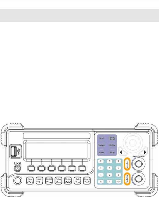
The Front Panel at a Glance
DG1000 Series Function/ Arbitrary Waveform Generator has clear and simple front panel. See Figure 1-3 and Figure 1-4. The Front Panel has a knob, functional keys and menu buttons. The 6 grey buttons below the screen are menu buttons, by using which you can choose different options on the current menu. The rests are the functional keys, with which you can enter different function menus or obtain specific functional applications directly.
Figure 1-3
Front Panel for DG1000 Series
1-4 |
© Copyright RIGOL Technologies, Inc. 2007 |
|
User’s Guide for DG1000 Series |

RIGOL
Figure 1-4
Front Panel Operation Instruction for DG1000 Series
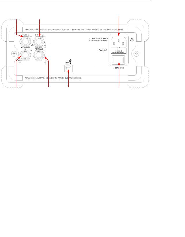
The Rear Panel at a Glance
Figure 1-5
Rear Panel for DG1000 Series
© Copyright RIGOL Technologies, Inc. 2007 |
1-5 |
User’s Guide for DG1000 Series |
|
RIGOL
Figure 1-6
Rear Panel Operation Instruction for DG1000 Series
1-6 |
© Copyright RIGOL Technologies, Inc. 2007 |
|
User’s Guide for DG1000 Series |
RIGOL
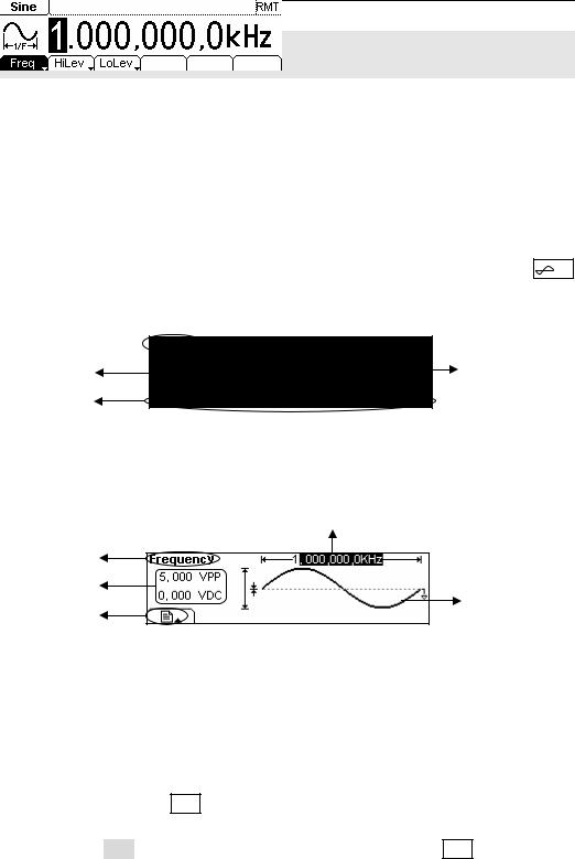
The DG1000 User Interface
DG1000 Series Function/ Arbitrary Waveform Generator provide two Display modes: Menu and Graph. Under the Menu Display mode, the display interface is divided into 4 parts: state, waveform icon, operation menu, and parameter display. See Figure 1-7. Under the Graph display mode, you can check the current waveform parameters in the graphics. The display interface is also divided into 4 parts: state, parameter display, display menu button and waveform display. See Figure 1-8. The operation menu will appear at the bottom of the screen when you press any menu button. These two display modes can be switched to each other by pressing the /A button.
State
Waveform |
Parameter |
Operation
Menu
Figure 1-7
The menu Display Mode Interface Instruction
|
Parameter |
|
|
Display |
|
State |
|
|
Parameters |
Waveform |
|
Display Menu |
||
Display |
||
button |
|
Figure 1-8
Graph Mode Display Interface Instruction
Note
The signs for the buttons in this guide are the same as the panel buttons. Please note that the signs for the functional buttons on the operation panel are represented by squared words, such as Sine, which represents the transparent functional key with Sine on it on the front panel, while the menu buttons are represented by shadow words such as Freq, which means the “Frequency” option in the Sine menu.
© Copyright RIGOL Technologies, Inc. 2007 |
1-7 |
User’s Guide for DG1000 Series |
|
RIGOL
To Set a Waveform
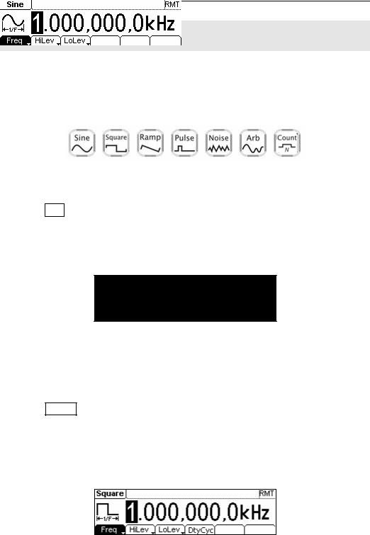
At the left of the operation panel, there is a set of buttons with waveform icon. See Figure 1-9. The exercise below will help you to be familiar with the waveform selection settings. The instructions of the waveform setting are all carried out in the Menu Display Mode.
Figure 1-9
Waveform Selection Buttons
1.Press Sine button, and the waveform icon turns into Sine with a “Sine” typeface in the state area. DG1000 Series Generator can generate Sine signal with frequency from 1μHz to 20MHz. By setting Frequency/Period, Amplitude/ High Level, Offset/ Low level, sine signal with different parameters can be generated.
Figure 1-10
Sine Signal in the Menu Display Mode
As shown in Figure 1-10, the default signal parameters are: 1kHz Frequency, 5.0 VPP Amplitude and 0 VDC Offset.
2.Press Square button, and the waveform icon turns into Square with a “Square” typeface in the state area. DG1000 Series Generator can generate Square signal with frequency from 1μHz to 5MHz and variable duty cycle. By setting Frequency/Period, Amplitude/ High Level, Offset/ Low level, and Duty Cycle, Square signal with different parameters can be generated.
Figure 1-11
Square Signal in the Menu Display Mode
1-8 |
© Copyright RIGOL Technologies, Inc. 2007 |
|
User’s Guide for DG1000 Series |
RIGOL
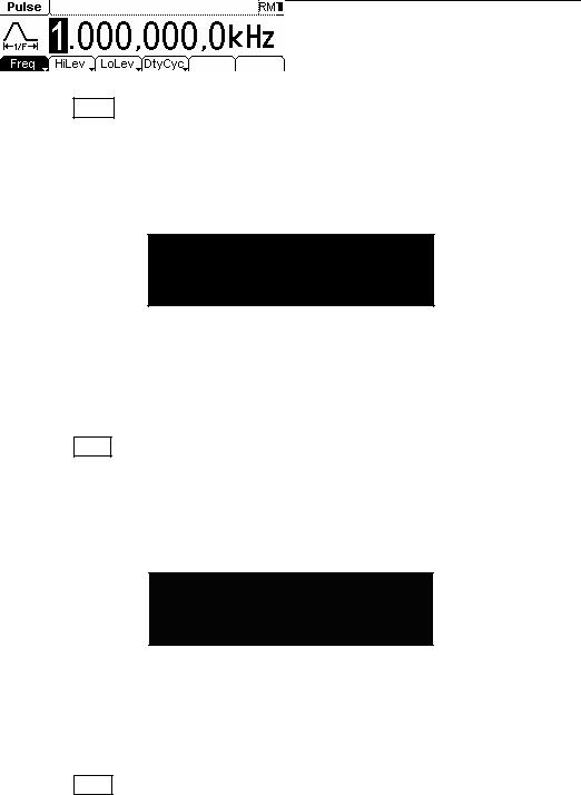
As shown in Figure 1-11, the default signal parameters are: 1kHz Frequency, 5.0 VPP Amplitude, 0 VDC Offset and 50% Duty Cycle.
3.Press Ramp button, and the waveform icon turns into Ramp with a “Ramp” typeface in the state area. DG1000 Series Generator can generate Ramp signal with frequency from 1μHz to 150 kHz and variable Symmetry. By setting Frequency/Period, Amplitude/ High Level, Offset/ Low level, and Symmetry, Ramp signal with different parameters can be generated.
Figure 1-12
Ramp Signal in the Menu Display Mode
As shown in Figure 1-12, the default signal parameters are: 1kHz Frequency, 5.0 VPP Amplitude, 0 VDC Offset and 50% Symmetry.
4.Press Pulse button, and the waveform icon turns into Pulse with a “Pulse” typeface in the state area. DG1000 Series Generator can generate Pulse signal with frequency from 500μHz to 3MHz and variable Pulse Width. By setting Frequency/Period, Amplitude/ High Level, Offset/ Low level, Pulse Width and Duty Cycle, Pulse signal with different parameters can be generated.
Figure 1-13
Pulse Signal in the Menu Display Mode
As shown in Figure 1-13, the default signal parameters are: 1kHz Frequency, 5.0 VPP Amplitude, 0 VDC Offset, 200μs Pulse Width.
5.Press Noise button, and the waveform icon turns into Noise with a “Noise” typeface in the state area. DG1000 Series Generator can generate Noise signal with Band Width up to 5MHz. By setting Amplitude/ High Level, Offset/ Low level, Noise signal with different parameters can be generated.
© Copyright RIGOL Technologies, Inc. 2007 |
1-9 |
User’s Guide for DG1000 Series |
|

RIGOL
Figure 1-14
Noise Signal in the Menu Display Mode
As shown in Figure 1-14, the default signal parameters are: 5.0 VPP Amplitude and 0 VDC Offset.
6.Press Arb button, and the waveform icon turns into Arb with an “Arb” typeface in the state area. DG1000 Series Generator can generate repeatable arbitrary waveform signals with at most 4K points and 3MHz frequency. By setting Frequency/Period, Amplitude/ High Level, Offset/ Low level, arbitrary waveform signals with different parameters can be generated.
Figure 1-15
Arbitrary waveform Signal in the Menu Display Mode
As shown in Figure 1-15, the default Exponential Rise Signal parameters are: 1kHz Frequency, 5.0 VPP Amplitude and 0 VDC Offset.
7.Press Count button, and the waveform icon turns into Arb with an “Count” typeface in the state area. Select “Freq”, “Period”, “PWidth”, “NWidth”, the screen will display corresponding measure result. Select “Setup” to set the parameters of input coupling method, sensitivity, trigger level and high frequency on/off.
Figure 1-16
General interface of the counter
1-10 |
© Copyright RIGOL Technologies, Inc. 2007 |
|
User’s Guide for DG1000 Series |
RIGOL
To Set Modulate/ Sweep/Burst
As shown in Figure 1-17, there are three buttons on the front panel, which are used for Modulating, sweeping and bursting settings. The instructions below will help you familiarize with the setting of these functions.
Figure 1-17
Modulate/ Sweep/ Burst button
1.Press Mod button, and a Modulated waveforms will be generated.
Parameters are set by using the menu buttons. The modulated waveform can be changed by changing the parameters such as Type, Internal/external Modulation, Depth, Frequency, Waveform, etc.
DG1000 Series can modulate waveform using AM, FM, PM and FSK. Sine, Square, Ramp or Arbitrary waveforms can be modulated (Pulse, Noise and DC cannot be modulated).
Figure 1-18
Modulated Waveform Signal in the Menu Display Mode
2.Press Sweep button, Sine, Square, Ramp or Arbitrary waveform can be swept (Pulse, Noise and DC can not be swept).
In the Sweep Mode, DG1000 Series generate signal with variable frequencies.
© Copyright RIGOL Technologies, Inc. 2007 |
1-11 |
User’s Guide for DG1000 Series |
|
RIGOL
Figure 1-19
Sweep Waveform Signal in the Menu Display Mode
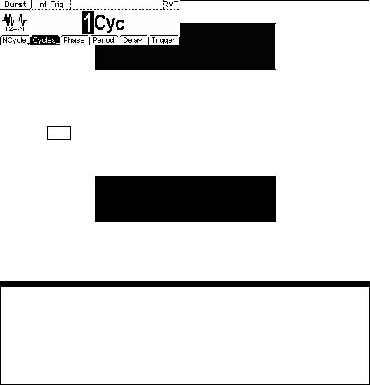
3.Press Burst button, Burst for Sine, Square, Ramp, Pulse or Arbitrary waveform can be generated (Noise can only be used in the gated Burst).
Figure 1-20
Burst Waveform Signal in the Menu Display Mode
Term Explanation
Burst Output Waveforms with set cycle times
Burst can last for certain times of waveform cycle (N-Cycle Burst) or be controlled by external gated signals (Gated Burst). Burst applies to all kinds of waveforms, but noise can only be used in gated burst.
1-12 |
© Copyright RIGOL Technologies, Inc. 2007 |
|
User’s Guide for DG1000 Series |
RIGOL
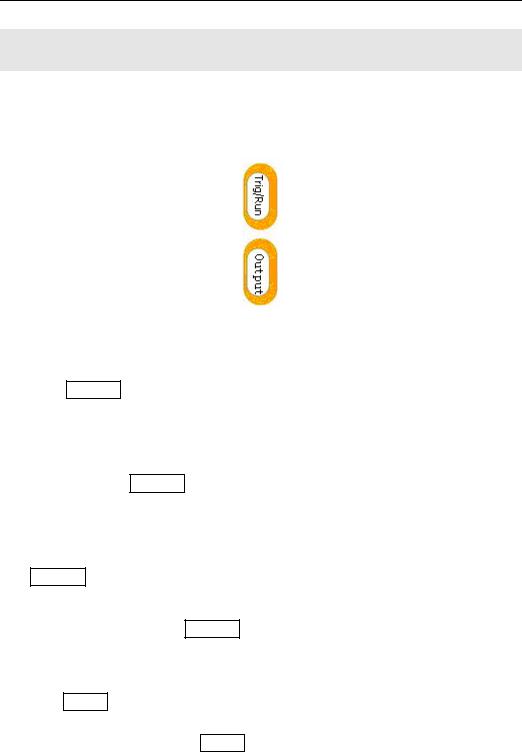
To Set Trigger/Output
As shown in Figure 1-21, there are two buttons on the right side of the operation panel, which are used to set Trigger and Output Control. The instruction below will help you to be familiar with these functions.
Figure 1-21
Trigger/ Output Button
1.Press Trig/Run Button, choose internal/ external or manual Trigger (Manual Trigger can only be used in Sweep and N-Cycle Burst)
The default setting for Trigger is “Internal”. In this mode, when the Sweep or Burst Mode is also selected, the Generator will continuously generate burst. At this time, press Trig/Run button, the instrument will shift from the “Automatic” Trigger mode into “Manual” Trigger mode.
When the generator uses the” External” Trigger Mode, if the Sweep or the Burst Mode is selected, signal will be continuously generated. At this time, press Trig/Run button, the instrument state will not change, and it will show “The instrument has already been triggered”.
Every time you press the Trig/Run button, “Manual” Trigger will start a sweep or generate a burst. Press the button again, and the generator will be triggered again.
2. Press Output Button, activate or deactivate the output signal.
If an overload message is shown, disconnect the external equipment from the output terminals and press Output button, reactivate the output terminal.
© Copyright RIGOL Technologies, Inc. 2007 |
1-13 |
User’s Guide for DG1000 Series |
|

RIGOL
To Use Digital Input
As shown in Figure 1-22, there are two groups of buttons on the operation panel, which are direction button, the knob and the keypad. The instruction below will help you to be familiar with the Digital Input Function.
(1) Direction Key and the Knob |
(2) Keyboard |
Figure 1-22
Front Panel Digital Input
1.Use the Direction keys to move the cursor left or right. Rotate the knob to change a digit (clockwise to increase).
2.Use the Keypad to set the parameters values of the waveforms, which can change its value directly.
1-14 |
© Copyright RIGOL Technologies, Inc. 2007 |
|
User’s Guide for DG1000 Series |
RIGOL
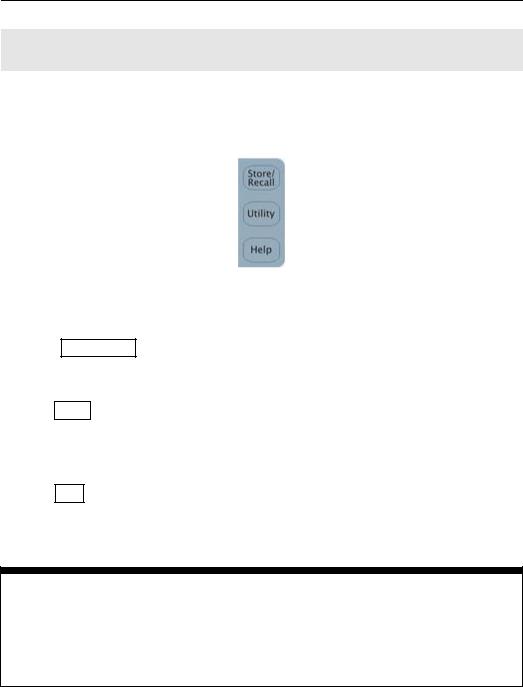
To Use Store/Utility/Help Function
As shown in Figure 1-23, there are three buttons on the operation panel, which are used to call the store/recall, utility and help function. The instruction below will help you to be familiar with these Functions.
Figure 1-23
Store/Recall, Utility and Help Button
1.The Store/Recall Button is used to store waveform data and configure information.
2.The Utility Button is used to set the auxiliary system function, change the output configure parameters, interface setting, system setting information or perform the instrument self-test and read the calibration information, etc.
3.The Help Button is used to read the help information.
Operation Instruction
To get help
To get help on any key of the front panel, press the key and last for 1 second, then the help message will appear.
© Copyright RIGOL Technologies, Inc. 2007 |
1-15 |
User’s Guide for DG1000 Series |
|

RIGOL
Chapter 2 Operating Your Generator
By now you have got a brief understanding of DG1000 series with the front/rear panel, every function control area and keys. You should also know how to set your function/ arbitrary waveform generator. If you are not familiar with these operations, please read Chapter 1 “Getting Started” again.
This chapter covers the following topics:
|
Menu/Graph Mode |
( |
|
|
/A |
) |
|
|
|
|||||||||
|
Setting Sine Signal |
( |
|
|
|
|
|
|
|
|
|
|
|
|
|
|
|
|
|
|
|
Sine |
) |
|
|
|
|
||||||||||
|
Setting Square Signal |
( |
|
|
|
|
|
|
|
|
|
|
|
|
|
|||
|
|
|
Square |
) |
|
|||||||||||||
|
Setting Ramp Signal |
( |
|
|
|
|
|
|
|
|
|
|
|
|
|
|||
|
|
|
Ramp |
) |
|
|
||||||||||||
|
Setting Pulse Signal |
( |
|
|
|
|
|
|
|
|
|
|
|
|
|
|||
|
|
|
Pulse |
) |
|
|
||||||||||||
|
Setting Noise Signal |
( |
|
|
|
|
|
|
|
|
|
|
|
|
|
|||
|
|
|
Noise |
) |
|
|
||||||||||||
|
Setting Arb Signal |
( |
|
|
|
|
|
|
|
|
|
|
|
|
||||
|
|
|
Arb |
) |
|
|
|
|
|
|
|
|
||||||
|
Setting counter |
( |
|
|
|
|
|
|
|
) |
|
|
||||||
|
Count |
|||||||||||||||||
|
|
|
|
|
|
|
|
|
|
|
|
|
||||||
|
Output Modulated Signal |
|
|
( |
Mod |
) |
|
|
|
|||||||||
|
|
|
|
|
|
|
|
|
|
|
|
|
||||||
|
Output Sweep Signal |
|
|
( |
Sweep |
) |
|
|
||||||||||
|
|
|
|
|
|
|
|
|
|
|
||||||||
|
Output Burst Signal |
|
|
( |
Burst |
|
) |
|
|
|||||||||
Trigger Sweep or Burst |
( |
|
|
|
|
|
) |
|
||||||||||
|
Trig/Run |
|||||||||||||||||
|
|
|
|
|
|
|
||||||||||||
|
Store/Recall |
( |
Store/Recall |
) |
||||||||||||||
|
|
|
|
|
||||||||||||||
|
Utility Setting |
( |
Utility |
|
) |
|||||||||||||
|
|
|
|
|||||||||||||||
|
Help System |
( |
Help |
) |
||||||||||||||
You are suggested to read this chapter carefully so as to understand DG1000 Series Generator’s versatile waveform setting Functions and the other operation methods.
© Copyright RIGOL Technologies, Inc. 2007 |
2-1 |
|
User’s Guide for DG1000 Series |
|
|
RIGOL
The Menu/Graph Mode
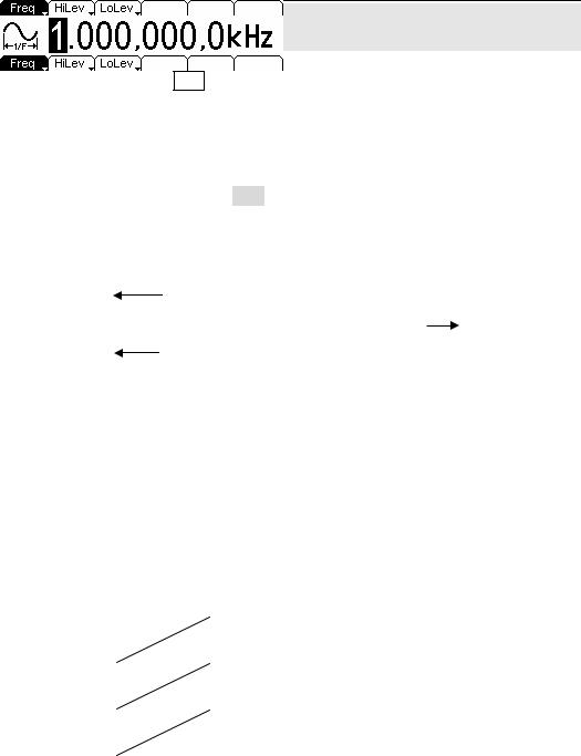
To activate the Graph Mode
Press /A, enter the Graph Mode. The name of the current selection parameter is shown on the top left corner of the screen, and its value is shown in inverse color. See Figure 2-1.
Display Menu
Button
Figure 2-1
Graph Mode Interface
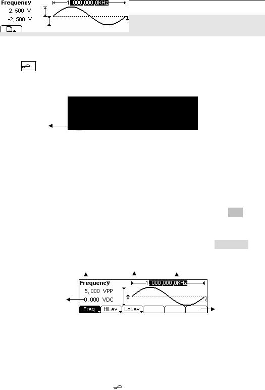
To Select the Desired Parameter
To select the specific parameters, please press any menu button and the operation menu will pop out. Press the corresponding button to set the parameter. For example, if you want to change the frequency, press any menu button and select Freq menu. The direction button will help you find your desired parameter digit and change its value with the knob or the keypad, see Figure 2-2. In the Graph Mode, the parameters will still switch at a second press on the button, such as Amp/HiLev.
Current |
Output waveform Frequency |
Parameter |
Amp 
Offset
Operation
Menu
Figure 2-2
Setting the parameters in the Graph Mode
To Quit the Graph Mode
To quit the Graph Mode, press the |
/ A |
and return the Menu Mode. |
2-2 |
© Copyright RIGOL Technologies, Inc. 2007 |
|
|
User’s Guide for DG1000 Series |
|
RIGOL
To Set Sine Signals
In the Menu Mode, press Sine Key to call the Sine operation. The top left corner of the screen will show the name of the current waveform, see Figure 2-3. The output Sine waveform parameters are set using the Sine operation menu.
The parameters for Sine waveforms are: Frequency/ Period, Amplitude/ High Level, Offset/ Low Level. Different Sine Signals are generated by using these parameters. As is shown in Figure 2-4, select Freq in the operation menu and the frequency parameter will show in the parameter area. Users then can change the frequency by using the direction button and the knob or the keypad.
|
Output |
|
|
|
|
|
|
|
|
|
|
|
|
||
|
Waveform |
|
|
|
|
|
Current |
|
|
|
|
|
|
|
|
Operation Menu: |
|
|
|
|
|
Parameter |
|
Controlled and |
|
|
|
|
|
|
|
|
|
|
|
|
|
||
Operated by menu |
|
|
|
|
|
|
|
|
button |
|
|
|
|
|
|
|
|
Figure 2-3 Sine Signal Parameter Setting Interface |
|||||
|
|
|
|
|
|
||
|
|
|
|
|
|
|
|
|
|
|
|
Figure 2-4 Operation Menu |
|||
Table 2-1 Operation Menu for Sine Signal |
|||||||
|
|
|
|
|
|
|
|
|
Function |
Settings |
|
Explanation |
|||
|
Menu |
|
|||||
|
|
|
|
|
|
|
|
|
Frequency/ |
|
|
|
Setting the signal’s frequency or period; the |
||
|
Period |
|
|
|
current parameter will switch at a second press. |
||
|
|
|
|
|
|
||
|
Amplitude/ |
|
|
|
Setting the signal’s Amplitude or High Level; the |
||
|
High Level |
|
|
|
current parameter will switch at a second press. |
||
|
|
|
|
|
|
||
|
Offset/Low |
|
|
|
Setting the signal’s Offset or Low Level; the |
||
|
Level |
|
|
|
current parameter will switch at a second press |
||
|
|
|
|
|
|
|
|
© Copyright RIGOL Technologies, Inc. 2007 |
2-3 |
|
User’s Guide for DG1000 Series |
|
|
RIGOL
To Set the Output Frequency/Period
(1) Press Sine Æ Freq/Period Æ Freq, to set the frequency parameter.
The frequency shown on the screen is the default value when the instrument is powered or the set value beforehand. When setting the function, if the current value is valid for the new waveform, it will be used sequentially. If you want to set the period for the waveform, press Freq/Period button again, switch to the Period parameter (The current operation is displayed in inverse color).
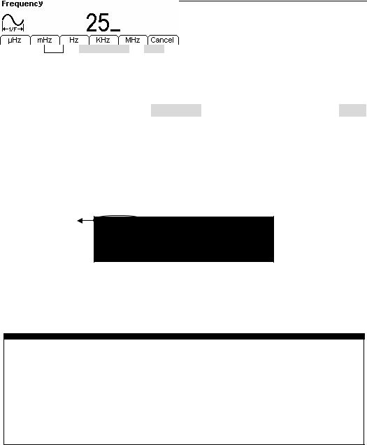
(2) Input the desired frequency.
Use the keypad to input the parameter value directly, and press the corresponding button to select the parameter unit. Or you can use the direction button to select the digit you want to edit, and then use the knob to change its value.
Current Parameter:
Frequency
Figure 2-5 Setting the Frequency
Instruction:
When using the keypad to enter the digit, you can use the Left direction button to move the cursor backward and delete or change the value of the previous digit. When using the knob to input, use the direction buttons to select the digit you want to edit and rotate the knob to change its value.
2-4 |
© Copyright RIGOL Technologies, Inc. 2007 |
|
|
User’s Guide for DG1000 Series |
|
 Loading...