


 Loading...
RIGOL
User’s Guide
DG900 Series
Function/Arbitrary Waveform
Generator
Aug. 2018
RIGOL (SUZHOU) TECHNOLOGIES INC.

RIGOL
Guaranty and Declaration
Copyright
© 2018 RIGOL (SUZHOU) TECHNOLOGIES INC. All Rights Reserved.
Trademark Information
RIGOL is a registered trademark of RIGOL (SUZHOU) TECHNOLOGIES INC.
Publication Number
UGB10100-1110
Software Version
00.00.01
Software upgrade might change or add product features. Please acquire the latest version of the manual from RIGOL website or contact RIGOL to upgrade the software.
Notices
RIGOL products are covered by P.R.C. and foreign patents, issued and pending.
RIGOL reserves the right to modify or change parts of or all the specifications and pricing policies at the company’s sole decision.
Information in this publication replaces all previously released materials.
Information in this publication is subject to change without notice.
RIGOL shall not be liable for either incidental or consequential losses in connection with the furnishing, use, or performance of this manual, as well as any information contained.
Any part of this document is forbidden to be copied, photocopied, or rearranged without prior written approval of RIGOL.
Product Certification
RIGOL guarantees that this product conforms to the national and industrial standards in China as well as the ISO9001:2015 standard and the ISO14001:2015 standard. Other international standard conformance certifications are in progress.
Contact Us
If you have any problem or requirement when using our products or this manual, please contact RIGOL.
E-mail: service@rigol.com Website: www.rigol.com
DG900 User's Guide |
I |

RIGOL
Safety Requirement
General Safety Summary
Please review the following safety precautions carefully before putting the instrument into operation so as to avoid any personal injury or damage to the instrument and any product connected to it. To prevent potential hazards, please follow the instructions specified in this manual to use the instrument properly.
Use the BNC Output Connector Properly.
The BNC output connector on the front panel only allows to output the signal but not to input the signal.
Use Proper Power Cord.
Only the exclusive power cord designed for the instrument and authorized for use within the local country could be used.
Ground the Instrument.
The instrument is grounded through the Protective Earth lead of the power cord. To avoid electric shock, connect the earth terminal of the power cord to the Protective Earth terminal before connecting any input or output terminals.
Connect the Probe Correctly.
If a probe is used, the probe ground lead must be connected to earth ground. Do not connect the ground lead to high voltage. Improper way of connection could result in dangerous voltages being present on the connectors, controls or other surfaces of the oscilloscope and probes, which will cause potential hazards for operators.
Observe All Terminal Ratings.
To avoid fire or shock hazard, observe all ratings and markers on the instrument and check your manual for more information about ratings before connecting the instrument.
Use Proper Overvoltage Protection.
Ensure that no overvoltage (such as that caused by a bolt of lightning) can reach the product. Otherwise, the operator might be exposed to the danger of an electric shock.
Do Not Operate Without Covers.
Do not operate the instrument with covers or panels removed.
Do Not Insert Objects Into the Air Outlet.
Do not insert objects into the air outlet, as doing so may cause damage to the instrument.
II |
DG900 User's Guide |

RIGOL
Use Proper Fuse.
Please use the specified fuses.
Avoid Circuit or Wire Exposure.
Do not touch exposed junctions and components when the unit is powered on.
Do Not Operate With Suspected Failures.
If you suspect that any damage may occur to the instrument, have it inspected by RIGOL authorized personnel before further operations. Any maintenance, adjustment or replacement especially to circuits or accessories must be performed by RIGOL authorized personnel.
Provide Adequate Ventilation.
Inadequate ventilation may cause an increase of temperature in the instrument, which would cause damage to the instrument. So please keep the instrument well ventilated and inspect the air outlet and the fan regularly.
Do Not Operate in Wet Conditions.
To avoid short circuit inside the instrument or electric shock, never operate the instrument in a humid environment.
Do Not Operate in an Explosive Atmosphere.
To avoid personal injuries or damage to the instrument, never operate the instrument in an explosive atmosphere.
Keep Product Surfaces Clean and Dry.
To avoid dust or moisture from affecting the performance of the instrument, keep the surfaces of the instrument clean and dry.
Prevent Electrostatic Impact.
Operate the instrument in an electrostatic discharge protective environment to avoid damage induced by static discharges. Always ground both the internal and external conductors of cables to release static before making connections.
Use the Battery Properly.
Do not expose the battery (if available) to high temperature or fire. Keep it out of the reach of children. Improper change of a battery (lithium battery) may cause an explosion. Use the RIGOL specified battery only.
Handle with Caution.
Please handle with care during transportation to avoid damage to keys, knobs, interfaces, and other parts on the panels.
DG900 User's Guide |
III |
RIGOL
Safety Notices and Symbols
Safety Notices in this Manual:
WARNING
Indicates a potentially hazardous situation or practice which, if not avoided, will result in serious injury or death.
CAUTION
Indicates a potentially hazardous situation or practice which, if not avoided, could result in damage to the product or loss of important data.
Safety Terms on the Product:
DANGER
WARNING
CAUTION
Safety Symbols on the Product:
Hazardous |
Safety Warning |
Protective Earth |
Chassis Ground |
Test Ground |
Voltage |
|
Terminal |
|
|
IV |
DG900 User's Guide |
RIGOL
Care and Cleaning
Care
Do not store or leave the instrument where it may be exposed to direct sunlight for long periods of time.
Cleaning
Clean the instrument regularly according to its operating conditions.
1.Disconnect the instrument from all power sources.
2.Clean the external surfaces of the instrument with a soft cloth dampened with mild detergent or water. Avoid having any water or other objects into the chassis via the heat dissipation hole. When cleaning the LCD, take care to avoid scarifying it.
CAUTION
To avoid damage to the instrument, do not expose it to caustic liquids.
WARNING
To avoid short-circuit resulting from moisture or personal injuries, ensure that the instrument is completely dry before connecting it to the power supply.
Environmental Considerations
The following symbol indicates that this product complies with the WEEE Directive 2002/96/EC.
Product End-of-Life Handling
The equipment may contain substances that could be harmful to the environment or human health. To avoid the release of such substances into the environment and avoid harm to human health, we recommend you to recycle this product appropriately to ensure that most materials are reused or recycled properly. Please contact your local authorities for disposal or recycling information.
You can log in to RIGOL official website (www.rigol.com) to download the latest version of the RoHS-WEEE certification file.
DG900 User's Guide |
V |

RIGOL
DG900 Series Function/Arbitrary
Waveform Generator Overview
As a multi-functional signal generator, DG900 series function/arbitrary waveform generator integrates many instruments into 1, such as function generator, arbitrary waveform generator, noise generator, pulse generator, harmonic generator, analog/digital modulator, and frequency counter. As a multi-functional and portable instrument, it offers you a new choice in education, R&D, production, measurement, and other industries with its user-friendly touch screen and high performance at an unprecedented price point.
Main Features:
Unique SiFi II (Signal Fidelity II) technology: generate the arbitrary waveforms point by point; recover the signal without distortion; sample rate accurate and adjustable; jitter of all the output waveforms (including Sine, Pulse, etc.) as low as 200 ps
16 Mpts memory depth per channel for arbitrary waveforms
Standard dual-channel with the same performance, equivalent to two independent signal sources
High frequency stability: ±1 ppm; low phase noise: -105 dBc/Hz
Built-in up to 8 orders harmonics generator
Built-in 7 digits/s, 240 MHz bandwidth full featured frequency counter
Up to 160 built-in arbitrary waveforms, covering the common signals in engineering application, medical electronics, auto electronics, math processing, and other various fields
Sample rate up to 250 MSa/s, vertical resolution 16 bits
Arbitrary waveform sequence editing function available; arbitrary waveforms also can be generated through the PC software
Various analog and digital modulation functions: AM, FM, PM, ASK, FSK, PSK, and PWM.
Standard waveform combine function, capable of outputting specified waveforms combined with the basic waveforms
Standard channel tracking function, when enabled, all the parameters of both channels are updated based on users' configurations
USB HOST&DEVICE interface (standard); USB-GPIB function supported
4.3'' TFT color touch screen
RS232, PRBS, and Dualtone outputs supported
VI |
DG900 User's Guide |

RIGOL
Document Overview
Main Topics in this Manual
Chapter 1 Quick Start
Chapter 2 Front Panel Operations
Chapter 3 Remote Control
Chapter 4 Troubleshooting
Chapter 5 Appendix
Introduces the appearance and dimensions of
DG900, its front/rear panel, and user interface.
Introduces the main functions and operation methods of DG900.
Introduces how to control DG900 remotely. Lists the possible failures and solutions in using
DG900.
Provides the information about the options and accessories list, as well as warranty information of DG900.
Format Conventions in this Manual
1.Keys:
The keys on the front panel are usually denoted by the format of "Key Name (Bold) + Text Box". For example, Utility denotes the Utility key.
2.Menu Labels:
The menu labels are usually denoted by the format of "Menu Word (Bold) + Character Shading". For example, System Setting.
3.Connectors:
The connectors on the front or rear panel are usually denoted by the format of "Connector Name (Bold) + Square Brackets (Bold)". For example, [Counter].
4.Operation Procedures:
"" represents the next step of operation. For example, Utility System Setting denotes that first press Utility on the front panel, and then tap the
System Setting menu label.
Content Conventions in this Manual
1. DG900 series function/arbitrary waveform generator includes the following models: This manual takes DG992 as an example to illustrate the operation methods of the DG900 series.
Model |
No. of Channels |
Max. Output Frequency |
DG952 |
2 |
50 MHz |
DG972 |
2 |
70 MHz |
DG992 |
2 |
100 MHz |
2. DG900 series function/arbitrary waveform generator is equipped with two channels (CH1 and CH2). Unless otherwise specified, this manual takes CH1 as
DG900 User's Guide |
VII |

RIGOL
an example to introduce the operation methods of the generator. The operation methods of CH2 is the same as that of CH1.
Manuals of this Product
The manuals of this product mainly include the quick guide, user’s guide, programming guide, data sheet, and etc. For the latest version of this manual, download it from the official website of RIGOL (www.rigol.com).
VIII |
DG900 User's Guide |
Contents |
RIGOL |
Contents |
|
Guaranty and Declaration ......................................................................... |
I |
Safety Requirement ................................................................................ |
II |
General Safety Summary........................................................................... |
II |
Safety Notices and Symbols...................................................................... |
IV |
Care and Cleaning .................................................................................... |
V |
Environmental Considerations.................................................................... |
V |
DG900 Series Function/Arbitrary Waveform Generator Overview ......... |
VI |
Document Overview.............................................................................. |
VII |
Chapter 1 Quick Start ......................................................................... |
1-1 |
General Inspection ................................................................................ |
1-2 |
Appearance and Dimensions................................................................... |
1-3 |
Front Panel Overview............................................................................. |
1-4 |
Rear Panel Overview.............................................................................. |
1-8 |
To Prepare for Use................................................................................ |
1-11 |
To Connect to AC Power ................................................................. |
1-11 |
Turn-on Checkout .......................................................................... |
1-11 |
To Set the System Language........................................................... |
1-11 |
User Interface...................................................................................... |
1-12 |
To Use the Built-in Help System ............................................................. |
1-15 |
Chapter 2 Front Panel Operations ...................................................... |
2-1 |
To Output Basic Waveform ..................................................................... |
2-2 |
To Select Output Channel ................................................................ |
2-2 |
To Select Basic Waveform ................................................................ |
2-3 |
To Set Frequency/Period.................................................................. |
2-4 |
To Set Amplitude/High Level ............................................................ |
2-5 |
To Set Offset/Low Level................................................................... |
2-7 |
To Set Start Phase .......................................................................... |
2-8 |
To Set Duty Cycle (Square) .............................................................. |
2-9 |
To Set Symmetry (Ramp)................................................................ |
2-10 |
To Set Pulse Width/Duty Cycle (Pulse) ............................................. |
2-11 |
To Set Rising/Falling Edge (Pulse).................................................... |
2-12 |
To Enable Channel Output .............................................................. |
2-13 |
Align Phase ................................................................................... |
2-14 |
Example: To Output Sine ................................................................ |
2-15 |
To Output the Arbitrary Waveform.......................................................... |
2-17 |
To Enable Arbitrary Waveforms........................................................ |
2-17 |
To Select the Waveform.................................................................. |
2-17 |
To Set Parameters.......................................................................... |
2-22 |
To Output Harmonic ............................................................................. |
2-23 |
Harmonic Overview........................................................................ |
2-23 |
DG900 User's Guide |
IX |

RIGOL |
Contents |
To Set Fundamental Waveform Parameters |
......................................2-24 |
To Select Harmonic Type ................................................................ |
2-24 |
To Set Harmonic Order................................................................... |
2-24 |
To Select Harmonic Amplitude......................................................... |
2-25 |
To Set Harmonic Phase .................................................................. |
2-25 |
Example: To Output Harmonic ........................................................ |
2-25 |
DC...................................................................................................... |
2-28 |
To Output Dual-tone Waveform ............................................................. |
2-29 |
To Output Advanced Waveform ............................................................. |
2-30 |
PRBS............................................................................................ |
2-30 |
RS232 .......................................................................................... |
2-31 |
Sequence...................................................................................... |
2-32 |
Modulation .......................................................................................... |
2-34 |
Amplitude Modulation (AM) ............................................................ |
2-34 |
Frequency Modulation (FM) ............................................................ |
2-38 |
Phase Modulation (PM) .................................................................. |
2-41 |
Amplitude Shift Keying (ASK).......................................................... |
2-44 |
Frequency Shift Keying (FSK).......................................................... |
2-47 |
Phase Shift Keying (PSK) ................................................................ |
2-50 |
Pulse Width Modulation (PWM) ....................................................... |
2-53 |
Sweep................................................................................................. |
2-56 |
To Enable the Sweep Function ........................................................ |
2-56 |
Sweep Type .................................................................................. |
2-56 |
Sweep Time.................................................................................. |
2-58 |
Return Time.................................................................................. |
2-58 |
Start Frequency and Stop Frequency ............................................... |
2-59 |
Center Frequency and Frequency Span............................................ |
2-59 |
Sweep Trigger Source .................................................................... |
2-60 |
Marker Freq .................................................................................. |
2-61 |
Start Hold ..................................................................................... |
2-62 |
Stop Hold ..................................................................................... |
2-62 |
Burst .................................................................................................. |
2-63 |
To Enable the Burst Function .......................................................... |
2-63 |
Burst Type .................................................................................... |
2-63 |
Burst Delay ................................................................................... |
2-65 |
Burst Period .................................................................................. |
2-66 |
Idle Level...................................................................................... |
2-66 |
Burst Trigger Source ...................................................................... |
2-67 |
Gated Polarity ............................................................................... |
2-68 |
Frequency Counter............................................................................... |
2-69 |
To Enable the Frequency Counter.................................................... |
2-69 |
To Set the Frequency Counter......................................................... |
2-70 |
Store and Recall................................................................................... |
2-73 |
Storage System ............................................................................. |
2-73 |
File Type....................................................................................... |
2-74 |
Categories .................................................................................... |
2-74 |
X |
DG900 User's Guide |
Contents |
|
RIGOL |
File Operation................................................................................ |
2-75 |
|
Seamless Interconnection with Oscilloscope ..................................... |
2-79 |
|
Channel Setting.................................................................................... |
2-81 |
|
Output Setting............................................................................... |
2-81 |
|
Sync Setting.................................................................................. |
2-83 |
|
Coupling Setting ............................................................................ |
2-85 |
|
Waveform Combination .................................................................. |
2-89 |
|
Common Settings................................................................................. |
2-90 |
|
System Setting .............................................................................. |
2-90 |
|
Interface....................................................................................... |
2-92 |
|
System Info................................................................................... |
2-96 |
|
Option .......................................................................................... |
2-96 |
|
Display Setting .............................................................................. |
2-96 |
|
Print Setting .................................................................................. |
2-97 |
|
System Utility Function ......................................................................... |
2-98 |
|
To Restore Preset........................................................................... |
2-98 |
|
Channel Copy .............................................................................. |
2-102 |
|
To Lock the Keyboard................................................................... |
2-103 |
|
Chapter 3 |
Remote Control .................................................................. |
3-1 |
Remote Control via USB ......................................................................... |
3-2 |
|
Remote Control via LAN ......................................................................... |
3-2 |
|
Remote Control via GPIB........................................................................ |
3-4 |
|
Chapter 4 |
Troubleshooting................................................................. |
4-1 |
Chapter 5 |
Appendix............................................................................ |
5-1 |
Appendix A: Accessories and Options ...................................................... |
5-1 |
|
Appendix B: Warranty............................................................................ |
5-2 |
|
Index ....................................................................................................... |
|
1 |
DG900 User's Guide |
XI |
Chapter 1 Quick Guide |
RIGOL |
Chapter 1 Quick Start
This chapter briefly introduces the appearance and dimensions of DG900 series function/arbitrary waveform generator, its front/rear panel, and user interface.
Contents in this chapter:
General Inspection
Appearance and Dimensions
Front Panel Overview
Rear Panel Overview
To Prepare for Use
User Interface
To Use the Built-in Help System
DG900 User's Guide |
1-1 |

RIGOL |
Chapter 1 Quick Guide |
General Inspection
1 Inspect the packaging
If the packaging has been damaged, do not dispose the damaged packaging or cushioning materials until the shipment has been checked for completeness and has passed both electrical and mechanical tests.
The consigner or carrier shall be liable for the damage to the instrument resulting from shipment. RIGOL would not be responsible for free maintenance/rework or replacement of the instrument.
2 Inspect the instrument
In case of any mechanical damage, missing parts, or failure in passing the electrical and mechanical tests, contact your RIGOL sales representative.
3 Check the accessories
Please check the accessories according to the packing lists. If the accessories are damaged or incomplete, please contact your RIGOL sales representative.
1-2 |
DG900 User's Guide |

Chapter 1 Quick Guide |
RIGOL |
Appearance and Dimensions
|
|
|
|
|
|
|
Front View |
|
|
|
|
Unit: mm |
|
|||
|
|
|
|
|
|
|
|
|
|
|
|
|
|
|
|
|
|
|
|
|
|
|
|
|
|
|
|
|
|
|
|
|
|
|
|
|
|
|
|
|
|
|
|
|
|
|
|
|
|
|
|
|
|
|
|
|
|
|
|
|
|
|
|
|
|
|
|
|
|
|
|
|
|
|
|
|
|
|
|
|
|
|
|
|
|
|
|
|
|
|
|
|
|
|
|
|
|
|
|
|
|
|
|
|
|
|
|
|
|
|
|
|
|
|
|
|
|
|
|
|
|
|
|
|
|
|
|
|
|
|
|
|
|
|
|
|
|
|
|
|
|
|
|
|
|
|
|
|
|
|
|
|
|
|
|
|
|
|
|
|
|
|
|
|
|
|
|
|
|
|
|
|
|
|
|
|
|
|
|
|
|
|
|
|
|
|
|
|
|
|
|
|
|
|
|
|
|
|
|
|
|
|
|
|
|
|
|
|
|
|
|
|
|
|
|
|
|
|
|
|
|
|
|
|
|
|
|
|
|
|
|
|
|
|
|
|
|
Side View |
Unit: mm |
DG900 User's Guide |
1-3 |
RIGOL |
Chapter 1 Quick Guide |
Front Panel Overview |
|
|
|
|
|
13 |
12 |
11 |
10 |
9 |
8 |
1 |
2 |
3 |
4 |
5 |
6 |
7 |
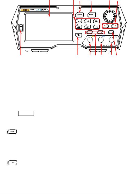
Figure 1-1 Front Panel
1.Power Key
Turns on or off the generator.
2.Align Key
Performs the phase alignment operation. For details, refer to descriptions in
"Align Phase".
3.CH1 Output Connector
BNC connector, with 50 Ω nominal output impedance.
When Output1 is enabled (the backlight turns on), this connector outputs waveforms according to the current configuration of CH1.
4. Channel Control Area
It is used to control the output of CH1.
— Press this key to enable the output of CH1, the backlight turns on. At this time, the [CH1] connector outputs the waveforms according to the current configuration of CH1.
—Press this key again to disable the output of CH1, and the backlight turns off.
It is used to control the output of CH2.
— Press this key to enable the output of CH2, the backlight turns on. At this time, the [CH2] connector outputs the waveforms according to the current configuration of CH2.
—Press this key again to disable the output of CH2, and the backlight turns off.
1-4 |
DG900 User's Guide |
Chapter 1 Quick Guide RIGOL
5. CH2 Output Connector
BNC connector, with 50 Ω nominal output impedance.
When Output2 is enabled (the backlight turns on), this connector outputs waveforms according to the current configuration of CH2.
6.Counter Measurement Signal Input Connector
BNC connector, with 1 MΩ input impedance. It is used to receive the signal measured by the counter.
CAUTION
To avoid damages to the instrument, the input signal voltage cannot exceed ±2.5 V.
7. Frequency Counter
Enables or disables the frequency counter.
—Press this key to enable the frequency counter, and the backlight turns on and blinks continuously.
—Press this key again to disable the frequency counter, and the backlight
turns off. At this time, the frequency counter is disabled.
Note: When the frequency counter is enabled, no waveforms will be output from the CH2 connector. When the frequency counter is disabled, waveforms are allowed to be output from the CH2 connector.
8.Arrow Key
—It is used to move the cursor to select the digit to be edited when you use the knob to set the parameters (pressing down the knob can enter the editing mode).
—In the user interface, it is used to move left or right the cursor.
9.Knob
—When you select a menu label in the interface, the knob can be used to move the cursor down (clockwise) or up (counterclockwise).
—It can be used to increase (clockwise) or decrease (counterclockwise) the value marked by the cursor when you use the knob to set the parameters (pressing down the knob can enter the editing mode). Press down the knob again to exit the editing mode.
—It can be used to select the desired waveform by moving the cursor with the knob when you select the waveform (pressing the right arrow key will locate the cursor to the right of the interface). Press down the knob to select the desired waveform.
—When you store or read a file, it can be used to select a storage location or select a file to be read. Press down the knob to unfold the currently selected directory.
—It can be used to select the desired parameter by moving the cursor with the knob when you set the common information (pressing the right arrow key will locate the cursor to the right of the interface). Press down the knob
DG900 User's Guide |
1-5 |
RIGOL |
Chapter 1 Quick Guide |
to select the desired parameter. Then, rotate the knob to modify the parameter, and press it down again to confirm your modification.
—It is used to select the desired configuration type in the Preset interface. Press down the knob to confirm your selection. At this time, a dialog box is displayed. Use the knob to select the corresponding button, then press down the knob to perform the corresponding operation (note that only when the button turns green, can your operation on the knob be valid).
10.Menu Key
Enters the waveform mode selection interface.
11.Home Key
Enters the main interface of the instrument.
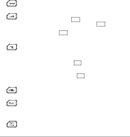
12.Function Keys
Restores the instrument to its preset state. At most 10 states can be preset.
Locks or unlocks the front-panel keys and the touch screen. In the unlocked state, press Lock to lock the front-panel keys and the touch screen. At this time, except the Lock key, all other keys on the front panel and the touch screen operation are invalid. Press the Lock key again to unlock the keys and the touch screen.
Used for manual trigger.
— The default trigger setting for the generator is Internal trigger. In this mode, when you select the sweep or burst mode, the generator outputs the waveforms continuously. At this time, press the Trig key, and instrument automatically switches to the manual trigger mode from auto trigger.
—Each time you press the Trig key, one sweep will be triggered manually or one burst will be output.
It is used to set the utility function parameters and system parameters.
Stores or recalls the instrument state or the user-defined arbitrary waveform data. A non-volatile memory (Disk C) is built in, and a USB storage device (Disk D) can be externally connected.
Gets the help information of any front-panel keys and the help information of the current interface.
1-6 |
DG900 User's Guide |
Chapter 1 Quick Guide |
RIGOL |
Note: When the instrument is in the remote mode, press this key to return to the local mode.
13.LCD
4.3-inch TFT (480×272) color LCD display. The menu label and parameter settings of the current function, system state, prompt messages, and other information can be clearly displayed on the LCD. For details, refer to descriptions in "User Interface".
DG900 User's Guide |
1-7 |
RIGOL |
Chapter 1 Quick Guide |
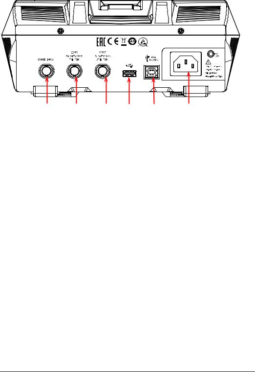
Rear Panel Overview
1 |
2 |
3 4 5
Figure 1-2 Rear Panel
6 |
1.[10MHz In/Out]
BNC female connector, with 50 Ω nominal impedance. Its function is determined by the clock type used by the instrument.
1)When internal clock source is selected, this connector (as 10MHz Out) outputs the 10 MHz clock signal generated by the internal crystal oscillator inside the generator.
2)When external clock source is selected, this connector (as 10MHz In) receives an external 10 MHz clock signal.
This connector is usually used to realize synchronization among multiple instruments. For details about the signals mentioned above, please refer to the descriptions in "Clock Source".
2.[CH1/Sync/Ext Mod/Trig/FSK]
BNC female connector, with 50 Ω nominal impedance. Its function is determined by the current working mode of CH1.
1)Sync
When the output of CH1 is enabled, this connector outputs the corresponding sync signal that matches the current configuration of CH1. For detailed information about the characteristics of the sync signals that correspond to various output signals, refer to the descriptions in "Sync Setting".
2)Ext Mod
When AM, FM, PM, or PWM of CH1 is enabled and external modulation source is selected, this connector receives an external modulation signal. Its input impedance is 1000 Ω. For details, refer to descriptions in
"Modulation".
1-8 |
DG900 User's Guide |
Chapter 1 Quick Guide |
RIGOL |
3)FSK
When ASK, FSK, or PSK of CH1 is enabled and external modulation source is selected, this connector receives an external modulation signal whose polarity can be set by users. Its input impedance is 1000 Ω. For details, refer to descriptions in "Modulation".
4)Trig In
When Sweep or Burst of CH1 is enabled and external trigger source is selected, this connector receives an external trigger signal whose polarity can be set by users.
5)Trig Out
When Burst of CH1 is enabled, and the internal/manual trigger source is selected, this connector outputs a trigger signal with specified edge type.
3.[CH2/Sync/Ext Mod/Trig/FSK]
BNC female connector, with 50 Ω nominal impedance. Its function is determined by the current working mode of CH2.
1)Sync
When the output of CH2 is enabled, this connector outputs the corresponding sync signal that matches the current configuration of CH2. For detailed information about the characteristics of the sync signals that correspond to various output signals, refer to the descriptions in "Sync Setting".
2)Ext Mod
When AM, FM, PM or PWM of CH2 is enabled and external modulation source is selected, this connector receives an external modulation signal. Its input impedance is 1000 Ω. For details, refer to descriptions in
"Modulation".
3)FSK
When ASK, FSK, or PSK of CH2 is enabled and external modulation source is selected, this connector receives an external modulation signal whose polarity can be set by users. Its input impedance is 1000 Ω. For details, refer to descriptions in "Modulation".
4)Trig In
When Sweep or Burst of CH2 is enabled and external trigger source is selected, this connector receives an external trigger signal whose polarity can be set by users.
5)Trig Out
When Burst of CH2 is enabled, and the internal/manual trigger source is selected, this connector outputs a trigger signal with specified edge type.
4.USB HOST
Supports FAT32 format Flash type USB storage device, RIGOL TMC digital oscilloscope (DS), and the USB-GPIB interface converter.
USB storage device: reads the waveform files or state files saved in the USB storage device; or stores the current instrument states or edited waveform data into the USB storage device. Besides, the contents displayed on the
DG900 User's Guide |
1-9 |

RIGOL |
Chapter 1 Quick Guide |
screen can also be saved to the USB storage device in the format of an image (*.Bmp).
TMC DS: seamlessly interconnects with the RIGOL DS that meets the TMC standard. Reads and stores the waveform data collected by the DS and rebuilds waveforms without distortion.
USB-GPIB interface converter (optional accessory): extends the GPIB interface for RIGOL instruments that integrates the USB HOST interface but not the GPIB interface.
5.USB DEVICE
It is used to connect the generator to a computer which can control the generator remotely by using PC software or by programming.
6.AC Power Cord Connector
The rated AC power source supported by the signal generator is (100-127 V,
45-440 Hz) or (100-240 V, 45-65 Hz), and its maximum input power shall not exceed 30 W. The specification of the fuse is 250 Vac, T4.0 A.
1-10 |
DG900 User's Guide |
Chapter 1 Quick Guide |
RIGOL |
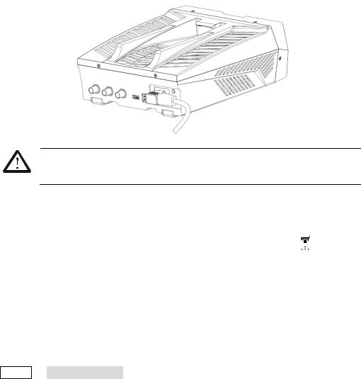
To Prepare for Use
To Connect to AC Power
Please use the power cord provided in the accessories to connect the signal generator to the AC power source, as shown in the figure below. The rated AC power source supported by the signal generator is (100-127 V, 45-440Hz) or (100-240 V, 45-65Hz), and its maximum input power shall not exceed 30 W. When the signal generator is connected to the AC power source via the power cord, the instrument automatically adjusts itself to within the proper voltage range, and you do not need to select the voltage range manually.
CAUTION
To avoid electric shock, ensure that the instrument is correctly grounded.
Turn-on Checkout
After connecting the instrument to the power source properly, press  on the front panel to start the signal generator. During the start-up, the instrument will undergo the initialization and self-check process. Then, it will enter a default interface. If you still fail to power on the instrument normally, refer to the methods in "Troubleshooting" to resolve the problem.
To Set the System Language
DG900 arbitrary waveform generator supports multiple languages. You can press Utility System Setting, and then select a desired language from the "Language" drop-down list.
DG900 User's Guide |
1-11 |
RIGOL |
Chapter 1 Quick Guide |
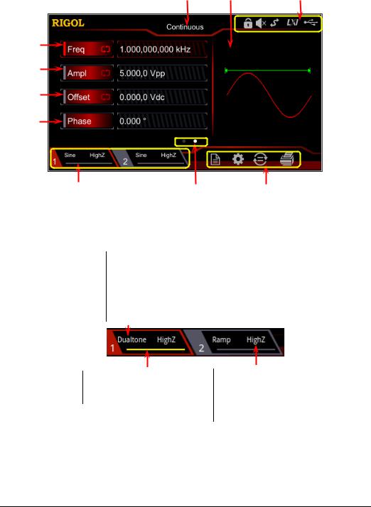
User Interface
The DG900 user interface is shown in the following figure.
6 |
5 |
4 |
7
8
9
10
1 |
2 |
3 |
Figure 1-1 User Interface
1.Channel Output Configuration Status Bar
Displays the current output configuration of the channel.
Selected Waveform: Sine/Square/Ramp/Pulse/Noise/Prbs/Dualtone/Harm /Rs232/DC/Arb/Sequence
Modulation Type: AM/FM/PM/ASK/FSK/PSK/PWM Sweep Type: Linear/Log/Step
Burst Type: Ncycle/Infinite/Gated
Channel Output State: ON: illuminated in yellow. OFF: grayed out.
Output Impedance Type:
High impedance: displays HighZ. Load: displays impedance (the default is 50 Ω and the range is from 1 Ω to 10 kΩ).
Note: Two channels can be enabled simultaneously, but you cannot select both channels at the same time.
1-12 |
DG900 User's Guide |

Chapter 1 Quick Guide |
RIGOL |
2.Interface Switchover
When left point is grayed out and the right point is illuminated, sliding right on the touch screen can switch to the waveform selection interface. When the left point is illuminated and the right point is grayed out, sliding left on the touch screen can switch to the current interface of waveform parameter setting.
3.Information Setting
 : opens the Store interface.
 : opens the Utility interface.
 : performs the channel copy function.
 : performs the screen print operation.
4.Status Bar
 : indicates that the front-panel keys and the screen are locked.
 : indicates that the beeper is disabled.
 : indicates that the instrument is in programming-controlled mode.
 : indicates that the instrument has been successfully connected to the local area network by using the network cable.
 : indicates that a USB storage device is found.
5.Waveform
Displays the currently selected waveform of each channel.
6.Interface Label
Displays the label of the current interface.
7.Frequency
Displays the frequency of the current waveform of each channel. Tap the Freq parameter input field to modify the parameter with the pop-up numeric keypad. You can also use the arrow keys and the knob to modify the parameter.
8.Amplitude
Displays the amplitude of the current waveform of each channel. Tap the Ampl parameter input field to modify the parameter with the pop-up numeric keypad. You can also use the arrow keys and the knob to modify the parameter.
9.Offset
Displays the DC offset of the current waveform of each channel. Tap the Offset parameter input field to modify the parameter with the pop-up numeric keypad. You can also use the arrow keys and the knob to modify the parameter.
10.Phase
Displays the phase of the current waveform of each channel. Tap the Phase
DG900 User's Guide |
1-13 |

RIGOL |
Chapter 1 Quick Guide |
parameter input field to modify the parameter with the pop-up numeric keypad. You can also use the arrow keys and the knob to modify the parameter.
1-14 |
DG900 User's Guide |
Chapter 1 Quick Guide |
RIGOL |
To Use the Built-in Help System
DG900 series provides the help information for each front-panel function menu and the current display interface. You can view the help information if you have any questions during the operation process.
1.Obtain the help information of the front panel keys
To get the help information about any front-panel key or menu softkey, press the Help/Local key first, and then press the desired key for the help information. Then, the corresponding help information is displayed.
2.Obtain the common help topics
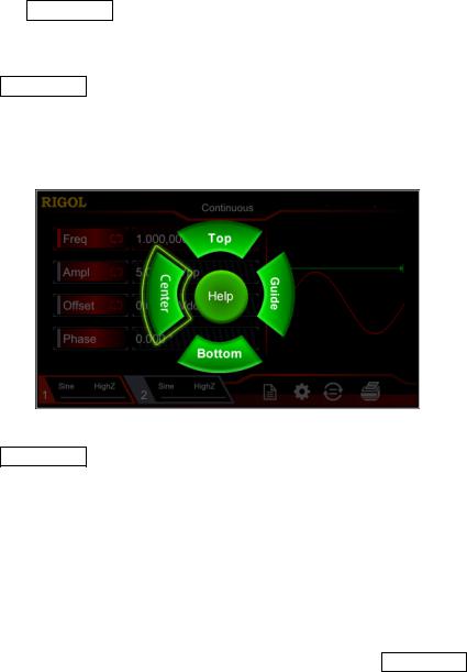
Press Help/Local on the front panel, and then the following interface is displayed below. Tap "Help" to enter the help interface. At this time, you can tap on the touch screen to move up and down the help items or rotate the knob to scroll up and down the list to select the desired help item. Then, the help information for the item is displayed in the interface.
3.Obtain the descriptions of the data in the interface
Press Help/Local on the front panel to enter the interface, as shown above. Tap "Center" to view the descriptions for the data in the center of the current interface. Tap "Top" to view the descriptions for the data in the top part of the current interface. Tap "Bottom" to view the descriptions for the data in the bottom part of the current interface. Tap "Guide" to enter the guide interface.
4.Page up/down operation
When the help information is displayed in multiple pages, you can tap to move up and down the touch screen to view the help information.
5.Close the current help information
When the help information is displayed in the interface, press Help/Local on the front panel to close the help information currently displayed on the screen.
DG900 User's Guide |
1-15 |
Loading...