


 Loading...
RIGOL
User’s Guide
DG1000Z Series Function/Arbitrary
Waveform Generator
Jul. 2015
RIGOL Technologies, Inc.

RIGOL
Guaranty and Declaration
Copyright
© 2013 RIGOL Technologies, Inc. All Rights Reserved.
Trademark Information
RIGOL is a registered trademark of RIGOL Technologies, Inc.
Publication Number
UGB09106-1110
Notices
RIGOL products are protected by patent law in and outside of P.R.C.
RIGOL reserves the right to modify or change parts of or all the specifications and pricing policies at company’s sole decision.
Information in this publication replaces all previously corresponding material.
RIGOL shall not be liable for losses caused by either incidental or consequential in connection with the furnishing, use or performance of this manual as well as any information contained.
Any part of this document is forbidden to be copied or photocopied or rearranged without prior written approval of RIGOL.
Product Certification
RIGOL guarantees this product conforms to the national and industrial standards in China as well as the ISO9001:2008 standard and the ISO14001:2004 standard. Other international standard conformance certification is in progress.
Contact Us
If you have any problem or requirement when using our products or this manual, please contact RIGOL.
E-mail: service@rigol.com Websites: www.rigol.com
DG1000Z User’s Guide |
I |

RIGOL
Safety Requirement
General Safety Summary
Please review the following safety precautions carefully before putting the instrument into operation so as to avoid any personal injury or damage to the instrument and any product connected to it. To prevent potential hazards, please use the instrument only specified by this manual.
Use Proper Power Cord.
Only the power cord designed for the instrument and authorized for use within the local country could be used.
Ground The Instrument.
The instrument is grounded through the Protective Earth lead of the power cord. To avoid electric shock, it is essential to connect the earth terminal of power cord to the Protective Earth terminal before any inputs or outputs.
Connect the Probe Correctly.
If a probe is used, do not connect the ground lead to high voltage since it has the isobaric electric potential as ground.
Observe All Terminal Ratings.
To avoid fire or shock hazard, observe all ratings and markers on the instrument and check your manual for more information about ratings before connecting.
Use Proper Overvoltage Protection.
Make sure that no overvoltage (such as that caused by a thunderstorm) can reach the product, or else the operator might expose to danger of electrical shock.
Do Not Operate Without Covers.
Do not operate the instrument with
covers or panels removed.
Do Not Insert Anything into the Holes of Fan.
Do not insert anything into the holes of the fan to avoid damaging the instrument.
Use Proper Fuse.
Please use the specified fuses.
Avoid Circuit or Wire Exposure.
Do not touch exposed junctions and components when the unit is powered.
Do Not Operate With Suspected Failures.
If you suspect damage occurs to the instrument, have it inspected by qualified service personnel before further operations. Any maintenance, adjustment or replacement especially to circuits or accessories must be performed by RIGOL authorized personnel.
Keep Well Ventilation.
Inadequate ventilation may cause increasing of temperature or damages to the device. So please keep well ventilated and inspect the intake and fan regularly.
Do Not Operate in Wet Conditions.
In order to avoid short circuiting to the
II |
DG1000Z User’s Guide |

RIGOL
interior of the device or electric shock, please do not operate in a humid environment.
Do Not Operate in an Explosive Atmosphere.
In order to avoid damages to the device or personal injuries, it is important to operate the device away from an explosive atmosphere.
Keep Product Surfaces Clean and Dry.
To avoid the influence of dust and/or moisture in air, please keep the surface of device clean and dry.
Electrostatic Prevention.
Operate in an electrostatic discharge protective area environment to avoid
damages induced by static discharges. Always ground both the internal and external conductors of the cable to release static before connecting.
Proper Use of Battery.
If a battery is supplied, it must not be exposed to high temperature or in contact with fire. Keep it out of the reach of children. Improper change of battery (note: lithium battery) may cause explosion. Use RIGOL specified battery only.
Handling Safety.
Please handle with care during transportation to avoid damages to buttons, knob interfaces and other parts on the panels.
DG1000Z User’s Guide |
III |
RIGOL
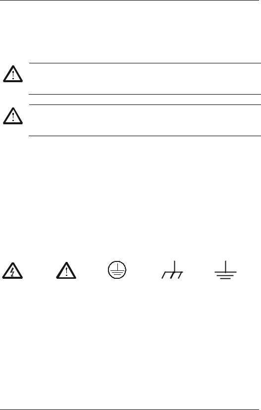
Safety Terms and Symbols
Terms Used in this Manual. These terms may appear in this manual:
WARNING
Warning statements indicate the conditions or practices that could result in injury or loss of life.
CAUTION
Caution statements indicate the conditions or practices that could result in damage to this product or other property.
Terms Used on the Product. These terms may appear on the Product:
DANGER indicates an injury or hazard may immediately happen. WARNING indicates an injury or hazard may be accessible potentially.
CAUTION indicates potential damage to the instrument or other property might occur.
Symbols Used on the Product. These symbols may appear on the product:
Hazardous |
Safety |
Protective |
Chassis |
Test |
Voltage |
Warning |
Earth |
Ground |
Ground |
|
Terminal |
|
|
|
|
|
|
|
IV |
DG1000Z User’s Guide |

RIGOL
Allgemeine Sicherheits Informationen
Überprüfen Sie diefolgenden Sicherheitshinweise sorgfältigumPersonenschädenoderSchäden am Gerätundan damit verbundenen weiteren Gerätenzu vermeiden.Zur Vermeidung vonGefahren, nutzen Sie bitte das Gerät nur so, wiein diesem Handbuchangegeben.
Um Feuer oder Verletzungen zu vermeiden, verwenden Sie ein ordnungsgemäßes Netzkabel
Verwenden Sie für dieses Gerät nur das für ihr Land zugelassene und genehmigte Netzkabel.
Erden des Gerätes
Das Gerät ist durch den Schutzleiter im Netzkabel geerdet. Um Gefahren durch elektrischen Schlag zu vermeiden, ist es unerlässlich, die Erdung durchzuführen. Erst dann dürfen weitere Einoder Ausgänge verbunden werden.
Anschluss einesTastkopfes
Die Erdungsklemmen der Sonden sindauf dem gleichen Spannungspegel des Instruments geerdet. SchließenSie die Erdungsklemmen an keine hohe Spannung an.
Beachten Sie alle Anschlüsse
Zur Vermeidung von Feuer oder Stromschlag, beachten Sie alle Bemerkungen und Markierungen auf dem Instrument. Befolgen Sie die Bedienungsanleitung für weitere Informationen, bevor Sie weitere Anschlüsse an das Instrument legen.
Verwenden Sie einen geeigneten Überspannungsschutz
Stellen Sie sicher, daß keinerlei Überspannung (wie z.B. durch Gewitter verursacht) das Gerät erreichen kann. Andernfallsbestehtfür den Anwender
die GefahreinesStromschlages.
Nicht ohne Abdeckung einschalten
Betreiben Sie das Gerät nicht mit entfernten Gehäuse-Abdeckungen.
Betreiben Sie das Gerät nicht geöffnet
Der Betrieb mit offenen oder entfernten Gehäuseteilen ist nicht zulässig. Nichts in entsprechende Öffnungen stecken (Lüfter z.B.)
Passende Sicherung verwenden
Setzen Sie nur die spezifikationsgemäßen Sicherungen ein.
Vermeiden Sie ungeschützte Verbindungen
Berühren Sie keine unisolierten Verbindungen oder Baugruppen, während das Gerät in Betrieb ist.
Betreiben Sie das Gerät nicht im Fehlerfall
Wenn Sie am Gerät einen Defekt vermuten, sorgen Sie dafür, bevor Sie das Gerät wieder betreiben, dass eine Untersuchung durch qualifiziertes Kundendienstpersonal durchgeführt wird.Jedwede Wartung, Einstellarbeiten oder Austausch von Teilen am Gerät, sowie am Zubehör dürfen nur von RIGOL autorisiertem Personal durchgeführt werden.
DG1000Z User’s Guide |
V |

RIGOL
Belüftung sicherstellen
Unzureichende Belüftung kann zu Temperaturanstiegen und somit zu thermischen Schäden am Gerät führen. Stellen Sie deswegen die Belüftung sicher und kontrollieren regelmäßig Lüfter und Belüftungsöffnungen.
Nicht in feuchter Umgebung betreiben
Zur Vermeidung von Kurzschluß im Geräteinneren und Stromschlag betreiben Sie das Gerät bitte niemals in feuchter Umgebung.
Nicht in explosiver Atmosphäre betreiben
Zur Vermeidung von Personenund Sachschäden ist es unumgänglich, das Gerät ausschließlich fernab jedweder explosiven Atmosphäre zu betreiben.
Geräteoberflächen sauber und trocken halten
Um den Einfluß von Staub und Feuchtigkeit aus der Luft auszuschließen, halten Sie bitte die Geräteoberflächen sauber und trocken.
Schutz gegen elektrostatische Entladung (ESD)
Sorgen Sie für eine elektrostatisch geschützte Umgebung, um somit Schäden und Funktionsstörungen durch ESD zu vermeiden. Erden Sie vor dem Anschluß immer Innenund Außenleiter der Verbindungsleitung, um statische Aufladung zu entladen.
Die richtige Verwendung desAkku.
Wenneine Batterieverwendet wird, vermeiden Sie hohe Temperaturen bzw. Feuer ausgesetzt werden.Bewahren Sie es außerhalbder Reichweitevon Kindern auf.UnsachgemäßeÄnderung derBatterie(Anmerkung:Lithium-Batteri e)kann zu einer Explosion führen. VerwendenSie nur von RIGOLangegebenenAkkus.
Sicherer Transport
Transportieren Sie das Gerät sorgfältig (Verpackung!), um Schäden an Bedienelementen, Anschlüssen und anderen Teilen zu vermeiden.
VI |
DG1000Z User’s Guide |

RIGOL
Sicherheits Begriffe und Symbole
Begriffe in diesem Guide. Diese Begriffe können in diesem Handbuch auftauchen:
WARNING
Die Kennzeichnung WARNING beschreibt Gefahrenquellen die leibliche Schäden oder den Tod von Personen zur Folge haben können.
CAUTION
Die Kennzeichnung Caution (Vorsicht) beschreibt Gefahrenquellen die Schäden am Gerät hervorrufen können.
Begriffe auf dem Produkt. Diese Bedingungen können auf dem Produkt erscheinen:
DANGER (dt. GEFAHR) weist auf eine Verletzung oder Gefährdung hin, die sofort geschehen kann.
WARNING (dt. WARNUNG) weist auf eine Verletzung oder Gefährdung hin, die möglicherweise nicht sofort geschehen.
CAUTION (dt. VORSICHT) bedeutet, dass eine mögliche Beschädigung des Instruments oder anderer Gegenstände auftreten kann.
Symbole auf dem Produkt. Diese Symbole können auf dem Produkt erscheinen:
GefährlicheS Sicherheits- Schutz-erde Gehäusemasse Erde pannung Hinweis
DG1000Z User’s Guide |
VII |
RIGOL
General Care and Cleaning
General Care:
Do not store or leave the instrument in where the instrument will be exposed to direct sunlight for long periods of time.
Cleaning:
Clean the instrument regularly according to its operating conditions. To clean the exterior surface, perform the following steps:
1.Disconnect the instrument from all power sources.
2.Clean the loose dust on the outside of the instrument with a lintfree cloth (with a mild detergent or water). When cleaning the LCD, take care to avoid scarifying it.
CAUTION
To avoid damages to the instrument, do not expose them to liquids which have causticity.
WARNING
To avoid injury resulting from short circuit, make sure the instrument is completely dry before reconnecting to a power source.
VIII |
DG1000Z User’s Guide |
RIGOL
Environmental Considerations
The following symbol indicates that this product complies with the requirements in WEEE Directive 2002/96/EC.
Product End-of-Life Handling
The equipment may contain substances that could be harmful to the environment or human health. In order to avoid release of such substances into the environment and harm to human health, we encourage you to recycle this product in an appropriate system that will ensure that most of the materials are reused or recycled appropriately. Please contact your local authorities for disposal or recycling information.
DG1000Z User’s Guide |
IX |

RIGOL
DG1000Z Series Overview
DG1000Z Series is a multifunctional generator that combines many functions in one, including Function Generator, Arbitrary Waveform Generator, Noise Generator, Pulse Generator, Harmonics Generator, Analog/Digital Modulator and Counter. As a multi-functional, high performance, high cost-effective and portable generator, it will be a new selection in education, R&D, production, test, etc.
Main Features:
Maximum output frequency (Sine): 30MHz and 60MHz
Innovative SiFi (Signal Fidelity): generate the arbitrary waveform point by point, undistortedly restore signal, precisely adjustable sample rate and low jitter (down to 200ps) for all waveforms including Square, Pulse and etc.
Arbitrary waveform memory for each channel: 8Mpts (standard), 16Mpts (optional)
Standard dual full functional channels which are equivalent to two independent generators
±1ppm frequency stability, -125dBc/Hz phase noise
Built-in 8 orders harmonics generator
Built-in 7 digits/s full function frequency counter with 200MHz bandwidth
Up to 160 built-in waveforms encompassing common signals in various fields including Engineering, Medical Electronics, Automotive Electronics, Mathematics and etc.
200MSa/s sample rate, 14bits vertical resolution
Standard powerful arbitrary waveform editing function. Users can also edit arbitrary waveform using PC software
Various modulation functions: AM, FM, PM, ASK, FSK, PSK and PWM
Standard waveform summing function. When it is enabled, you can superpose specified waveform onto basic waveform before output
Standard channel tracking function. When it is enabled, all parameters of dual channels can be modified synchronously according to user’s requirements
Standard interfaces: USB Host, USB Device, LAN (LXI Core Device 2011)
3.5 inches (320*240) color display
Portable design, only weight 3.5kg
X |
DG1000Z User’s Guide |

RIGOL
Document Overview
Subjects in this Manual
Chapter 1 Quick Start |
Briefly introduces the appearance and |
|
|
|
dimensions, front/rear panel and user interface |
|
|
of DG1000Z. |
Chapter 2 Front Panel Operations |
Introduce the main functions and operation |
|
|
|
methods of DG1000Z. |
Chapter 3 |
Remote Control |
Briefly introduce how to control the DG1000Z |
|
|
remotely. |
Chapter 4 |
Troubleshooting |
List the possible failures or problems and their |
|
|
solutions when using DG1000Z. |
Chapter 5 |
Specifications |
Provide the specifications of DG1000Z series. |
Chapter 6 Appendix |
Provide the information about the options and |
|
|
|
accessories list as well as warranty information |
|
|
of DG1000Z. |
Format Conventions in this Manual
1.Button:
The button at the front panel is denoted by the format of “Text Box + Button Name (Bold)” in the manual, for example, Sine.
2.Menu:
The menu is denoted by the format of “Character Shading + Menu Word (Bold)” in the manual, for example, Freq.
3.Connector:
The connector at the front or rear panel is denoted by the format of “Square Brackets+Connector Name (Bold)” in the manual, for example, [Counter].
4.Operation Steps:
The next step of the operation is denoted by an arrow “” in the manual. For example, Sine Freq represents pressing Sine at the front panel and then pressing Freq.
DG1000Z User’s Guide |
XI |

RIGOL
Content Conventions in this Manual
1. DG1000Z series function/arbitrary waveform generator includes DG1032Z and DG1062Z. In this manual, DG1062Z is taken as an example to introduce the operating method of the generator.
Model |
Channels |
Max. Frequency |
DG1062Z |
2 |
60MHz |
DG1032Z |
2 |
30MHz |
2. Both models of DG1000Z series function/arbitrary waveform generator are equipped with dual channels (CH1 and CH2). Unless otherwise specified, this manual takes CH1 as an example to introduce the operation methods which are also applied to CH2.
Manuals of this Product
The manuals of this product mainly include the quick guide, user’s guide, programming guide and data sheet. For the newest version of the desired manual, download it from the RIGOL website (www.rigol.com).
XII |
DG1000Z User’s Guide |
|
RIGOL |
Contents |
|
Guaranty and Declaration ......................................................................... |
I |
Safety Requirement ................................................................................ |
II |
General Safety Summary........................................................................... |
II |
Safety Terms and Symbols ....................................................................... |
IV |
Allgemeine Sicherheits Informationen......................................................... |
V |
Sicherheits Begriffe und Symbole ............................................................. |
VII |
General Care and Cleaning ..................................................................... |
VIII |
Environmental Considerations................................................................... |
IX |
DG1000Z Series Overview........................................................................ |
X |
Document Overview............................................................................... |
XI |
Chapter 1 Quick Start ......................................................................... |
1-1 |
General Inspection ................................................................................ |
1-2 |
To Adjust the Handle ............................................................................. |
1-3 |
Appearance and Dimensions................................................................... |
1-4 |
Front Panel Overview............................................................................. |
1-5 |
Rear Panel Overview............................................................................. |
1-11 |
Power On and Inspection ...................................................................... |
1-14 |
To Connect to Power ...................................................................... |
1-14 |
Power-on ...................................................................................... |
1-14 |
To Set the System Language........................................................... |
1-15 |
User Interface...................................................................................... |
1-16 |
Dual Channels Parameters Mode ..................................................... |
1-16 |
Dual Channels Graph Mode............................................................. |
1-19 |
Single Channel View Mode.............................................................. |
1-19 |
To Use the Built-in Help System ............................................................. |
1-20 |
Rack Mount Kit Installation (Option)....................................................... |
1-21 |
To Install Single Instrument ............................................................ |
1-21 |
To Install Dual Instruments............................................................. |
1-26 |
Chapter 2 Front Panel Operations ...................................................... |
2-1 |
To Output Basic Waveform ..................................................................... |
2-2 |
To Select Output Channel ................................................................ |
2-2 |
To Select Basic Waveform ................................................................ |
2-3 |
To Set Frequency/Period.................................................................. |
2-4 |
To Set Amplitude/High Level ............................................................ |
2-5 |
To Set Offset/Low Level................................................................... |
2-7 |
To Set Start Phase .......................................................................... |
2-8 |
Align Phase .................................................................................... |
2-9 |
To Set Duty Cycle (Square) ............................................................. |
2-10 |
To Set Symmetry (Ramp)................................................................ |
2-11 |
To Set Pulse Width/Duty Cycle (Pulse) ............................................. |
2-12 |
DG1000Z User’s Guide |
XIII |

RIGOL
To Set Leading/Trailing Edge Time (Pulse)........................................ |
2-13 |
To Enable Output........................................................................... |
2-14 |
Example: To Output Sine Waveform ................................................ |
2-15 |
To Output Arbitrary Waveform............................................................... |
2-17 |
To Enable Arbitrary Waveform......................................................... |
2-17 |
Output Mode and Sample Rate ....................................................... |
2-18 |
To Select Arbitrary Waveform.......................................................... |
2-19 |
To Edit Arbitrary Waveform............................................................. |
2-26 |
To Output Harmonic ............................................................................. |
2-30 |
Overview ...................................................................................... |
2-30 |
To Set Fundamental Waveform Parameters ...................................... |
2-31 |
To Set Harmonic Order................................................................... |
2-31 |
To Select Harmonic Type ................................................................ |
2-31 |
To Set Harmonic Amplitude............................................................. |
2-32 |
To Set Harmonic Phase .................................................................. |
2-32 |
Example: To Output Harmonic ........................................................ |
2-33 |
Modulation .......................................................................................... |
2-35 |
Amplitude Modulation (AM) ............................................................ |
2-35 |
Frequency Modulation (FM) ............................................................ |
2-39 |
Phase Modulation (PM) .................................................................. |
2-42 |
Amplitude Shift Keying (ASK).......................................................... |
2-45 |
Frequency Shift Keying (FSK).......................................................... |
2-48 |
Phase Shift Keying (PSK) ................................................................ |
2-51 |
Pulse Width Modulation (PWM) ....................................................... |
2-54 |
Sweep................................................................................................. |
2-57 |
To Enable Sweep Function.............................................................. |
2-57 |
Start Frequency and Stop Frequency ............................................... |
2-57 |
Center Frequency and Frequency Span ............................................ |
2-58 |
Sweep Type .................................................................................. |
2-59 |
Sweep Time.................................................................................. |
2-60 |
Return Time.................................................................................. |
2-60 |
Mark Frequency............................................................................. |
2-61 |
Start Hold ..................................................................................... |
2-61 |
Stop Hold ..................................................................................... |
2-62 |
Sweep Trigger Source .................................................................... |
2-62 |
Burst .................................................................................................. |
2-65 |
To Enable Burst Function................................................................ |
2-65 |
Burst Type .................................................................................... |
2-65 |
Burst Period .................................................................................. |
2-67 |
Gated Polarity ............................................................................... |
2-67 |
Burst Delay ................................................................................... |
2-68 |
Burst Trigger Source ...................................................................... |
2-68 |
Counter............................................................................................... |
2-70 |
To Enable the Counter.................................................................... |
2-70 |
To Set the Counter......................................................................... |
2-71 |
Store and Recall................................................................................... |
2-74 |
XIV |
DG1000Z User’s Guide |
|
|
RIGOL |
Storage System ............................................................................. |
2-74 |
|
File Type ....................................................................................... |
2-75 |
|
Browser Type ................................................................................ |
2-77 |
|
File Operation................................................................................ |
2-77 |
|
Seamless Interconnection with Oscilloscope ..................................... |
2-81 |
|
Utility and System Settings.................................................................... |
2-83 |
|
Channel Set................................................................................... |
2-84 |
|
Coupling Set.................................................................................. |
2-90 |
|
Channel Copy ................................................................................ |
2-93 |
|
Restore Default.............................................................................. |
2-94 |
|
To Set System Languege ................................................................ |
2-99 |
|
System Information........................................................................ |
2-99 |
|
System Set.................................................................................. |
2-100 |
|
I/O Configuration......................................................................... |
2-103 |
|
Print Set ..................................................................................... |
2-108 |
|
Test/Calibration............................................................................ |
2-108 |
|
To Use External Power Amplifier (Option)....................................... |
2-109 |
|
Chapter 3 |
Remote Control .................................................................. |
3-1 |
Remote Control via USB ......................................................................... |
3-2 |
|
Remote Control via LAN ......................................................................... |
3-5 |
|
Remote Control via GPIB (Option)........................................................... |
3-8 |
|
Chapter 4 |
Troubleshooting................................................................. |
4-1 |
Chapter 5 |
Specifications..................................................................... |
5-1 |
Chapter 6 |
Appendix............................................................................ |
6-1 |
Appendix A: Accessories and Options ...................................................... |
6-1 |
|
Appendix B: Specifications of Power Amplifier.......................................... |
6-2 |
|
Appendix C: Warranty............................................................................ |
6-4 |
|
Index ....................................................................................................... |
|
1 |
DG1000Z User’s Guide |
XV |
Chapter 1 Quick Start |
RIGOL |
Chapter 1 Quick Start
This chapter briefly introduces the appearance and dimensions, front/rear panel and user interface of DG1000Z as well as how to install the instrument into standard cabinet.
Subjects in this chapter:
General Inspection
To Adjust the Handle
Appearance and Dimensions
Front Panel Overview
Rear Panel Overview
Power On and Inspection
User Interface
To Use the Built-in Help System
Rack Mount Kit Installation (Option)
DG1000Z User’s Guide |
1-1 |

RIGOL |
Chapter 1 Quick Start |
General Inspection
1.Inspect the shipping container for damage.
Keep the damaged shipping container or cushioning material until the contents of the shipment have been checked for completeness and the instrument has passed both electrical and mechanical test.
The consigner or carrier shall be liable for the damage to instrument resulting from shipment. RIGOL would not be responsible for free maintenance/rework or replacement of the unit.
2.Inspect the instrument.
In case of any mechanical damage or defect, or if the instrument does not operate properly or pass the electrical and mechanical tests, contact your local sales representative of RIGOL.
3.Check the accessories.
Please check the accessories according to the packing lists. If the accessories are incomplete or damaged, please contact your RIGOL sales representative.
1-2 |
DG1000Z User’s Guide |
Chapter 1 Quick Start |
RIGOL |
To Adjust the Handle
To adjust the handle, please hold the handle by sides of the instrument and pull it outward, and then rotate the handle to the desired position (as shown in the figure below).
Adjusting the Handle
Viewing Positions |
Move Position |
DG1000Z User’s Guide |
1-3 |

RIGOL |
Chapter 1 Quick Start |
Appearance and Dimensions
Front View |
Unit: mm |
Side View |
Unit: mm |
1-4 |
DG1000Z User’s Guide |

Chapter 1 Quick Start |
RIGOL |
Front Panel Overview
The front panel of DG1000Z is shown below. Click the numbers in the figure to view the corresponding description.
16 |
15 |
14 |
13 |
12 |
11 |
10 |
1 |
2 |
3 |
4 |
5 |
6 |
7 |
8 |
9 |
Figure 1-1 Front Panel
1.Power Key
The power key is used to turn the generator on or off.
2.USB Host
Support USB storage device, RIGOL TMC digital oscilloscope (DS), power amplifier (PA) and USB to GPIB interface converter (Option).
USB storage device: read the waveform or state files saved in the USB storage device or store the current instrument states or edited waveform data into the USB storage device. In additional, the content displayed on the screen also can be saved as a picture file (*.Bmp) into the USB storage device.
TMC DS: seamlessly interconnect with the RIGOL DS that meets the TMC standard. Read and store the waveform data collected by the DS and rebuilt waveform losslessly.
PA (option): support the RIGOL power amplifier (such as PA1011). You can configure it online and the signal is outputted after whose power is amplified.
USB to GPIB interface converter (Option): expand the GPIB interface for RIGOL instrument with USB Host interface but without GPIB interface.
DG1000Z User’s Guide |
1-5 |
RIGOL |
Chapter 1 Quick Start |
3.Page Up/Down
Open the next page of the current function menu or return to the first page.
4.Return to the Previous Menu
Exit the current menu and return to the previous menu.
5.CH1 Output Connector
BNC connector with 50Ω nominal output impedance.
When Output1 is enabled (the backlight turns on), this connector outputs waveform according to the current configuration of CH1.
6.CH2 Output Connector
BNC connector with 50Ω nominal output impedance.
When Output2 is enabled (the backlight turns on), this connector outputs waveform according to the current configuration of CH2.
7.Channels Control Area
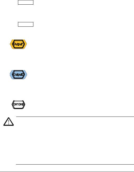
It is used to control the output of CH1.
— Press this key to open the output of CH1, the backlight turns on and the [CH1] connector outputs the waveform according to the current configuration of CH1.
—Press this key again to close the output of CH1 and the backlight turns off.
It is used to control the output of CH2.
— Press this key to open the output of CH2, the backlight turns on and the [CH2] connector outputs the waveform according to the current configuration of CH2.
—Press this key again to close the output of CH2 and the backlight turns off.
It is used to switch the current selected channel between CH1 and CH2.
CAUTION
Overvoltage protection of the output channels of CH1 and CH2 will take effect once any of the following conditions is met. When the overvoltage protection takes effect, the prompt message will be displayed on the screen and the output will be disabled.
The amplitude setting in the generator is greater than 2Vpp or the
output offset is greater than |2VDC|, the input voltage is greater than ±11.5×(1±5%)V (<10kHz).
The amplitude setting in the generator is lower than or equal to
2Vpp or the output offset is lower than or equal to |2VDC|, the input voltage is greater than ±3.5×(1±5%)V (<10kHz).
1-6 |
DG1000Z User’s Guide |

Chapter 1 Quick Start |
RIGOL |
8.Input Connector for the Signal Measured by Counter
BNC connector with 1MΩ input impedance. It is used to accept the signal measured by the counter.
CAUTION
To avoid damages to the instrument, the input signal voltage can not exceed ±7Vac+dc.
9.Counter
It is used to turn the counter on or off.
—Press this key to turn the counter on, the backlight turns on and the indicator at the left of Counter blinks.
—Press this key again to turn the counter off and the backlight turns off.
Note: the sync signal of CH2 will be disabled if the counter is turned on and it will be enabled after the counter is turned off.
10.Direction Keys
—Used to move the cursor to select the digit to be edited when setting parameter using knob.
—Used to delete the number at the left of the cursor when inputting parameter using numeric keyboard.
—Used to unfold or fold the current selected directory when storing or reading file.
—Used to move the cursor to select the specified character in filename input area when editing filename.
11.Knob
—Used to increase (clockwise) or decrease (counterclockwise) the value marked by the cursor when setting parameter using knob.
—Used to select the storage location when storing a file or used to select the file to be read when reading file.
—Used to select a character from the virtual keyboard when editing filename.
—Used to select a desired built-in arbitrary waveform from Arb Select Wform BuiltIn.
12.Numeric Keyboard
It consists of numbers (0 to 9), decimal point (.), sign key (+/-) and is used to set parameters.
Note:
1)The sign key is used to switch between uppercase and lowercase when editing filename.
2)Use the decimal point key to quickly save the content displayed in the user interface in the USB storage device in *.Bmp format (for the detailed steps, please refer to “Print Set”).
DG1000Z User’s Guide |
1-7 |
RIGOL |
Chapter 1 Quick Start |
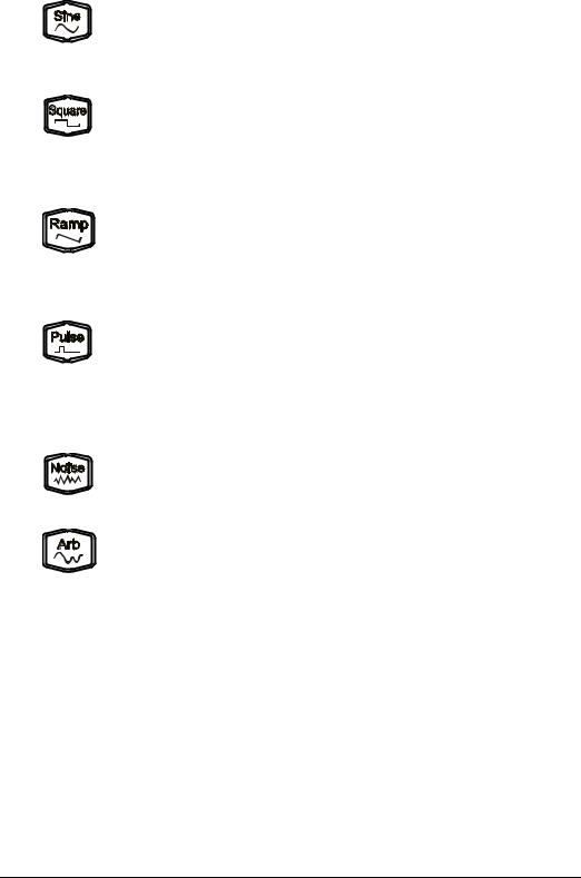
13. Waveforms Key
Output Sine with frequency from 1μHz to 60MHz.
— The backlight turns on when this function is selected.
— You can set Freq/Period, Ampl/HiLevel, Offset/LoLevel and Start Phase of sine waveform.
Output Square with frequency from 1μHz to 25MHz and variable duty cycle.
— The backlight turns on when this function is selected.
—You can set Freq/Period, Ampl/HiLevel, Offset/LoLevel, Duty Cycle and Start Phase of square waveform.
Output Ramp with frequency from 1μHz to 1MHz and variable symmetry.
— The backlight turns on when this function is selected.
—You can set Freq/Period, Ampl/HiLevel, Offset/LoLevel, Symmetry and Start Phase of ramp waveform.
Output Pulse with frequency from 1μHz to 25MHz and variable pulse width and edge time.
— The backlight turns on when this function is selected.
—You can set Freq/Period, Ampl/HiLevel, Offset/LoLevel, Width/Duty, Leading, Trailing and Start Phase of pulse waveform.
Output Gauss Noise with 60MHz bandwidth.
— The backlight turns on when this function is selected.
— You can set Ampl/HiLevel and Offset/LoLevel of Noise.
Output Arbitrary waveform with frequency from 1μHz to 20MHz.
— Support Sample Rate and Frequency output modes.
— Up to 160 built-in waveforms and support powerful arbitrary waveform editing function.
—The backlight turns on when this function is selected.
—You can set Freq/Period, Ampl/HiLevel, Offset/LoLevel and Start Phase of arbitrary waveform.
1-8 |
DG1000Z User’s Guide |

Chapter 1 Quick Start |
RIGOL |
14. Function keys
Output multiple types of modulated waveforms.
— Support multiple modulation types: AM, FM, PM, ASK, FSK, PSK and PWM.
—Support internal and external modulation sources.
—The backlight turns on when this function is selected.
Output sweep waveform for Sine, Square, Ramp and Arb
(except DC).
—3 sweep types: Linear, Log and Step.
—3 types of trigger sources: Internal, External and Manual.
—Provide frequency mark function used to control the status of the sync signal.
—The backlight turns on when this function is selected.
Output Burst waveform for Sine, Square, Ramp, Pulse and Arb
(except DC).
—3 burst types: NCycle, Infinite and Gated.
—Noise can also be used to generate Gated Burst.
—3 types of trigger sources: Internal, External and Manual.
—The backlight turns on when this function is selected.
Used to set the auxiliary function parameters and system parameters. The backlight turns on when this function is selected.
Store or recall the instrument state or the user-defined arbitrary waveform data.
—A nonvolatile memory (C disk) is built in and a USB storage device (D disk) can be connected.
—The backlight turns on when this function is selected.
To get the help information of any front panel key or menu softkey, press this key and then press the desired key.
Note:
1)When the instrument is working in remote mode, press this key to return to local mode.
2)Used to lock or unlock the keyboard. Press and hold Help to lock the front panel keys and at this point, the front panel keys (except Help) are not available. Press and hold this key again to unlock.
DG1000Z User’s Guide |
1-9 |

RIGOL |
Chapter 1 Quick Start |
15.Menu Softkeys
Correspond to the left displayed menus respectively. Press this softkey to activate the corresponding menu.
16.LCD
3.5 inches TFT (320×240) color LCD display. The current function menu, settings, system state as well as prompt messages and etc. can be clearly displayed (for the detailed information, refer to “User Interface”).
1-10 |
DG1000Z User’s Guide |

Chapter 1 Quick Start |
RIGOL |
Rear Panel Overview
The rear panel of DG1000Z is as shown in the figure below. Click the numbers in the figure to view the corresponding description.
1 |
2 |
3 |
4 |
5 |
6 |
Figure 1-2 Rear Panel
1.[CH1/Sync/Ext Mod/Trig/FSK]
BNC female connector with 50Ω nominal impedance.
Its function is determined by the current work mode of CH1.
1) Sync
When the output of CH1 is enabled, this connector outputs the corresponding sync signal. For detailed information about the characteristics of the sync signals corresponding to various output signals, refer to the introduction in “Sync Set”.
2)Ext Mod
When AM, FM, PM or PWM of CH1 is enabled and external modulation source is selected, this connector accepts an external modulation signal and the input impedance is 1000Ω. For the detailed introduction, refer to “Modulation”.
3)FSK
When ASK, FSK or PSK of CH1 is enabled and external modulation source is selected, this connector accepts an external modulation signal whose polarity can be set by users and the input impedance is 1000Ω. For the detailed introduction, refer to “Modulation”.
DG1000Z User’s Guide |
1-11 |

RIGOL |
Chapter 1 Quick Start |
4)Trig In
When Sweep or Burst of CH1 is enabled and external trigger source is selected, this connector accepts an external trigger signal whose polarity can be set by users.
5)Trig Out
When Sweep or Burst of CH1 is enabled and internal or manual trigger source is selected, this connector outputs a trigger signal with specified edge type.
2.[CH2/Sync/Ext Mod/Trig/FSK]
BNC female connector with 50Ω nominal impedance.
Its function is determined by the current work mode of CH2.
1) Sync
When the output of CH2 is enabled, this connector outputs the corresponding sync signal. For detailed information about the characteristics of the sync signals corresponding to various output signals, refer to the introduction in “Sync Set”.
2)Ext Mod
When AM, FM, PM or PWM of CH2 is enabled and external modulation source is selected, this connector accepts an external modulation signal and the input impedance is 1000Ω. For the detailed introduction, refer to “Modulation”.
3)FSK
When ASK, FSK or PSK of CH2 is enabled and external modulation source is selected, this connector accepts an external modulation signal whose polarity can be set by users and the input impedance is 1000Ω. For the detailed introduction, refer to “Modulation”.
4)Trig In
When Sweep or Burst of CH2 is enabled and external trigger source is selected, this connector accepts an external trigger signal whose polarity can be set by users.
5)Trig Out
When Sweep or Burst of CH2 is enabled and internal or manual trigger source is selected, this connector outputs a trigger signal with specified edge type.
1-12 |
DG1000Z User’s Guide |
Loading...