


GS10
Manuel d’entretien
Installation, use and maintenance instructions
Instrucciones para la instalación, uso y mantenimiento
Montage und Bedienungsanleitung
2902721 (0)
Gas-Gebläsebrenner
Brûleur gaz à air soufflé
Forced draught gas burner
Quemador de gas de aire soplado
CODE - CÓDIGO
MODELL - MODELE - MODEL - MODELO TYP - TYPE - TIPO
3755426
GS10 554T1
D
F
GB
E
Einstufiger Betrieb
Fonctionnement à 1 allure
One stage operation
Funcionamiento de una llama

2721
1
GB
INDEX
1. BURNER DESCRIPTION
Gas burner with one stage working.
1.1 BURNER EQUIPMENT
Insulating gasket . . . . . . . . . . . . . No. 1 Screws and nuts for flange to be fixed to boiler . . . No. 4
Cable grommet . . . . . . . . . . . . . . No. 1 Screw for fixing the cover . . . . . . . . . . . . . . . . . . . No. 1
Hinge . . . . . . . . . . . . . . . . . . . . . . No. 1 7 pin plug . . . . . . . . . . . . . . . . . . . . . . . . . . . . . . . No. 1
1. BURNER DESCRIPTION . . . . . . . . . . . 1
1.1 Burner equipment . . . . . . . . . . . . . . . . . 1
2. TECHNICAL DATA . . . . . . . . . . . . . . . . 2
2.1 Technical data . . . . . . . . . . . . . . . . . . . . 2
2.2 Overall dimensions . . . . . . . . . . . . . . . . 2
2.3 Working field . . . . . . . . . . . . . . . . . . . . . 2
3. INSTALLATION. . . . . . . . . . . . . . . . . . . 3
3.1 Boiler fixing . . . . . . . . . . . . . . . . . . . . . . 3
3.2 Probe-electrode positioning . . . . . . . . . . 4
3.3 Gas feeding line . . . . . . . . . . . . . . . . . . 4
3.4 Electrical wiring . . . . . . . . . . . . . . . . . . . 5
3.4.1 Standard electrical wiring . . . . . . . . . . . 5
3.4.2 Electrical wiring with gas leak control
device . . . . . . . . . . . . . . . . . . . . . . . . . . 6
4. WORKING . . . . . . . . . . . . . . . . . . . . . . . 6
4.1 Combustion adjustment . . . . . . . . . . . . . . 6
4.2 Combustion head setting. . . . . . . . . . . . . 6
4.3 Air damper setting . . . . . . . . . . . . . . . . . . 7
4.4 Combustion check. . . . . . . . . . . . . . . . . . 7
4.5 Air pressure switch . . . . . . . . . . . . . . . . . 7
4.6 Burner start-up cycle . . . . . . . . . . . . . . . . 8
4.7 Start-up cycle diagnostics . . . . . . . . . . . . 8
4.8 Operating fault diagnostics . . . . . . . . . . . 9
5. MAINTENANCE . . . . . . . . . . . . . . . . . . . 9
6. FAULTS / SOLUTIONS . . . . . . . . . . . . . . 10
1 – Air damper actuator
2 – Air dampers
3 – 7 pole socket for electrical supply
and control
4 – 6 pole socket for gas train
5 – Cable grommet
6 – Screw for fixing the cover
7 – Air pressure switch
8 – Control box
9 – Reset button with lock-out lamp
■
The burner meets protection level of IP 40, EN 60529.
■
CE marking according to Gas Appliance directive 90/396/EEC; PIN 0063AP6680.
According to directives: EMC 89/336/EEC, Low Voltage 73/23/EEC, Machines 98/37/EEC and
Efficiency 92/42/EEC.
■
Gas train according to EN 676.
NOTE
The cable grommet (5) and the screw for fixing the cover (6) supplied with the
burner, must be fitted to the same side of the gas train.
Fig. 1
D4181
6
5 3
2
19
8
7
4
2721
2
GB
2. TECHNICAL DATA
2.1 TECHNICAL DATA
For gas family 3 (LPG) ask for separate kit.
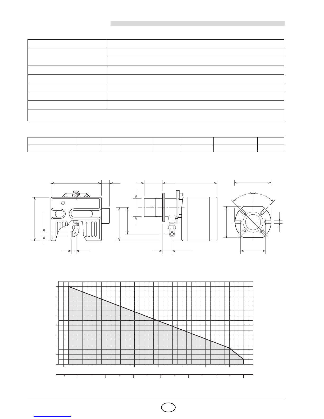
2.2 OVERALL DIMENSIONS
2.3 WORKING FIELD
(as EN 676)
Thermal power (1) 42 – 116 kW - 36,000 – 100,000 kcal/h
Natural gas
(Family 2)
Net heat value: 8 – 12 kWh/Nm
3
- 7,000 – 10,340 kcal/Nm
3
Pressure: min. 16 mbar - max. 100 mbar
Electrical supply Single phase, 230 V
±
10% ~50Hz
Motor 230V / 0.7A
Capacitor 2
µF
Ignition transformer
Primary 230V / 1.8 A - Secondary 8 kV / 30 mA
Absorbed electrical power 0.13 kW
(1) Reference conditions:
Temp. 20°C - Barometric pressure 1013 mbar – Altitude 0 m above sea level.
COUNTRY FR DK - AT - GR - SE - IT LU DE GB - IE - ES - PT NL
GAS CATEGORY II2Er3P II2H3B/P II2E3B/P II2ELL3B/P II2H3P II2L3B/P
■
Combustion head extension, supplied separately.
FlangeBurner
305 110 346 185
33 61
45°
36
ø 105
262
160
Rp 3/4
204
142
■
170
D4201
130
11
45°
Thermal power
D5256
0.8
0
0.2
0.4
0.6
40,000 50,000 60,000 70,000
kcal/h
1206050 70 80 kW
1.0
110
80,000
1.2
90 100
90,000
1.4
40
1.6
100,000
Pressure in the combustion
chamber – mbar
2721
3
GB
TEST BOILER
The working field has been defined according to EN 676 standard.
COMMERCIAL BOILERS
The burner-boiler matching is assured if the boiler conforms to EN 303 and the combustion chamber dimensions are similar to those shown in the diagram EN 676. For applications where the boiler does not conform to
EN 303, or where the combustion chamber is much smaller than the dimensions given in EN 676, please consult the manufacturers.
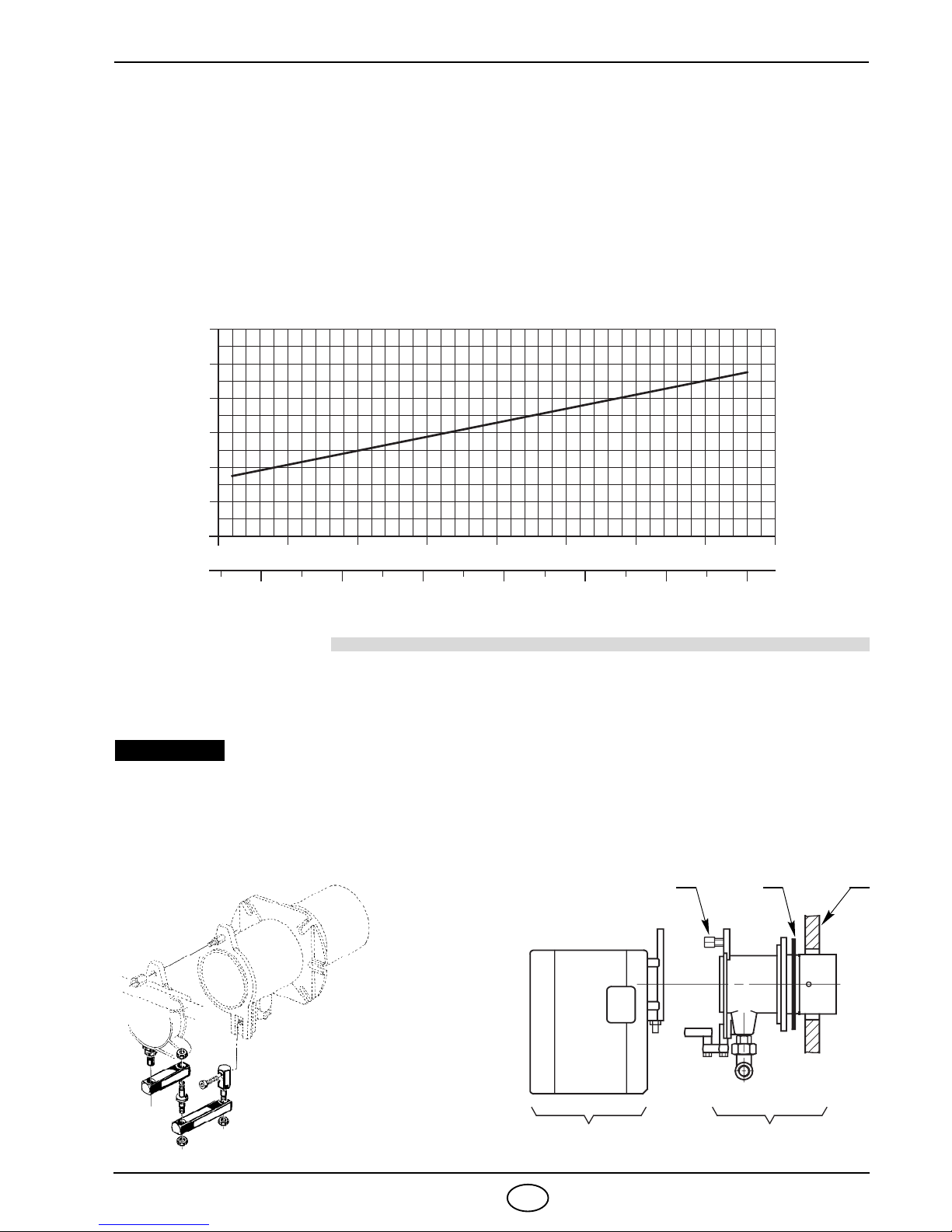
CORRELATION BETWEEN GAS PRESSURE AND BURNER OUTPUT
To obtain the maximum output, a gas head pressure of 5.8 mbar is measured (M2, see chapter 3.3, page 4) with
the combustion chamber at 0 mbar using gas G20 with a net heat value of 10 kWh/Nm
3
(8,570 kcal/Nm3).
3. INSTALLATION
THE BURNER MUST BE INSTALLED IN CONFORMITY WITH LEGISLATION AND LOCAL STANDARDS.
3.1 BOILER FIXING
4
1
2
3
5
6
7
Gas pressure in the
combustion head – mbar
40,000 50,000 60,000 70,000 kcal/h
1206050 70 80 kW
Thermal power
D5257
110
80,000
90 100
90,000
40
100,000
S7392
1 3 2
A B
D6323
HINGE
ASSEMBLY
Boiler door must have a max. thickness of 90 mm,
refractory lining included.
If thickness is greater (max. 150 mm), a combustion
head extension must be fitted, which is supplied
separately.
IMPORTANT
■
Separate the combustion-head assembly
from the burner body by removing nut (1) and
removing group (A).
■
Fix the head assembly group (B) to the boiler
(2) inser t the supplied insulating gasket (3).
 Loading...