

RIDGID TS3612 Owner's Manual

76
2:1(560$18$/
)RU<RXU6DIHW\
5HDGDOOLQVWUXFWLRQVFDUHIXOO\
6DYHWKLVPDQXDOIRUIXWXUH
UHIHUHQHFH
,1&+&2175$&725
6(5,(6%(/7'5,9(6$:
Part No. SP6461 Printed in U.S.A.

Table of Contents
Section Page
Table of Contents ..........................................2
Safety Instructions For Table Saw ................3
Safety Signal Words ..................................3
Before Usi ng The Saw ............................... 3
When Installing Or Moving The Saw ............ 4
Before Each Use ........................................... 4
To Reduce the Risk of Injury From Jams, Slips Or
Thrown Pieces (Kickbacks Or Throwbacks) ..5
Plan Ahead To Protect Your Eyes, Hands,
Face and Ears ............................................ 6
Whenever Sawblade Is Spinning ................. 7
Additional Safety Instructions For: Ripping ... 8
Additional Safety Instructions For: Crosscut . 9
Additional Safety Instructions For
Herc-U-Lift™ Caster System: ................... 9
Glossary of Terms for Woodworking ............. 9
Motor Specifications and Electrical
Requirements ......................................... 11
Power S upply an d Motor Specifications ..11
General Electrical Connections ...............11
Changing Motor Voltage ..........................13
Motor Thermal Overload Protector .......... 14
Wire Sizes ................................................ 14
Unpacking and Checking Contents .............15
Tools Needed ........................................... 15
Unpac king ..... ........... ........ ........... ............ .. 1 5
List of Loose Parts .................................... 16
Herc-U-Lift™ Caster Carton .....................17
Loose Parts ............................................... 17
Assemb ly ..... ........... ............ ........... ........ ......17
Installing Handwheels ...............................17
Assemb lin g Le g Sta nd ..............................1 8
Mountin g You r Saw ......... ......................... 19
Assemb lin g Ta ble Extens i on s . .... .... .... ......20
Checking Table Insert ...............................21
Checking Heeling Adjustment or Parallelism
of Sawblade to Miter Gauge Groove ......22
Checki ng Blade Tilt, or Squareness of Blade
to Table ..................................................24
Checking Tilt Mechanism ..........................25
Assembling Herc-U-Lift™ Caster System . 26
Assembly Tips .......................................... 26
Upper Assembly ....................................... 26
Lower Assembly ....................................... 27
Assembling Herc-U-Lift™ Caster System to
Saw ........................................................28
Installation Instructions ............................. 28
Operation of Herc-U-Lift™ Caster System 29
Installing Front Rip Fence Guide Bar ........30
Installing Rear Fence Guide Bar ............... 31
Adjus tin g Rip Fence G uide Bars . .............. 32
Installing Spacer Bar .................................33
Rip Fence Alignment Adjustment .............34
Rip Fence Lock Lever Adjustment ............34
Adjus tin g Fenc e Ind icat or ....... ..................35
Installing Blade Guard .............................. 35
Aligning Blade Guard ................................36
ection Page
S
Mounting the Motor ...................................37
Installing Belt ............................................38
Installing Belt Guard ................................. 38
Mounting Switch and End Caps ................ 39
Securing Electrical Cords .........................40
Installing Guide Bar End Caps ..................40
Getting to Know Your Table Saw ................ 41
Additional Safety Instructions When Using Zero
Clearanc e Inse rt ... ... .... ............................43
Remove the Existing Metal Insert..............43
Installing Zero Clearance Insert/S awblade 43
Installing Zero Clearance Insert/Dado Blades44
Operation Tips ..........................................45
Safety Instructions for Basic Saw Operations 48
Before Each Use .........................................48
To Reduce the Risk of Injury From Jams, Slips Or
Throw n Pi eces (Kic kba cks Or Thro w backs ) 48
Plan Ahead To Protect Your Eyes, Hands,
Face and Ears ..........................................49
Whenever Sawblade Is Spinning ............. 50
Work Feed Devic e s ............. ........................ 51
Attaching Wood Face Board .....................51
Push Block . .... .... .... ................................... 52
Auxiliary Fe nce .. .... ... .... ............................53
Fence Extension........................................54
Basic Saw Operations ................................. 55
Using the Miter Gauge ..............................55
Additional Safety Instructions for Crosscutting 55
Crosscu tting ....... ........... ........ ........... ......... 55
Repetitive Crosscutting .............................56
Miter Crosscutting .....................................57
Bevel Crosscutting ....................................57
Compoun d Cros scu tti ng ........................... 57
Using the Rip Fence .................................58
Additional Safety Instructions for Rip Cuts 58
Ripping ... ........ ........ ....... .... ........ ....... ........ . 59
Bevel Ripping Narrow Work ......................60
Using Featherboards for Thru-Sawing ......61
Using Featherboards for
Non Thru-Sawing ....................................61
Resawing .................................................. 62
Using Carbide Tipped Blades ...................63
Dadoing ....................................................63
Rabbeting .................................................64
Ploughing and Molding .............................64
Molding ..................................................... 65
Adjustmen ts .. .... .... .... ................................... 66
Miter Gauge .............................................. 66
Maintaining Your Table Saw ....................... 67
Maintenance ............................................. 67
Lubrication ................................................ 68
RIDGID Recommends the Following
Accessories ............................................ 68
Troublesh ootin g ........ ....... ........ ....... .... ........ .69
General .. ................................................... 69
Motor .. .... .... ............................................... 70
Repair Parts ................................................72
2

Safety Instructions For Table Saw
Safety is a combination of common sense, staying alert and know ing how
your table saw works. Read this manual to understand this table saw.
Safety Signal Words
DANGER: means if the safety infor-
mation is not followed someone will
be seriously injured or killed.
WARNING: means if the safety information is not followed someone
Before Using The Saw
WARNING: Some dust created by
power sa ndin g, s awi ng, gri ndi ng,
drilling, and other construction
activities contains chemica ls
known (to the State of California)
to cause cancer, birth defects or
other rep r od uc ti v e harm. Some
examples of these chemicals are:
Lead from lead-bases pain ts
• Crystalline silica from bricks
and cement and other mason ry
produc ts , and
• Arsenic and chromium from
chemically-treate d lumber.
Y o ur risk from these exposures
varies , depending on how often
you do th is type of work. To
reduce your exposure to these
chemicals: work in a well ventilated area, and work with
approved safety equipment,
such as those dust masks that
are specially designed to filter
out microscopic particles.
could be seriously injured or killed.
CAUTION: means i f th e safety infor-
mation is not followed someone may
be injured.
WARNING: To reduce the risk of
mistakes that could cause serious, per ma nent injury, do not
plug the tabl e saw in unti l the fo llowing steps have been satisfactorily completed.
• Completely assemble and align saw
(See “Assembly” section).
• Learn the use and function of the
ON-OFF switch, blade guard,
spreader, anti-kickback device,
miter gauge, rip fence, table insert,
blade elevation and blade tilt controls (See “Getti ng to Know Your
Table Saw” section).
• Review and underst and all safety
instructions and operating procedures in this manual.
• Review the maintenance methods
for this saw ( See “Maintaining Your
Table Saw” section)).
3
Safety Instructions For Table Saw (continued)
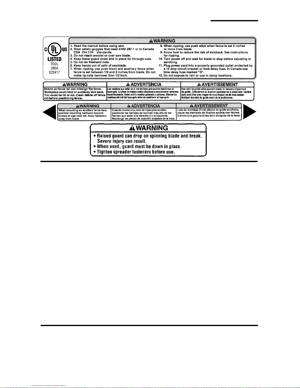
• Find and read all the warning labels found on the saw (shown below).
When Installing Or Moving The Saw
Reduce the Risk of Dangerous
Environment.
• Use the saw in a dry, indoor place
protected from rain.
• Keep work area well lighted.
• Use recommended accessori es.
Consult the owner’s manual for recommended accessories. The use of
improper accessories may cause
risk of injury to persons.
To reduce the risk of injury from
unexpected saw movement.
• Bolt or clamp the saw to firm level
surface where there is plenty of
room to handle and properly support
the workpiece (See “Assembly-
Mounting Your Saw” section).
• Support the saw so the table is level
and the saw does not rock.
• When using a table extension longer
• Put the saw where neither operator
• To reduce the risk of injury from
• Never St and On Tool. Serious
than 12" attached to any side of the
saw, bolt the saw to a stationary surface or prop up the outer end of the
extension from the floor or bench
top to keep the saw from tipping.
nor bystanders must stand in line
with the sawblade.
electrical shock, make sure your fingers do not touch the plug’s metal
prongs when plugging in or unplugging the saw.
injury could occur if the tool tips or
you accidentally hit the cutting tool.
Do not store anything above or near
the tool where anyone might stand
on the tool to reach them.
Before Each Use
Inspect your saw.
• To reduce the risk of injury from
accidental starting, turn the switch
off, unplug the saw, and remove the
switch key before raising or removing the guard, changing the cutting
tool, changing the setup, or adjusting anything. Make sure switch is in
4

OFF position before plugging in.
• Check for alignment of moving
parts, binding of moving parts,
breakage of parts, saw stability, and
any other conditions that may affect
the way the saw works.
• If any part is missing, bent or broken
in any way, or any electrical part
does not work properly , turn the saw
off and unplug the saw.
• Replace damaged or missing parts
before using the saw again.
• Use the sawblade guard, spreader
and anti-kickback pawls for any
comes through the top of the workpiece). Make sure the anti-kickback
pawls work properly. Make sure the
spreader is in line with sawblade
(See “Assembly-Aligning Blade
Guard” section).
• Rem ove adjusting keys and
wrenches. Form a habit of checking
for and removing keys and adjusting
wrenches from table top before turning saw on.
• Make sure all clamps and locks are
tight and no parts have excessive
play.
thru-sawing (whenever the blade
To Reduce the Risk of Injury From Jams, Slips Or Thrown Pieces
(Kickbacks Or Throwbacks)
Inspect Your Blade.
• Choose the right blade or cutting
accessory for the material and the
type of cutting you plan to do.
• Use The Right Tool. Don’t force tool
or attachment to do a job it was not
designed for.
• Never use grinding wheels, abrasive
cutoff wheels, friction wheels (metal
cutting blades) wire wheels or buffing wheels. They can fly apart
explosively.
• Cut only wood, wood like or plastic
materials. Do not cut metal.
• Choose and inspect your cutting
tool carefully:
- To reduce the risk of cutting tool
failure and thrown shrapnel (broken pieces of blade), us e only 10”
or smaller blades or other cutting
tools marked for speeds of 5000
rpm or higher.
- Always use unbroken, balanced
blades designed to fit this saw’s 5/8
inch arbor.
- When thru-sawing (making cuts
where the blade comes through
the workpiece top), always use a
10 inch diameter blade. This keeps
the spreader closest to the blade.
- Do not over tighten arbor nut. Use
arbor wrenches to “snug” it
securely.
- Use only sharp blades with properly set teeth. Consult a professional blade sharpener when in
doubt.
- Keep blades clean of gum and
resin.
- Never use the saw without the
proper blade insert.
Inspect your work area
• Keep work area clean.
• Cluttered areas and benche s invite
accidents. Floor must not be slippery from wax or sawdust.
• To reduce the risk of burns or other
fire damage, never use the saw
near flammable liquids, vapors or
gases.
• To reduce the risk of injury, don’t do
layout, assembly, or setup work on
the table while blade is spinning. It
could cut or throw anything hitting
the blade.
5

Safety Instructions For Table Saws (continued)
Plan your work
• Use the right tool. Don’t force tool or
attachment to do a job it was not
designed for.
Inspect your workpiece.
• Make sure there are no nails or foreign objects in the part of the workpiece to be cut.
• When cutting irregularly shaped
workpieces, plan your work so it will
not slip and pinch the blade:
• A piece of molding for example,
must lie flat or be held by a fixture or
jig that will not let it twist, rock or slip
while being cut. Use jigs or fixtures
where needed to prevent workpiece
from shiftin g .
• Use a different, better suited type of
tool for work that can’t be made stable.
Plan your cut
• To reduce the risk of kickbacks and
throwbacks - when a part or all of
the workpiece binds on the blade
and is thrown violently back toward
the front of the saw:
• Never cut Freehand . Always use
either a rip fence, miter gauge or fixture to position and guide the work,
so it won’t twist or bind on the blade
and kick back.
• Make sure there’s no debris
between the workpiece and its supports.
• Use extra caution with large, very
small or awkward workpieces.
• Use extra supports (tables, saw
horses, blocks, etc.) for any workpieces large enough to tip when not
held down to the table top. Never
use another person as a substitute
for a table extension, or as additional support for a workpiece that is
longer or wider than the basic saw
table, or to help feed, support or pull
the wor kpiece.
• Never confine the piece being cut
off, that is, the piece not against the
rip fence, miter gauge or fixture.
Never hold it, clamp it, touch it, or
use length stops against it. It must
be free to move. If confined, it could
get wedged against the blade and
cause a kickback or throwback.
• Never cut more than one workpiece
at a time.
• Never turn your table saw “ON”
before clearing everything except
the workpiece and related support
devices off the table.
Plan Ahead To Protect Your Eyes, Hands, Face and Ears
Dress for safety
• Do not wear loose clothing, gloves,
neckties or jewelry (rings, wrist
watches). They can get caught and
draw you into moving parts.
• Wear nonslip footwear.
• Tie back long hair.
• Roll long sleeves above the elbow.
• Noise levels vary widely. To reduce
the risk of possible hearing damage,
wear ear plugs or muffs when using
table saw for hours at a time.
• Any power saw can throw foreign
objects into the eyes. This can result
in permanent eye damage. Always
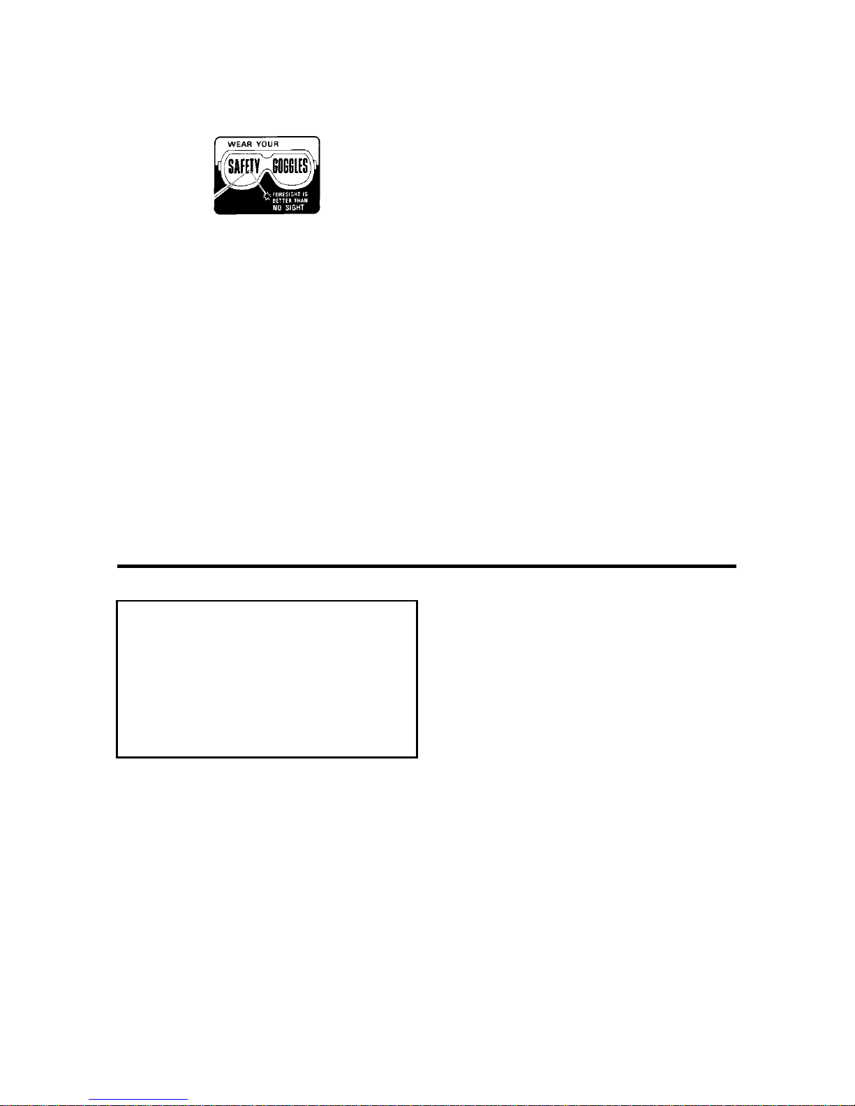
wear safety goggles, not glasses
complying with ANSI Z87.1 (or in
Canada CSA Z94.3-99) shown on
package. Everyday eyeglasses
have only impact resistant lenses.
They are not safety glasses. Safety
goggles are available at many local
6
retail stores. Glasses or goggles not
in compliance with ANSI or CSA
could seriously hurt you when they
break.
• For dusty operations, wear a dust
mask along with safety goggles.
Plan the way you will push the
workpiece through.
• Never pull the workpiece through.
Start and finish the cut from the front
of the table saw.
• Never put your fingers or hands in
the path of the sawblade or other
cutting tool.
• Never reach in back of the cutting
tool with either hand to hold down
workpiece, support the workpiece,
remove wood scraps, or for any
other reason.
• To reduce the risk of hand positions
where a sudden slip could cause fingers or hand to move into a sawblade or other cutting tool.
• Don’t overreach. Always keep good
footing and balance.
• Push the workpiece against the
rotation of the blade, never feed
materi al into the cutting t ool from th e
rear of the saw.
• Always push the workpiece all the
way past the sawblade.
• As much as possible, keep your
face and body to one side of the
sawblade, out of line with a possible
kic kback or thr o w b ack.
• Set the cutting tool as low as possible for the cut you’re planning.
Reduce the Risk of Accidental
Starting
• Make sure switch is “OFF” before
plugging saw into a power outlet.
Whenever Sawblade Is Spinning
WARNING: Don’ t allow familiarity
(gain ed f rom f requent use of
your table saw) to cause a careless mistake. Always remember
that a careless fraction of a second is enough to cause a severe
injury.
• Before actually cutting with the saw,
watch it while it runs for a short
while. If it makes an unfamiliar noise
or vibrates a lot, stop immediately.
Turn the saw off. Unplug the saw.
Do not restart until finding and correcting the problem.
• Make sure the top of the arbor or
cutting tool turns toward the front of
the saw.
Keep Children Away.
• Make sure bystande rs are clear of
the table saw and workpiece.
Don’t Force Tool.
• Let the blade reach full speed
before cutting.
• It will do the job better and safer at
its designed rate.
• Feed the workpiece into the saw
only fast enough to let the blade cut
without bogging down or binding.
Before freeing jammed material.
• Turn switch “OFF”.
• Wait for all moving parts to stop.
• Unplug the saw.
• Check blade, spreader and fence
for proper alignment before starting
again.
• Keep all visitors a safe distance
from the table saw.
7
Safety Instructions For Table Saws (continued)
• To reduce the risk of throwback of
cut off pieces.
• Use the guard assembly.
T o remove loose pieces beneath or
trapped inside the guard.
• Tur n saw “OFF”.
• Remove switch key.
• Wait for blade to stop before lifting
the guard.
Additional Safety Instructions For:
Rip Type Cuts.
• Never use the miter gauge when ripping.
• Use a push stick whenever the
fence is 2 inches or more from the
blade.
• When thru-sawing, use an auxiliary
fence and push block whenever the
fence must be between 1/2 and 2
inches from the blade.
• Never thru-saw rip cuts narrower
than 1/2 inch. (See “Basic Saw
Operations-Ripping and Bevel Ripping” sections.)
• Never rip anything shorter than 10”
long.
• When using a push stick or push
block, the trailing end of the board
must be square. A push stick or
block against an uneven end could
slip off or push the work away from
the fence.
• A Featherboard can help guide the
workpiece. (see ”Basic Saw Operation-Using Featherboards for ThruSawing.” section)
• Always use featherboards for any
non thru rip type cuts. (See “Basic
Saw Operations - Using Featherboards for Non-Thru Sawing” section).
Before Leaving The Saw.
• Turn the saw off.
• Wait for blade to stop spinning.
• Unplug the saw.
• Make workshop child-proof. Lock
the shop. Disconnect master
switches. Remo ve the yellow swi tch
key. Store it away from children and
others not qualified to use the tool.
Featherboard
See “Work Feed Devices” section for
Material and Dimensions
Before Starting.
• To reduce the risk of kickbacks and
slips into the blade, make sure the
rip fence is parallel to the sawblade.
• Before thru-sawing, check the antikickback pawls. The pawls must
stop a kickback once it has started.
Replace or sharpen anti-kickback
pawls when points become dull.
(See “Maintaining Your Table Saw Anti-Ki ckb ack Pa wls” section.)
• Plastic and com position (like hardboard) materials may be cut on your
saw. However, since these are usually quite hard and slippery, the antikickback pawls may not stop a kickback. Therefore, be especially careful in your setup and cutting
procedures.
While Thr u-sa wing.
• To reduce the risk of kickbacks and
slips into the blade, always push forward on the section of the workpiece between the sawblade and
the rip fence. Never push forward on
the piece being cut off.
8
Additional Safety Instructions For:
Crosscut Type Cuts.
• Never use the rip fence when crosscutting.
• An auxiliary wood facing attached to
the miter gauge can help prevent
workpiece twisting and throwbacks.
Attach it to the slots provided. Make
the facing long enough and big
enough to support your work. Make
sure, however, it will not interfere
with the sawblade guard.
Before Starting
• Use jigs or fixtures to help hold any
piece too small to extend across the
full length of the miter gauge face
during the cut. This lets you properly
hold the miter gauge and workpiece
and helps keep your hands away
from the blade.
While Cutting
• To reduce the risk of blade contact,
always hold the miter gauge as
shown in “Basic Saw Operations Using The Miter Gauge”.
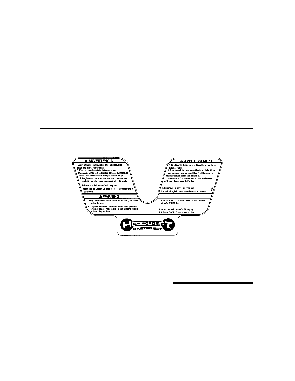
Additional Safety Instructions For Herc-U-Lift™ Caster System:
Before Using the Caster System
Read the following warning located on the plate assembly:
To reduce the risk of injury from
unexpected tool movement.
• Check to make sure tool does not
move prior to use. If tool moves,
adjust all four leveler feet to support
Glossary of Terms for Woodworking
Anti-Kickback Pawls
Device which, when properly maintained,
is designed to stop t he workpiece from
being thrown towar ds the front of the saw
at the operator during ripping operation.
Arbor
The shaft on which a cutting tool is
mounted.
Bevel Cut
An angle cutting operation made through
the tool.
• Put the tool on a firm level surface
where there is plenty of room to
handle and properly support the
workpiece.
the face of the workpiece.
Compound Cut
A simultan eous bevel and mite r crosscutting operation.
Crosscut
A cutting opera tion made across t he width
of the workpiece.
Dado
A non thru cut which produces a square
sided notc h or trough in the workpiece.
9

Glossary of Terms for Woodworking (continued)
Featherboard
A device which can help guide workpieces during ri p type operation.
Freehand
Performing a cut without the use of fence
(guide), mit er gauge, fix ture, hold down or
other proper device to prevent the workpiece from twisting during the cutti ng
operation. Twisting of the workpiece can
cause it to be thrown.
Gum
A sticky, sap based residue from wood
products.
Heel
Misalignmen t of the sawblade such that
the blade is n ot parallel t o the mit er gaug e
groove.
Kerf
The amount of material removed by the
blade in a through cut or the slot produced
by the bl ade in a nonthrough or par tial cut.
Kickback
An uncontrolled grabbing and throwing of
the workpiece ba ck t oward t he front of t he
saw.
Leading End
The end of the workpiece whi ch, during a
rip type operati on, is pushed into the cutting tool first.
Miter Cut
An angle cutting operation made across
the width of the workpiece.
Molding
A non through cut which produces a special shape in the work piece used for join-
ing o r decor a tion.
Ploughing
Grooving with the grain the length of the
workpiece, using the f ence. (A type of
non-through cut.)
Push Stick
A device used to feed th e workpiece
through the saw during narrow ripping
type opera tions which helps keep the
operator’s hands well away from the
blade.
Push Block
A device used for ri pping type operation s
too narro w to allow use of a push stick.
Rabbet
A notch in the edge of a workp iece. (A
type of non-through cut)
Resin
A sticky, sap based substance that has
hardened.
Revolutions Per Minute (RPM)
The number of tur ns com pleted by a spinning object in one minute.
Rip Cut
A cutting oper atio n along th e length o f the
workpiece.
Sawblade Path
The area of the workpiece or table top
directly in line with either the travel of the
blade or the part of the workpiece which
will be, or has been, cut by the blade.
Set
The distan ce that the tip of the sawblade
tooth is bent (or set) outward from the
face of the blade.
Molding
Bevel Cut
Kerf
Compound
Cut
Cross Cut
Miter Cut
10
Rip Cut
Dado or
Ploughing
Rabbet

Throw-Back
Trailing End
Throwing of pieces i n a mann er si m il ar to
a kickback.
Thru-Sawing
Any cutting operation where the blade
extends completely thr ough the thickness
of the workpiece.
The workpi ece end l ast cu t by the blade i n
a ripping operation.
Workpiece
The it em on which the cutti ng operation is
being performed. The surfaces of a workpiece are commonly referred to as fa ces,
ends, and edges.
Motor Specifications and Electrical Requirements
Power S upply and Mot or
Specifications
WARNING: To reduce the risk of
electrical hazards, fire hazards or
damage to the tool, use proper
circuit protection. Your tool is
wired at the factory for operation
using the voltage shown. Connect tool to a power line with the
appropriate voltage and a 15amp branch circuit. Use a 15amp time delay type fuse or circuit breaker. T o reduce the risk of
shock or fire, if power cord is
worn or cut, or damage d in any
way, have it replaced im m ed iately.
The A-C motor used on this tool is a
capacitor start, capacitor run non-reversible type, having the following specifications. It is wired at the factory for
operation on 110-120v AC, 60 Hz. service.
Wired for
120V
Rated H.P 1-1/2 1-1/2
Voltage 110-120 220-240
Amperes 13 6.5
Hertz
(Cycles)
Phase Single Single
RPM 3450 2875 (50 Hz)/
Rotation of
Shaft
60 50/60
Clockwise Clockwise
Wired for
240V
3450 (60 Hz)
General Electrical Connections
DANGER: To reduce the risk of
electrocution:
1. Use only identical replacement parts when servicing.
Servicing should be performed by a qualified service
technician.
2. Do not use in rain or where
floor is wet.
This tool is intended for
indo or residenti al use only.
WARNING: Do not permit fingers
to touch the terminals of plug
when installing or removing the
plug to or from the outlet.
11
Motor Spec ifica tions a nd Electr ical Re qu iremen ts ( contin ued )
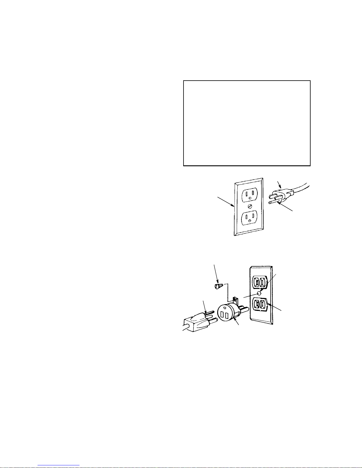
110-120 Volt, 60 Hz. Tool Information
The plug supplied on your tool may not fit
into the outlet you are planning to use.
Your local electrical code may require
slightly di fferent power cord plug connections. If the se differences exist refer to
and make the proper adj ustments per
your local code before your tool is
plugged in and turned on.
In the event of a malfunction or breakdown, grounding provides a path of least
resistance for electric current to reduce
the risk of electric shock. This tool is
equipped with an electric cord having an
equipment-g rounding conductor and a
grounding plug, as shown. The plug must
be plugged into a matching outlet that is
properly installed and grounded in accordance with all local codes and ordinances.
Do not modify the plug provided. If it will
not fit the outlet, have the pr oper outlet
installed by a qual ified electrician.
A temporary adapt er may be used to connect this plug to a 2-prong outlet as
shown if a properly grounded three prong
outlet is not available. This tempor ary
adapter should be used only until a properly grounded three prong outlet can be
installed by a qual ified electrician. The
green colored rigid ear, lug or the like,
extending from the adapter must be connected to a permanent ground such as a
properly grounded outlet box.
Improper connec tion of the equipmentgrounding co nductor can r esult in a ri sk of
electric shock. The conductor with insulation having an outer surface that is green
with or without yell ow str ipes is the equipment-groundi ng conductor. If rep air or
replacement of the electric cord or plug is
necessary, do not connect the equi pmentgrounding cond uctor to a live terminal.
If the grounding instructions are not com-
pletely understood, or if you ar e in doubt
as to whether the tool is properly
grounded check with a qualified ele ctr ician or service personnel.
WARNING: If not properly
grounded, this tool can cause an
electrical shock, particularly
when used in damp locations, in
proximit y to pl um bi ng, or out of
doors. If an electrical shock
occurs there is the potential of a
secondary hazard, suc h as your
hands contacting the sawblade.
Properly
Grounded
3-Prong Outlet
Grounding Lug
3-Prong
Plug
Adapter
NOTE: The adapter il lustrated is for use
only if you already have a properly
grounded 2-prong outlet.
NOTE: In Canada the use of a temporary
adapter is not permitted by the Canadian
Electrical Code.
3-Prong Plug
Grounding
Prong
Make sure this
Is Connected
to a Known
Ground
2-Prong
Outlet
12
Changing Motor Voltage
WARNING: Electric shock can
kill. To reduce the risk of shock,
never connect plug to power
source outlet until all assembly
steps are completed. Unplug saw
before making or changing any
connections.
NOTE: Power cord lead connections for
110/120 volt and 220/240 volt applications
are the same. This will show how to
change the internal motor wiring to convert
saw from a 120V to a 240V application.
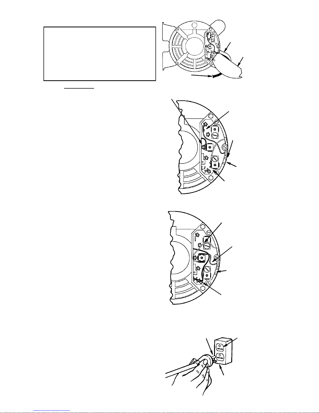
1. Open the motor connector box cover
located on the end of motor using a flat
blade screwdr iver to loosen screws.
2.From the factory this motor is connected
for 120V usage. F or 240V usage:
a. Remove the brown motor lead from
terminal #3 and attach it to the “P”
(parking position) plastic terminal.
NOTE: This brown lead is not
required for the 240 volt application
and is “parked” in the plastic “P” terminal to keep it insulated. Be sure the
brown lead is attached securely to
the “P” terminal holde r.
b. Remove the yellow motor lead from
terminal #4 and attach it to terminal #3.
c. Remove the red motor lead from termi-
nal #2 and attach it to terminal #3.
d. Cut off the 120 volt power cord plug
and replace it with a (3 blade) 240 volt
15 amp U.L. listed plug. (See illustration of 240V plug & receptacle.) Connect the power cord white and black
leads, respectively, to the “hot” plug
blade terminals and connect the power
cord green grounding wire to the plug
ground prong terminal.
3. Close motor connec to r box bein g s ure t hat
the power cord is seated in the strain rel ief
groove and t ight en bo x cover screws .
4.Plug your saw into a 220-2 40V, 15amp,
3 blade recept acle.
5. Make certain the receptacle is connected
to a 240V A.C. power supply through a
240V branch circuit having at least a 15
amp capacity and protected by a 15 amp
time-delay fuse or circuit breaker.
To Switch
Box
Brown Motor
Lead On
Terminal #3
220/240 Volt Connection
Power
Cord
Connector
Box Cover
110/120 Volt Connection
(As Received From Factory)
Red Motor
Lead on
Terminal #2
NOTE: Power
Cord Not
Shown For
Clarity
Cord Exit/
Strain Reli ef
Groove
Yellow Motor Lead
On Terminal #4
Yellow Motor
Lead on
Terminal #3
Red Motor
Lead on
Terminal #3
Cord Exit/
Strain Relief
Groove
Brown Motor
Lead on
Terminal “P”
(Plastic)
Grounding
Prong
Grounded
Outlet Box
220-240V
15 Amp 3 Blade
Receptacle
13
Motor Spec ifica tions a nd Electr ical Re qu iremen ts ( contin ued )
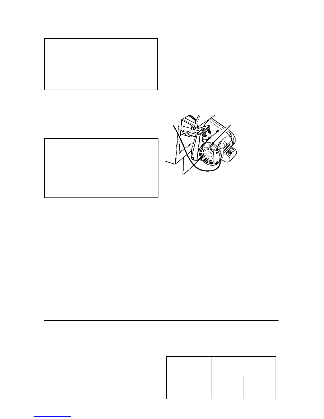
Motor Thermal Overload Protector
CAUTION: To reduce the risk of
motor damage, this motor should
be blown out or vacuumed frequently to prevent sawdust
buildup which will interfere with
normal motor ventilation .
Y ou r saw is equi pped wit h a manual-r eset
thermal-overload protector designed to
open the power line circuit when the
motor temperature exceeds a safe level,
when motor is overload ed or when a lo w
voltage condition exists.
WARNING: To reduce the risk of
thrown objects or blade contact
from unexpected starting. If the
protector stops the saw motor,
immediately turn the saw switch
“OFF”, remove the key and allow
motor time to cool.
1.After cooling to a safe operating tem-
peratur e, t he overload protector can be
reset by pushing the red button on the
end of the motor. If the red button will
not click into place immediatel y, the
motor is still too hot and must be
allowed to cool for a while longer.
The time required for the motor to cool
may be equal to the length of time the
saw was used before the thermal overload protector opened. NOTE: An audible click wil l indicate the protector is
reset, push hard to hear the click.
2. As soon as the r ed button is rese t, the s aw
may be star ted an d ope ra ted nor mall y.
3.Frequent “blowing” of fuses or tri pping
of circuit breakers may result i f:
a.Motor is overloaded - Overloading
can occur if you feed too rapidly or if
saw is misaligned.
b. Motor circuit is fused differently from
recommendations - Always follow
instructions for the proper fuse/breaker.
Do not use a fuse/breaker of greater
capacity without consulting a qualified
electrician.
Manu al R es et
Button
c. Low voltage - Although the motor is
designed for operation on the voltage
and frequency specified on motor
nameplate, normal loads will be handled safely on voltage not more than
10% above or below the nameplate
voltage. Heavy loads, however, require
that voltage at motor terminals equals
the voltage specified on nameplate.
4.Most motor troubles may be traced to
loose or incorrect connections, overloading, reduc ed input vol tage (s uch as
small size wire in the supply circuit) or
to overly long supply circuit wire.
Always check t he connect i ons, th e load
and the supply circuit whenever motor
fails to perform satisfactorily. Check
wire sizes and length with the Wire Size
Chart below.
Wire Sizes
NOTE: Make sure the proper extension
cord is used and is in good condition.
The use of any extension cord will cause
some loss of power. To keep this to a minimum and to prevent ove rheating and
motor burn-ou t, use the t able shown to
determine the mini mum wire size (A.W .G.)
extension cord.
Use only 3-wire extension cords which have
3-prong grounding type plugs and 3-prong
receptacles which accept the tool’s plug.
Extension
Cord Length
110-120V 220-240V
0-25 Ft.
26-50 Ft.
14
Gauge
(A.W.G.)
14
12
18
18
Unpacking and Checking Contents
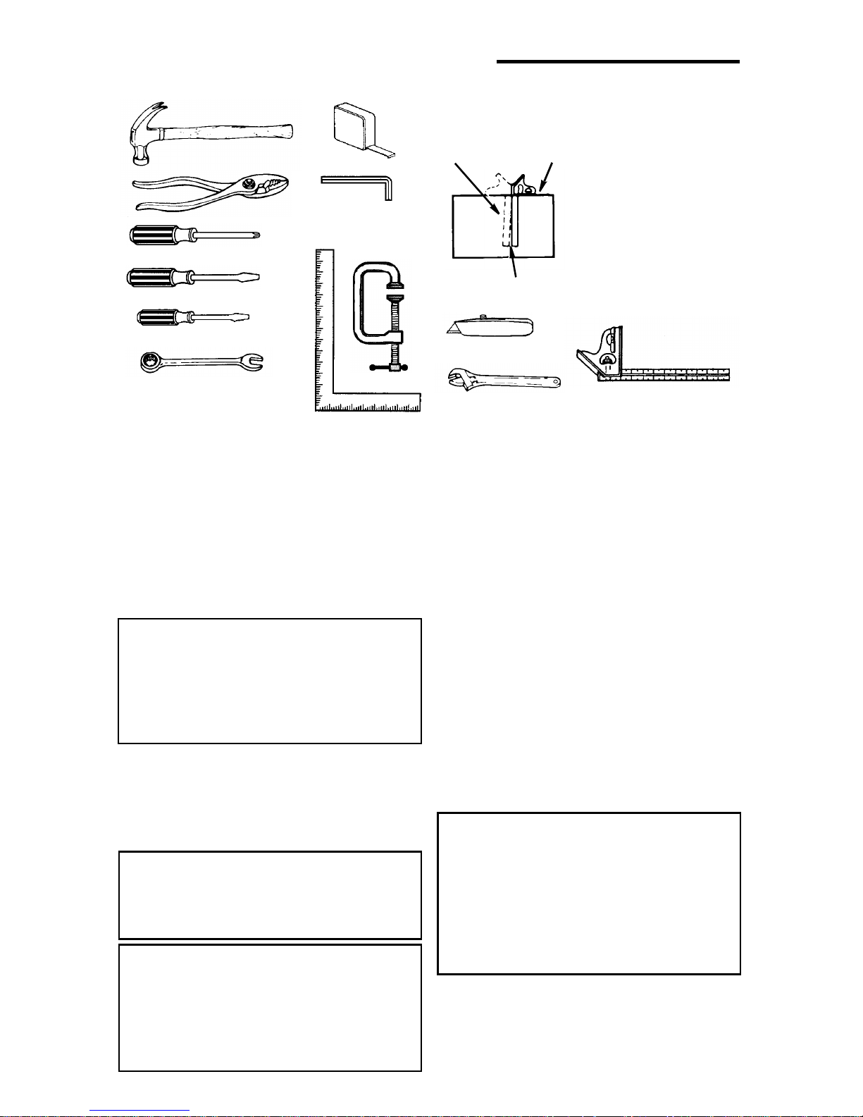
Tools Needed
Combination Square must be true. Check
it’s accuracy as shown below.
Draw light line on
Hammer
Ta pe Rule
board along edge
Select the straight edge of
3/4” thick board. This edge
must be perfectly straight.
Pliers
Phillips Screwdriver
Medium Screwdriver
Small Screwd river
Combination Wrenches
3/8 In., 7/16 In., 1/2 In.,
9/16 In., 3/4 In., 11/16 In.
Hex “L” Wrenches
2.5m m, 1/ 8 In .,
5/32 In., 3/16 In.
C Clamp
Framing Square
Unpacking
1.Sep ara t e saw an d a ll par t s f rom pac k ing
materials and check each one wit h the
illustration and the “List of Loose Parts”
to make certain all items are accounted
for , before discarding any packing material. Call 1-800-4-RIDGID or E-mail us at
inf o@ridgidwoodworking .com if any
parts are damaged or m issing.
WARNING: If any parts are missing, do not attempt to assemble
the table saw, plug in the power
cord or turn the switch on until
the missing parts are obtained
and are installed correctly.
2.Remove the protective oil that is
applied to the t able top and edges of
the table and tabl e exte nsions. Use a ny
ordinary household type grease and
spot remover.
WARNING: To reduce the risk of
fire or health hazard, never use
gasoline, naptha, or similar
highly volatile solvents.
WARNING: The saw is heavy. To
reduce the risk of back injury , get
help to lift the saw. Hold the saw
close to your body. Bend your
knees so you can lift with your
legs, no t your back.
NOTE: The square and
straight edge ar e us ed to
align the saw. They must
be accurate if the saw is
to be a ligned properly.
Should be no gap or overlap here when
square is flipped over in dotted position.
Utility Knife
Adjustable Wrench
Combination
Square
3.Apply coa t of paste wax t o the table and
table extensions.
NOTE: Before beginni ng assembly:
• Check that all parts are included. If you
are missing any part, do not assemble
the saw.
• Sometimes small parts can get los t i n
packaging mate rial. Do not throw away
any packaging unt il saw is put together.
Check packaging for missing parts
before contacting RIDGID.
• A complete parts list (Repair Parts) is at
the end of the manual. Use th is list to
identify the part number of the missing
part.
NOTE: At the begin ning of each ass embly
sectio n items such as nuts and bolts are
shown actual size.
WARNING: For your own safety,
never connect plug to power
source outlet until all assembly
steps are complete, and you
have read and understand the
safety and operating instructions.
15
Unpacking and Checking Contents (continued)
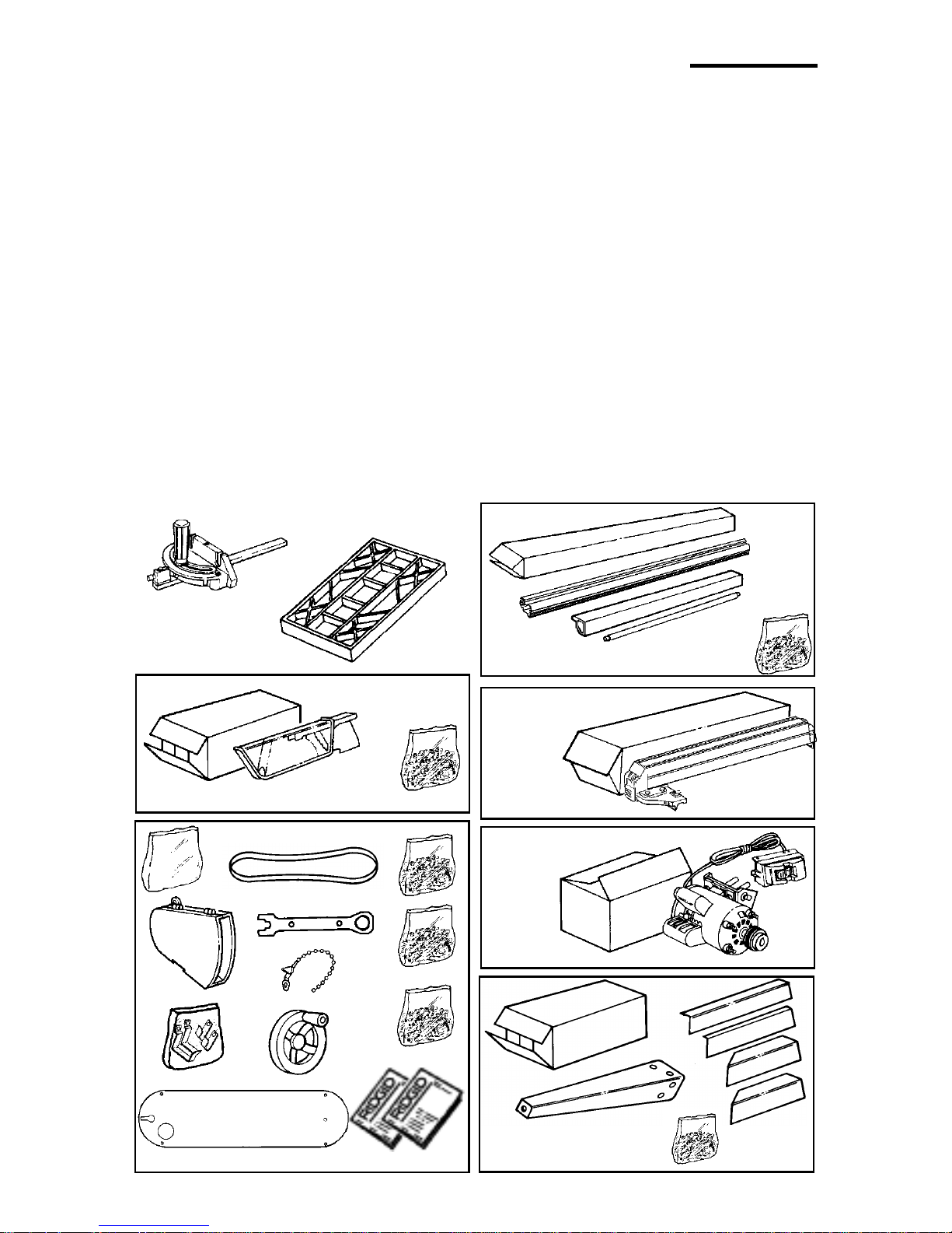
List of Lo ose P art s
Item Part Na me Qty.
A Mite r Ga ug e.....................................1
B Table Extension...............................2
Blade Guard Carton Containing:
C Blade Guard ..................... .. .......... .. .1
D Blade Guard Parts Bag......... .......... .1
Large Parts Bag Containing:
E Belt Guard .......................................1
F S to rage Hook Ba g ... .. ......................1
G Drive Belt .. ... ....................................1
H Blade Wrench............................ .. ....1
J Wire Tie ...........................................2
K Handwheel .......................................2
L Trim P a rt s B a g.. .. ... ..........................1
M Ta bl e Ex te n si o n Pa rts Bag ..............1
N Miscellaneous Parts Bag.................1
P Owners Manual (English)...... ..........1
Q Owners Manual (Spanish)...............1
DD Zero Clearance Table Insert ............1
Item Part Name Qty.
Fence Guide Bar Carton Containing:
R Front Fence Guide Bar.................... 1
S Re a r F e nce Gu i de Bar .... ................ 1
T Guide Bar Parts Bag .......................1
U Rod Support...... ............ .......... ........1
Rip Fence Carton Containing:
V Ri p F e nce.... ... ................................. 1
Motor Carton Containing:
W Motor/Switch Assembly...................1
Leg Stand Carton Containing:
X Leg .................................................. 4
Y Leg Brace (Long)..... .. ......................2
Z Leg Brace (Short)........................... .2
AA Si de Stringer ... .. ............................... 2
BB End Stringer (one w/label)...............2
CC Leg Stand Parts Bag........................1
A
Blade Guard Carton
G
E
H
J
B
C
D
M
R
S
Fence Guide Bar Carton
(Service #509469)
Rip Fence Carton
L
Motor Ca rton
U
T
V
W
F
DD
Large Parts Bag
K
N
Y
Z
P
Q
X
CC
Leg Stand Carton
16
AA
BB
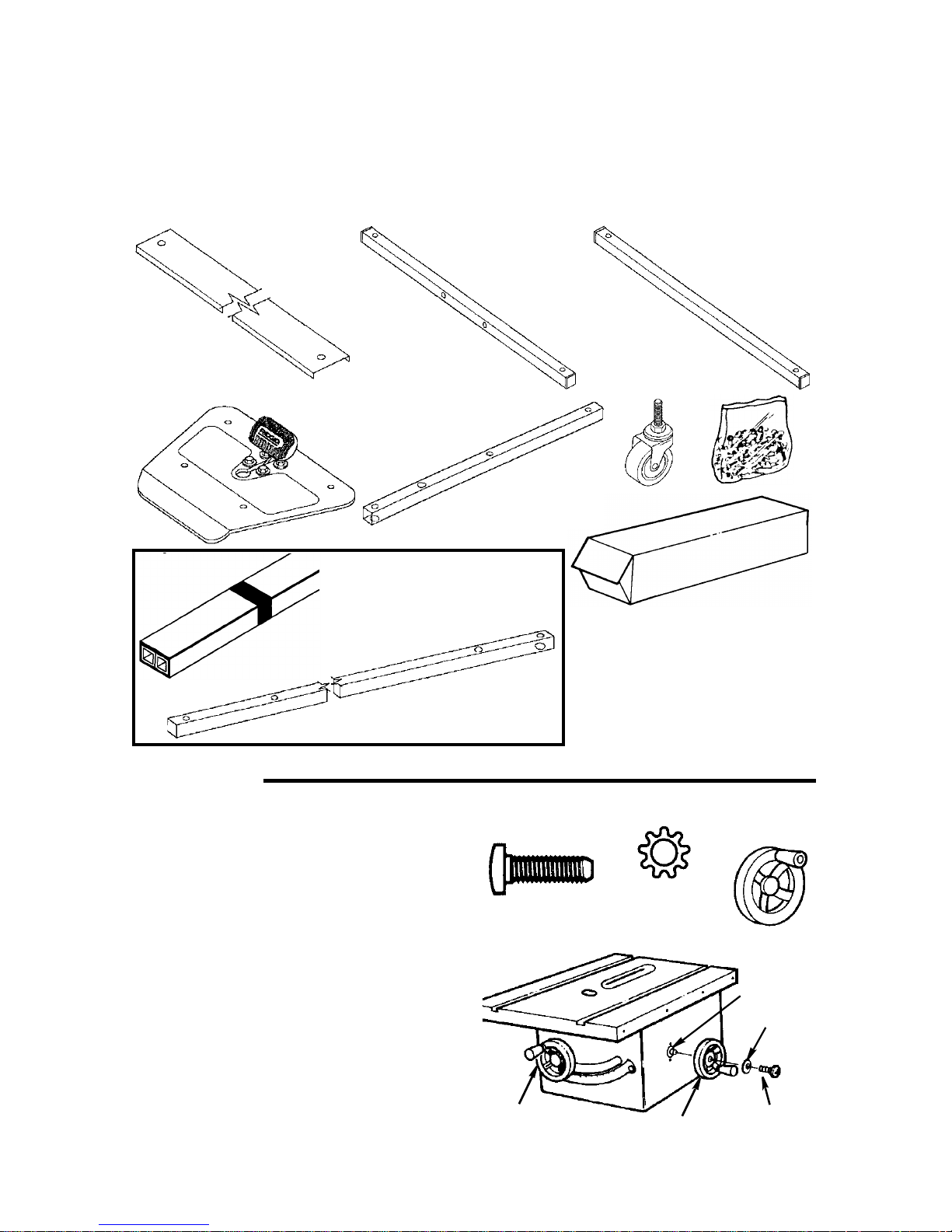
Herc-U-Lift™ Caster Carton
Item Description Qty.
A Channel Rear .................................1
B Tube U-Bo lt 1 9- 5 /8 " L ong ......... .......1
C Tube Support 17-1/4" Long .............1
D Plate Assemb ly... ... .. ........................1
Loose Part s
AB C
Item Description Qty.
E Tube Front 13-7/8" Long ................ .2
F Caster Swivel 3" .............................. 4
G Tube Rear 27" Lon g ..... ...................2
H Bag Loose Parts..............................1
DE
G
Item G packed separately in
main table saw box
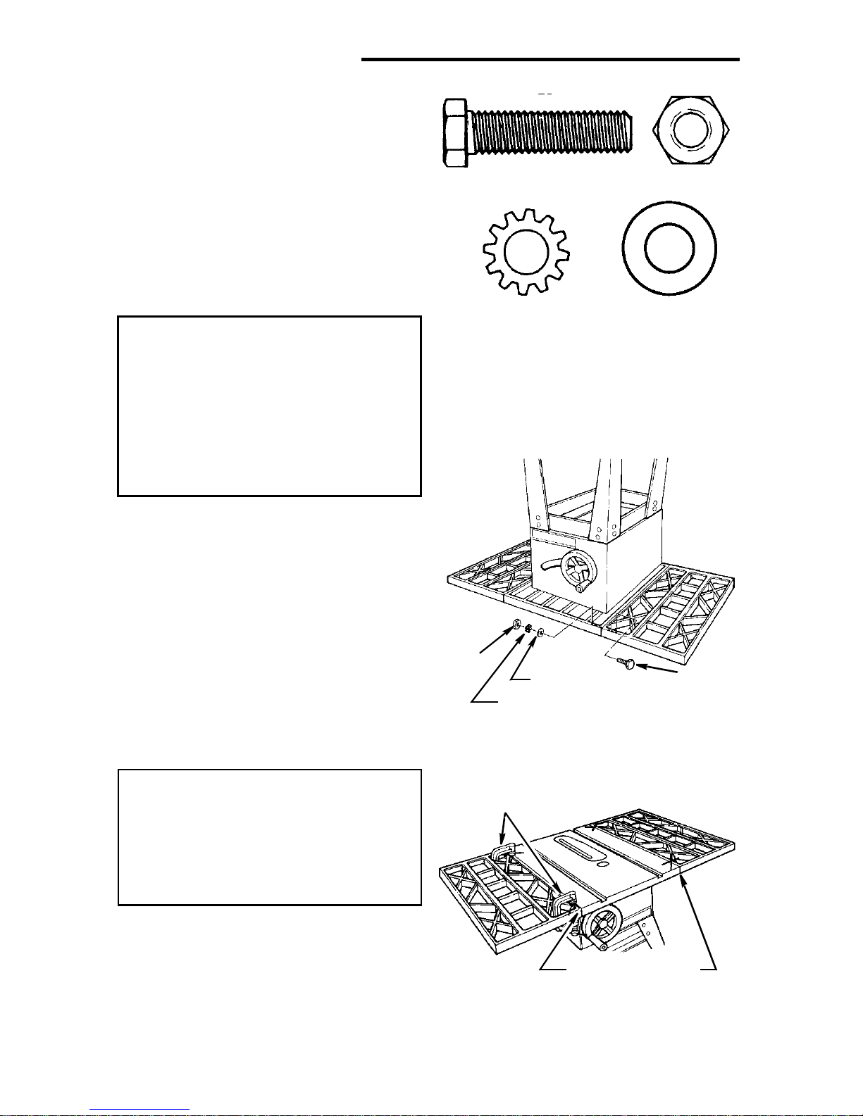
Assembly
Installing Handwheels
1.From the bag labeled “Miscellaneous”
remove only th e following hardware:
2 Pan Head Screws, 10 - 32 x 5/8" long
2 Lockwashers, #10 External Type
From among the loos e parts f ind the fol-
lowing:
2 Handwheels
2.Line up flat spots on shaft and hand-
wheel, push han dwheel onto shaft.
Install screw and lockwasher to lock
handwheel on shaf t. Repeat for the
other handwheel.
10-32 x 5/8
Pan Head Screw
Elevation
Handwheel
F
#10 Ext er na l
Lockwasher
Bevel
Handwheel
H
Handwheel
Shaft
Lockwasher
Pan Head
Screw
17
Assembly (continued)
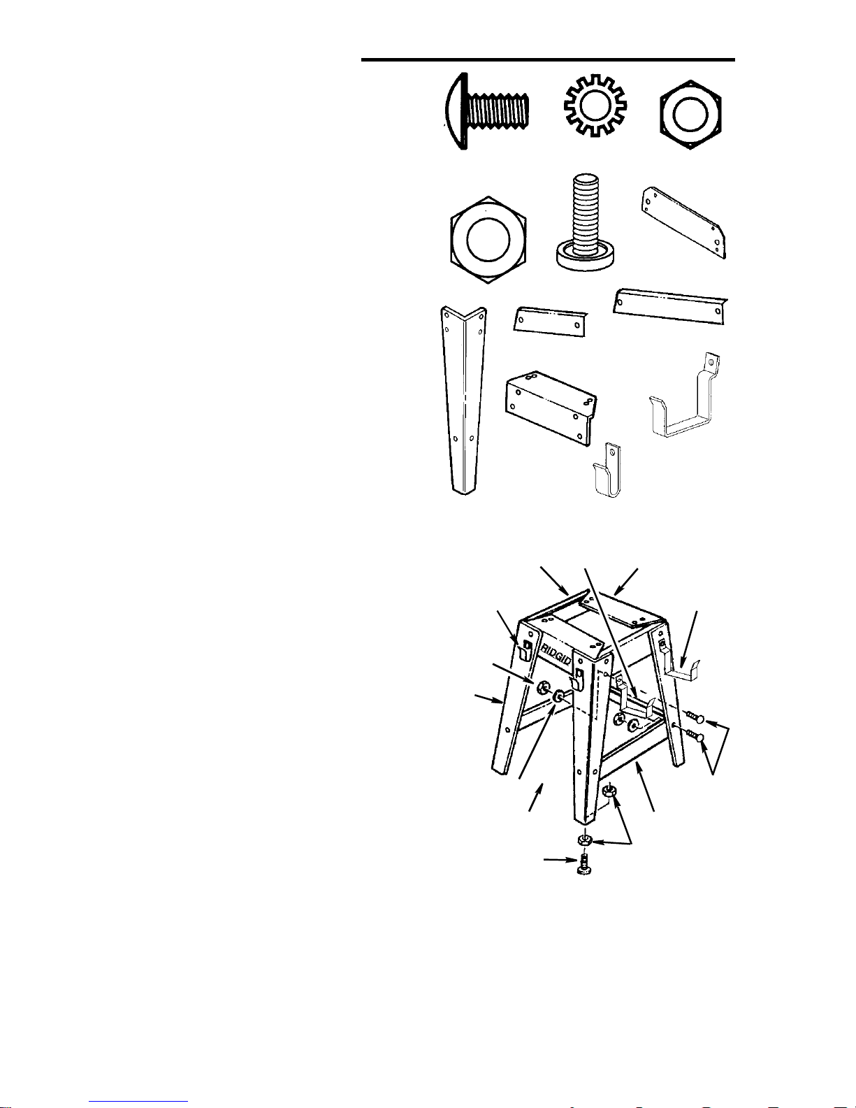
Assembling Leg Stand
1. Locate the carton containing the leg
stand.
Remove all parts from packing material.
2.From the bag labeled “Legs” remove
the followi ng hardware:
22 Truss Head Screws, 1/4-20 x 1/2”
long
22 Lockwashers, 1/4” External Type
22 Hex Nuts, 1/4-20
4 Leveling Feet
8 3/8-16 Hex Nut
From leg stand carton find the following:
4Legs
2 End Stringers
2 Side St ringers
3 Leg Braces (Two Long , One Short )
3. From amon g the loos e pa r ts f in d t h e f o l lowing:
2 Miter Gauge Storage Hooks
2 Rip Fence Storage Hooks
4.Assemble the l egs as shown.
Insert the truss head screws through
the holes in the legs, then through the
holes in the side and end stringers.
Attach miter gauge and rip fence storage hooks as shown.
Legs must be assembled on top of
stringers
5.Instal l t he lockwashers. Screw on the
nuts hand tight.
6.Insert the truss head screws t hrough
the holes in the l egs, then through the
holes in the leg br aces. Place short leg
brace on opposite side of RIDGID logo
as shown.
7.Instal l t he lockwashers. Screw on the
nuts but do not tighten until completely
assembled.
8.Instal l levelin g feet through holes in bottom of l egs as sho wn. Adjust fee t all t he
way up to bottom of leg.
9. Once you have completed the entire
assembly process, move saw to desired
loc ati o n a nd ad j ust t he f o ur l e vel in g f e et
1/4-20 x 1/2 In
Truss Head
Screw
3/8-16 Hex Nu t
End String ers
Leg
Side Stringers
Miter Gauge
Storage Hook
1/4-20
Hex Nut
Legs
Lockwasher
Herc-U-Lift
System Will Be
Installed Here
Leveling Foot
1/4 In External
Lockwasher
Leveling Foot
Leg Brace
(Short)
Miter Ga u g e
Storage Hooks
Leg Brace
(Short)
Stringer
Leg Br as es
(Long)
Rip Fence
Storage Hooks
End Stringers
Rip Fence
Storage Hook
Tru ss H e ad
Leg Brace
(Long)
3/8-16
Hex Nuts
to support the tool as follows:
a.With 9/16" wrench loosen bottom nut.
b. Back off top nut by hand.
c. Raise or lower foot by adjusting bottom
nut using 9/16" wrench.
d. Snug top nut against inside of leg by
hand.
e. Tighten all four bottom nuts using 9/16"
wrench.
18
1/4-20
Hex Nut
Side
Screw
Mount i ng Your Saw
1.From the bag labeled “Legs” remove
the followi ng hardware:
4 Hex Head Screws, 5/16-18 x 1-1/4"
Long
4 Hex Nuts , 5/ 1 6- 1 8
4 Lockwashers, 5/16" External Type
8 Flat Washers, 11/32 x 11/16 x 1/16
2.Place the saw upside down onto a
smooth piece of cardboard or heavy
paper, on the floor , so the saw i s rest ing
on the table top.
WARNING: The saw is heavy. To
reduce the risk of back injury , get
help to lift the saw. Hold the saw
close to your body. Bend your
knees so you can lift with your
legs, no t your back.
3.Place legs on saw so that holes in saw
base and leg set line up and trim label
is facing front.
4.Install screw, washers, lockwasher and
nut as shown.
5.Tighten all leg assembly and mounting
hardw a re at th is time .
5/16-18 x 1-1/4 In
Hex Head Screw
5/16 In External
Lockwasher
Cardboard
5/16-18
Hex Nut
11/3 2 I. D.
Flat Washer
Leg Set
Hex Nut
Lockwasher
Flat Washer
End Stiffener
Flat Washer
Hex Head Screw
Saw Base
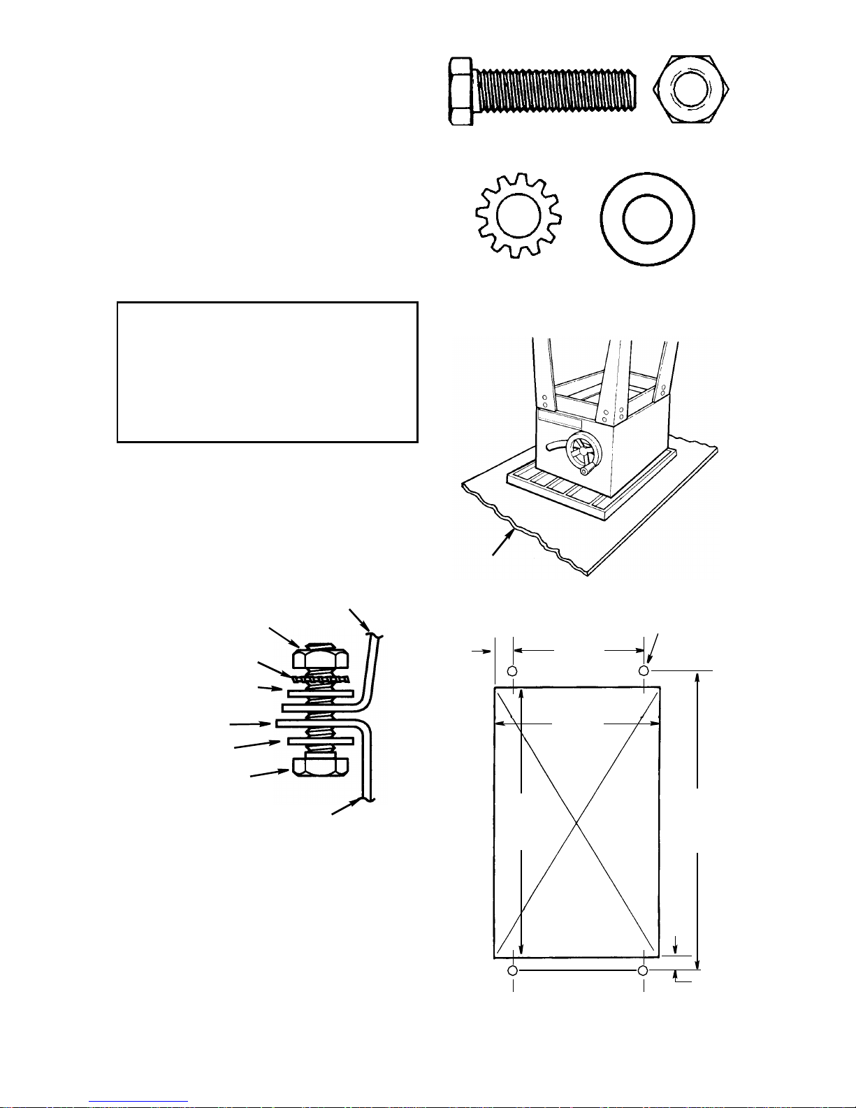
Bench Mounting
If you do not use the legset and mount the
saw on a bench, make sure that there is
an opening in the top of the bench the
same size as the openi ng in the bottom of
the saw so that the sawdust can drop
through. Recommended working height is
33 to 37 inches from the top of the saw
table to the floo r.
Moun ting Holes
7/8
+
15-3/4
+
NOTE: All dimensions in inches
11-1/4
13
Bench
Opening
Front of Saw
7/16 Dia.
+
16-3/4
+
1/2
19
Assembly (continued)
Assembling Table Extensions
1.From the bag labeled “Table Extensions” remove the following hardware:
(Quantity indicated is for two extensions)
8 Hex Head Screws, 5/16-18 x 1-1/4"
Long
8 Flat Washers, 11/32 x 11/16 x 1/16
8 Lockwashers, 5/16" External Type
8 Hex Nuts , 5/ 1 6- 1 8
NOTE: Assemble with saw upside down.
WARNING: Stock table extensions must be installed. They
help support the fence gu i de
bars. An unsupported guide bar
can twist. Twisted guide bars can
misalign fence. A misaligned
fence can cause binding or kickback. You could be hit or cut.
5/16-18 x 1-1/4 In
Hex Head Screw
5/16 In External
Lockwasher
5/16-18
Hex Nut
11/32 I.D.
Flat Washer
2. Insert four (4) 5/16-18 x 1 in. long screws
through the holes in each extension.
3.Positi on extension against ta ble so
screws extend through hole in table.
4.Instal l f lat washers, lockwasher, and
nuts on the screws. With a 1/2 " wrench ,
snug the four nuts just enough to take
the play out between the table and
extension. Do not tighten.
5.Repeat steps 1-4 to install the othe r
extension.
6.Stand saw upri ght on legs. Roll saw
over onto front then up onto feet.
WARNING: The saw is heavy. To
reduce the risk of back injury , get
help to lift the saw. Hold the saw
close to your body. Bend your
knees so you can lift with your
legs, no t your back.
7.Line up the front edge of extensi on with
the front edge of the table. At the spots
marked “X” in the drawing, tigh ten a “C”
Clamp over the edge of table and
extensi on. Use a combination squar e to
check the alignmen t o f the f ront a nd top
edges nearest the “X”’s. Tighten the
two corner nuts only wi th a 1/2" wrench.
Nut
Lockwasher
Flat Washer
“C” Clamps
Align Fron t Edge s
NOTE: This assembl y may also be done
without the use of a “C” Clamp.
Hex
Screw
20
WARNING: Table extensions
must be installed. Front edge of
table and extensions must be
lined up . An unev en front edge
can twist the fence guide bar.
Twisted guide bars can misalig n
fence. A misaligned fence can
cause binding or kickback. You
could be hit or cut.
8. Tighten a “C” clamp over the edge of
table and extension at the center until
the extension is even with the table surface as shown. Tighten the two center
nuts with a 1/2" wrench.
9. Re peat s teps 7 an d 8 to align th e othe r
extension.
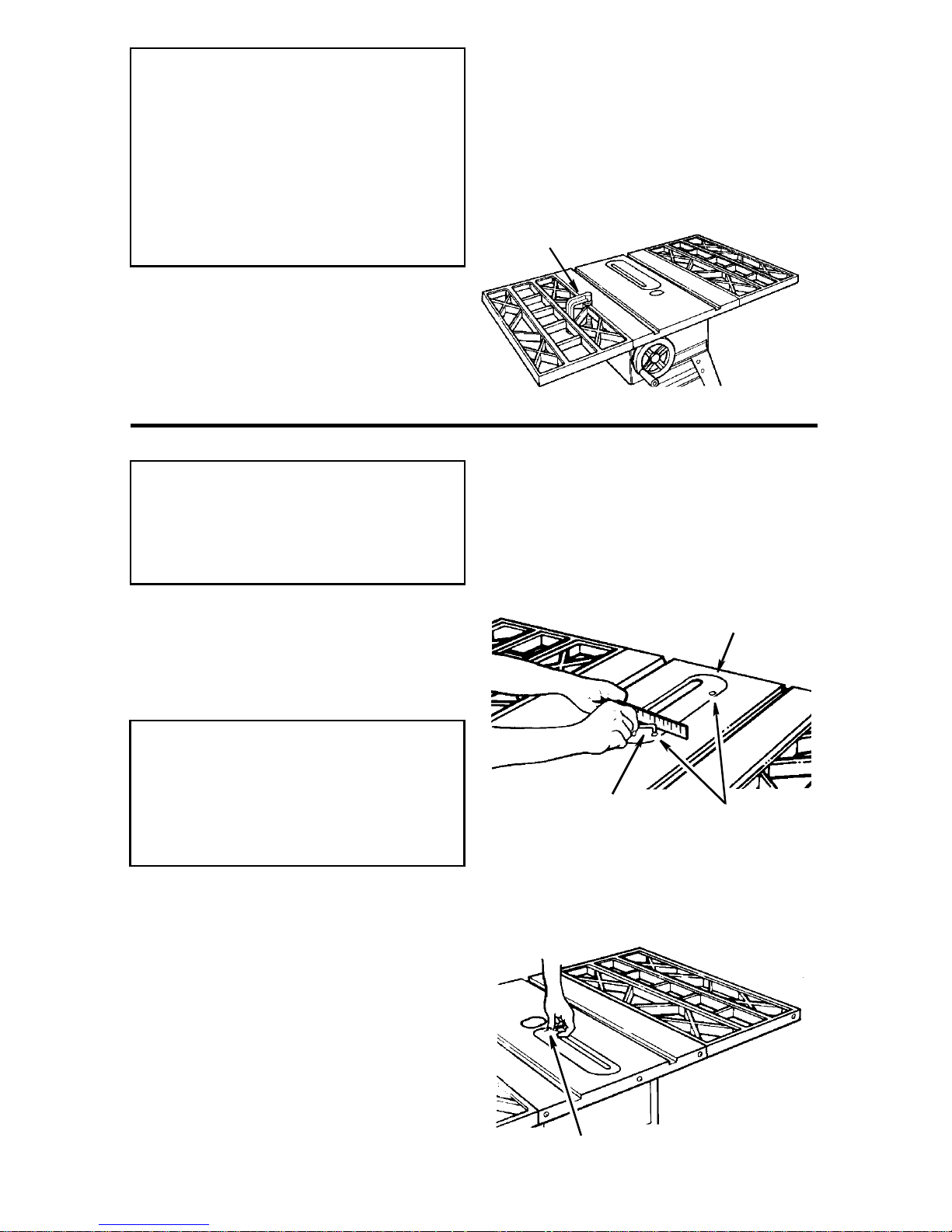
Checking Table Insert
WARNING: To reduce the risk of
injury from accidental start, make
sure switch is “OFF” and plug is
not connected to power source
outlet.
“C” Clamp
1.Insert should be flush with table top.
Check as shown. Loosen flat head
screw that holds insert and adjust the
four set screws as necessary. Tighten
flat head screw. Do not tighten screw to
the point where it bends the insert.
CAUTION: Insert must be even
with the table surface. Inserts too
high or l ow c an l et th e wor k pi ec e
“snag” or catch on uneven
edges. Workpiece could twist
and kickback.
2.To rem ove insert.
a.Make sure saw is off and unplugged.
b. Loosen flat head screw.
c. Lift insert from front end, and pull
toward fr o nt o f saw.
d. T o replace insert.
e. Make sure saw is off and unplugged.
f. Place insert into insert opening in table
and push toward rear of saw to engage
spring clip and until keyslot in insert will
drop over flat head screw. Tighten
screw .
g. Do not tighten screw to the point where
it bends the insert.
21
3/32 In.
Hex “L” Wrench
Fla t Head
Screw
Table I nsert
Set Screws
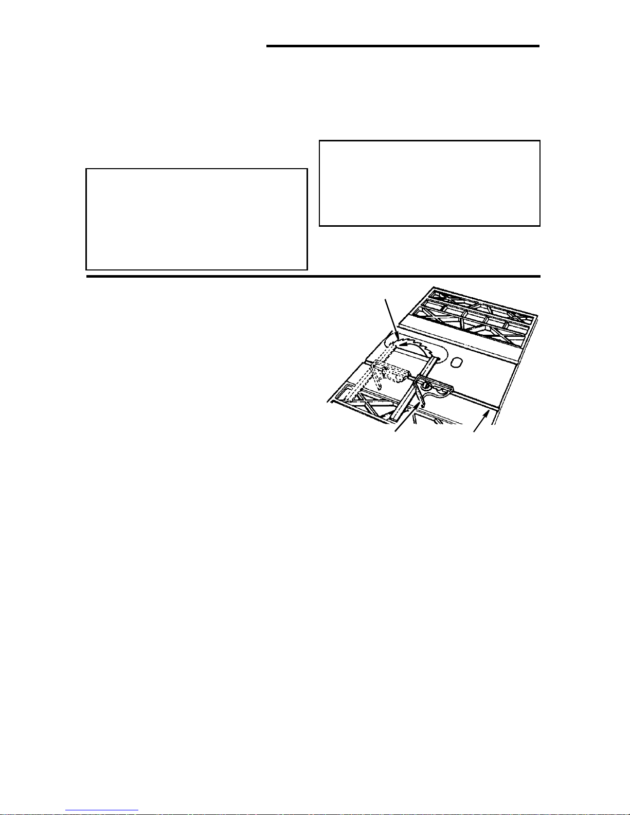
Assembly (continued)
Checking Heeling Adjustment or Parallelism of Sawblade to Miter Gauge
Groove
While cutting, the material mus t move in a
straight line parallel to the sawblade.
Therefore, both the miter gauge groove
and the rip fence must be parallel to the
sawblade.
WARNING: The blade must be
parallel to the miter gauge
groove. Misaligned b lades cou ld
bind on workpiece. Workpiece
could suddenly kickback. You
could be cut or hit.
To check for parallelism:
1.Raise blade to approximately 3" depth
of cut.
2.Mark an “X” on one tooth.
3.Place the head of a combination
square in the left miter gauge groove.
Rotate the blade so that the tooth
marked with an “X” is at the front and
adjust the blade of the square so that
it just touches the tip of the marked
tooth. Lock the square at this setting.
NOTE: Hold the head of the combina ti on
square firmly aga inst the edge of the miter
gauge groove during all measurements.
If the sawblade is not parallel to the miter
gauge groove, the blade will bind at one
end of the cut. This is known as “Heeling”.
WARNING: To reduce the risk of
injury from accidental start, make
sure switch is “OFF” and plug is
not connected to power source
outlet.
Sawblade
Combination
Square
Miter Gauge
Groove
4.Move the square to the rear of the
blade. Rotate the blade so the marked
tooth is at the rear and see if the
marked tooth again touches the blade
of the square.
5.If the marked tooth touches the square
at th e f ront a nd at the re ar of the s awblade, the blade is parallel to miter
gauge slot. The parallelism is correct.
Proc ee d to the “Checking Blade Tilt, or
Squareness of Blade to Table”.
6. If square does not touch the marked
tooth at the re ar an d front equa lly (gap
is greater that 0.015 inch–thickness o f
4 pages from Ow ners Manual) or t ooth
interferes with square, the m echanism
underneath must be adjusted to make
the blade parallel to the miter gauge
groove.
22
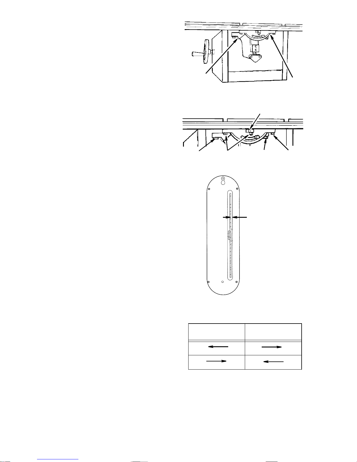
7. Tighten the tilt lock handle located at
the front of the saw.
8.Loosen the three mounting screws
that hold the front trunnion and the
three mounting screws that hold the
rear trunnion using a 9/16" wrench.
The front center trunnion bolt can be
accessed through the slot for the tilt
lock handle in the fr ont of the saw .
9. Check position of the sawblade in
the table insert slot. There should be
a minimum of 1/8" between the right
edge of the slot and the blade
(vie wed from re ar of sa w). Adj ust by
moving the front trunion. Secure by
lightly tightening the front trunion
center bolt.
10.Standing at the rear of the saw, determine which direction the rear of the
sawblade must move to make it parallel to the miter slot. To move the rear
of the blade to the right - turn the
micr o ad jus t lev er to t he le ft. To move
the rear of the blade to the left - turn
the micro adjust lever to the right.
11. Using the micro adjust lever move the
rear of the blade in the desired direction. Repeat steps 3 and 4 until blade
is parallel to miter gauge slot.
12.Securely tighten all six screws on the
rear and front trunnion using a 9/16"
wrench.
13.Recheck the marked blade tooth at
the front and rear position to insure
that the adjustment has not moved.
14.If the adjustment moved, loosen the
five bolts (all except front center) and
repeat steps 11-12.
15.When the adjustment is correct
securely tighten all six bolts on the
front and rear trunnion.
NOTE: Maintain a minimum 1/8 inch
clearance between the right side of the
blade and the table in sert (viewed from
rear of saw). T his in sur es clear ance when
the blade is beveled.
Front
Trunnion
Eccentric
Front
Trunnion
Screws
Rear
Trunnion
Screws
Front
Trunnion
Screws
1/8" Minimum
Clearance
Rear of
Saw
To Move Blade Move Lever
Rear
Trunnion
Lever
Rear
Trunnion
Screws
23
Assembly (continued)
Checking Blade Tilt, or Squareness
of Bla de to Table
When the bevel pointer i s pointing directly
to the “0” mark on the bevel scale, the
sawblade should make a square cut 90°
to the table.
WARNING: For your own safety,
turn switch “OF F” and remove
plug from po we r source outl et.
Tilt Lock Handle
To check for squareness, 90° position:
1.Raise blade to 3" depth of cut .
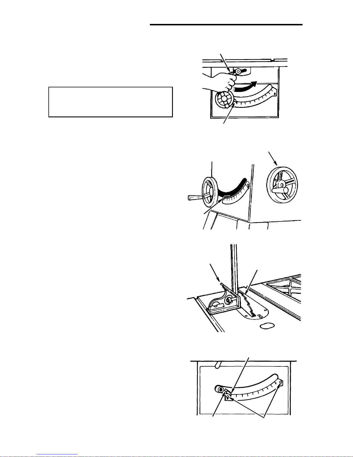
2.Operate the tilt lock handle (counter-
clockwise) to loosen t he tilt clamp
screw.
NOTE: Handle is spring loaded for
engagement with screw head - must be
pushed inward for disengagement
whenever necessary to obtain a new
grip on screw head. Always position
handle in downward position to prevent
binding when tilting the blade.
3.Rotate tilt handwheel clockwise a few
turns to til t bl ade. Now, r otate handwheel counterclockwise until it stops.
Blade should now be square with table
and pointer should point to “0”.
4.Place the square against blade. Mak e
sure square is not touching the tip of
one of the saw teeth.
Bevel Poin ter
Tilt Handwhe el
Pointer
Square
Blade
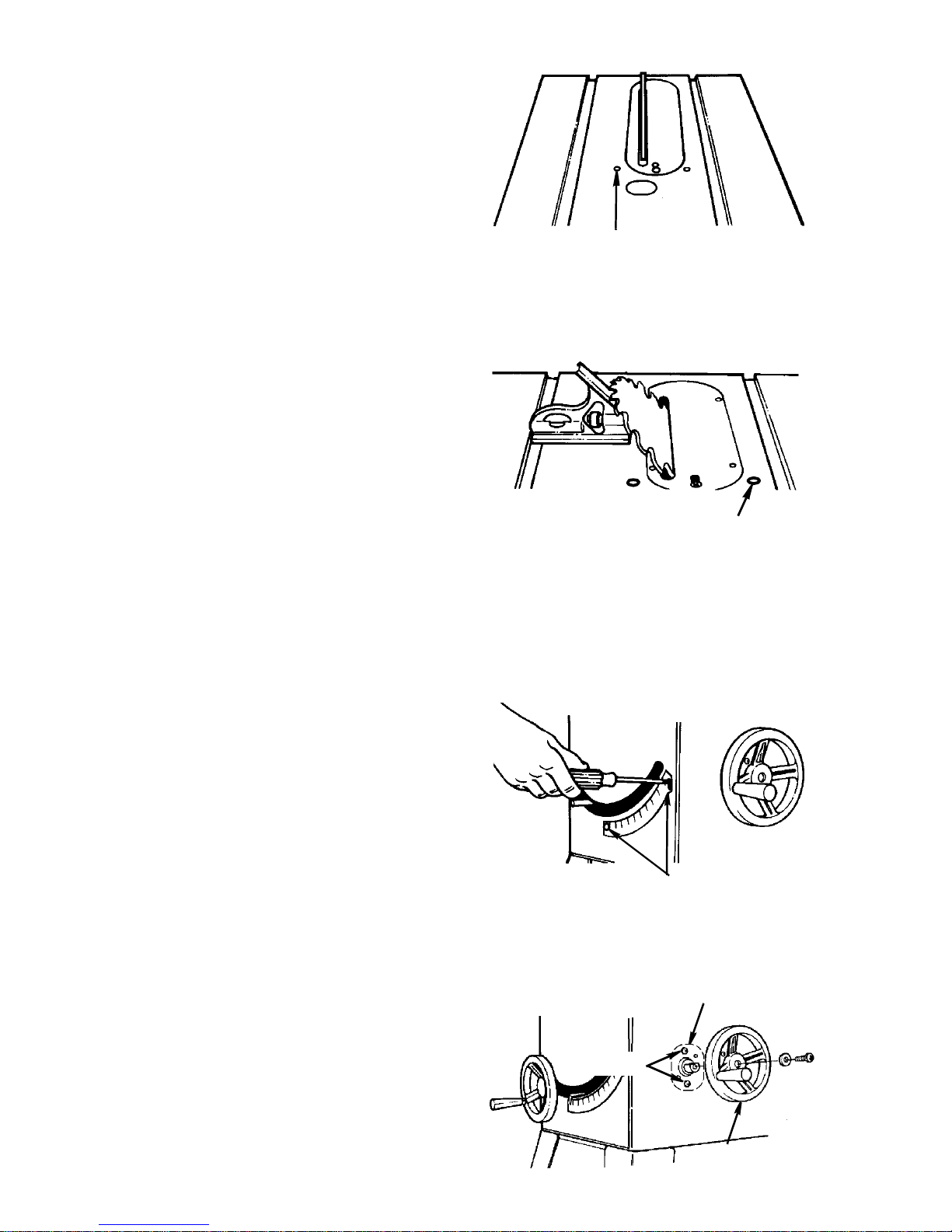
A.If blade is square to table
1.Check pointer. If pointer does not
point to t he “0” mark on the bevel
scale.
a. Remove elevation handwheel.
b. For gross adjustments bend the
pointer to align with the zero
mark. For fine adjustments
loosen the screw and adjust the
pointer using a medium screwdriver.
c. Install elevation handwheel.
Adjusting Screw
24
Pointer
Pointer at
0° Position
Scale Adjusting
Screw
B.If blade is not square to table...the
90° stop screw must be adjusted.
1.Use a 3/16" hex “L” wrench to
unscrew the 90° stop screw until it
is flush with the top of the table.
2.Turn tilt handwheel clockwise one
turn, then turn handwheel counter clockwise until blade is square
with table.
3.Screw 90° stop screw in until the
sawblade starts to move. Check
once again for squareness and
readjust screw, i f necessary.
4.Check pointer as described in step
A.
To check for alignment, 45° Position
1.Tilt blade to left as far as it will go.
2.Place an accurate square against
blade. Make sur e square is not touching the tip of one of the saw teeth.
A.If blade is 45° to table;
1.Check pointer. If pointer does not
point to the 45° mark on the scale,
the scale must be adjusted.
a. Remove elevation handwheel.
b. Loosen two screws on scale
and adjust scale up or down
until pointe r points to 45° mark.
c. Install elevation handwheel.
B. If blade is not 45° to table, stop
screw and scale mus t be adjusted .
1.Use a 3/16" hex “L” wrench to
unscrew the 45° stop screw until it
is flush with the top of the table.
2. Turn tilt handwheel until blade is
45° to the table.
3.Screw 45° stop screw in until the
sawblade starts to move. Check
once again and readjust screw, if
necessary.
4.Check pointer as described in step
A above.
Checking Tilt Mechanism
With tilt lock handle loosened, the handwheel should turn freely without binding.
The turning friction can be adjusted by
tightening or loosening the screws in the
bearing retainer.
NOTE: Tilt handwheel must be removed
to adjust. When adjusting the screws in
the bearing retai ner, hold the nut inside
using a 3/8 inch wrench.
90°
Stopscrew
45°
Stopscrew
Scale Screws
Retainer Bearing
(Inside Base)
Screws
Tilt
Handwheel
25
Assembly (continued)
Assembling Herc-U-Lift™ Caster
System
Assembly Tips
1.The caster set consi sts of an upper and
lower as s e mb ly.
2.First put the upper and lower assembly
together following instructions below.
3.Loosely assemble all nut and screw
connecti ons. After mount ing the ass emblies on the t able saw, adjust frames on
center, and then securely tighten all fasteners.
4.When assembl ing the frames, Tube
Rear (27" long) and Tube Front (13-7/8"
long) must be assembled so the la rge
hole faces down towards the floor. See
the illust ration before assembling.
Hex Head Screw w/Washer
1/4-20 x 1-1/2
Upper Assembly
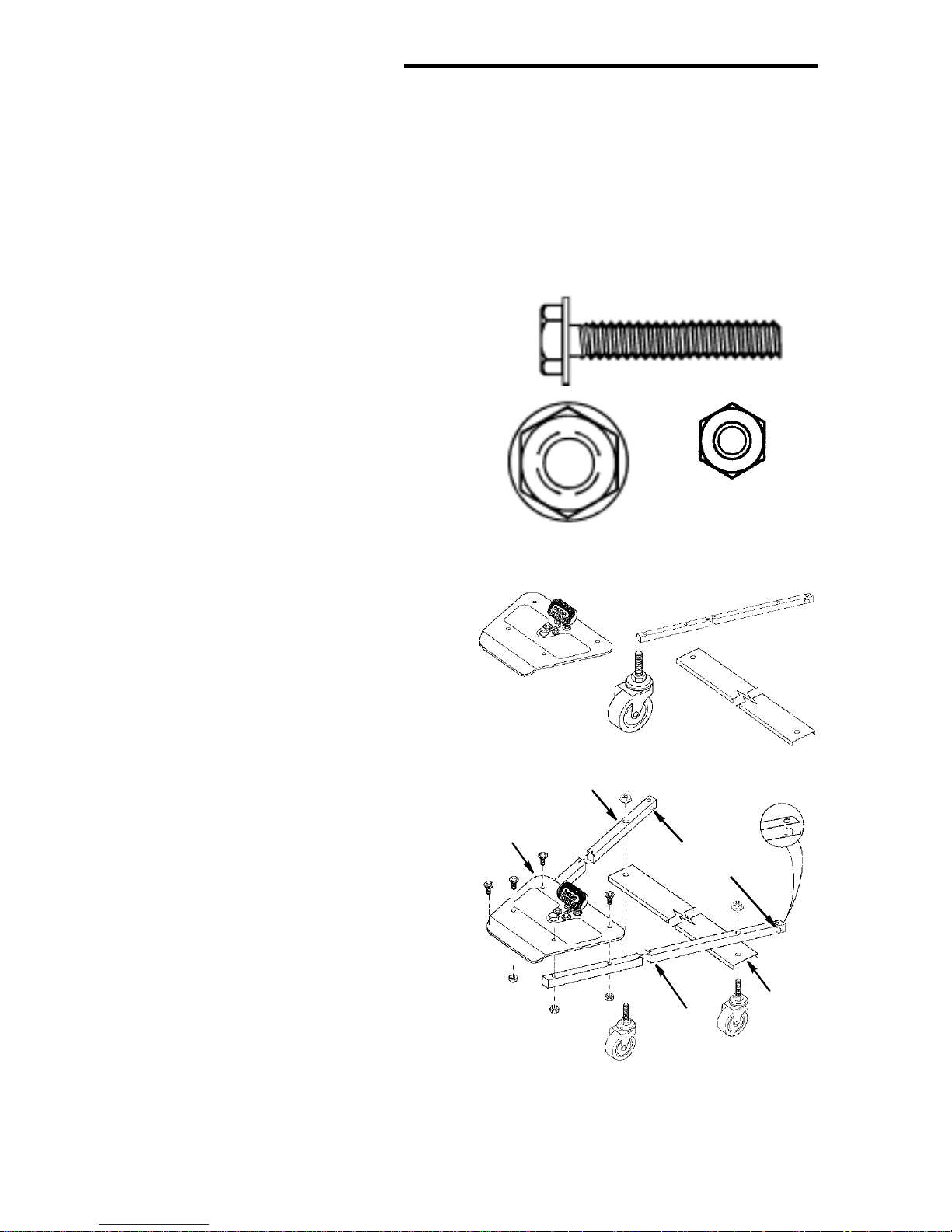
1.From bag of loose par ts remove the following hardware:
*4Hex Head Screw w/Washer, 1/4-20 x
1-1/2
*2Hex Nuts w/Serrated Flange 7/16
*4Lock Nuts 1/4-20
*Items marked with asterisk (*) are
shown actual size.
2.From the loose par ts find the following :
1 Plate Ass e m bly
2 Tube Rear (27" Length)
1 Channel Rear
2Casters
3.Assemble T ube Rear (2 7 inc h leng th) to
each side of the Plate Assembly as
shown using fou r each 1/4-20 x 1-1/2
hex head screw and lock nut. Loosely
assemble at this time.
NOTE: The larger hole at the end of the
tube, opposite the plate assembly,
must face down.
4.Align r ear chann el wit h holes in the rear
tubes as shown. Assemble caster
through channel and tube as shown.
Fasten with 7/ 16 n ut as shown . Lo osely
assemble at this time.
7/16 Hex Nut
w/Serrated Washer
Plate Assembly
Tube Rear
Plate
Assembly
Caster
1/4-20
Lock Nut
Tube Rear
Channel Rear
Large Hole
Facing Dow n
Tube
Rear
Channel
Rear
26
 Loading...