

RIDGID TS2424 Owner's Manual

2:1(5·60$18$/
$VVHPEO\
2SHUDWLRQ
5HSDLU3DUWV
)RU<RXU6DIHW\
5HDGDOOLQVWUXFWLRQVFDUHIXOO\
48(67,21625&200(176"
&$//5,'*,'
Part No. SP6127 Printed in U.S.A.
,1&+&2175$&725
6(5,(6%(/ 7'5,9(6$:
76

2
Table of Contents
Section Page
Safety Instructions For Table Saw .................................3
Safety Signal Words ...................................................3
Before Using The Saw ................................................3
When Installing Or Moving The Saw ...........................3
Before Each Use .........................................................4
To Reduce the Risk of Injury From Jams, Slips Or
Thrown Pieces (Kickbacks Or Throwbacks) ..............4
Plan Ahead To Protect Your Eyes, Hands,
Face and Ears ...........................................................5
Whenever Sawblade Is Spinning ................................5
Additional Safety Instructions For: Rip Type Cuts ......6
Additional Safety Instructions For: Crosscuts .............6
Additional Safety Instructions For Caster System: ......6
Before Using the Caster System .................................6
Glossary of Terms for Woodworking .............................7
Motor Specifications and Electrical Requirements ........8
Power Supply and Motor Specifications .....................8
General Electrical Connections ...................................8
110-120 Volt, 60 Hz. Tool Information ........................8
Changing Motor Voltage .............................................9
Motor Thermal Overload Protector ...........................10
Wire Sizes .................................................................10
Unpacking and Checking Contents .............................11
Tools Needed .................. ...... ....... ...... ....... ...... ....... ...11
Unpacking ....................... .......................................... 11
List of Loose Parts ....................................................12
List of Loose Parts (Caster) ......................................13
Loose Parts ...............................................................13
Assembly .............. ....................................................... 13
Installing Handwheels .................. ...... ....... ...... ....... ...13
Assembling Leg Stand ..............................................14
Assembling Universal Caster System .........................15
Frame Assembly .......................... ...... ....... ...... ....... ...15
Swivel Caster Assembly .............. ...... ....... ...... ....... ...16
Assembling Universal Caster System To Saw ............18
Locating Parts ...........................................................18
Leveling Feet Adjustment .........................................19
Assembly .............. ....................................................... 20
Mounting Your Saw ............... ....... ...... ....... ...... ....... ...20
Assembling Table Extensions ...................................21
Checking Table Insert ...............................................22
Checking Heeling Adjustment or Parallelism of
Sawblade to Miter Gauge Groove ...........................23
Checking Blade Tilt, or Squareness of
Blade to Table .........................................................24
Checking Tilt Mechanism ..........................................25
Installing Front Rip Fence Guide Bar ........................26
Installing Rear Fence Guide Bar ...............................27
Adjusting Rip Fence Guide Bars ...............................28
Rip Fence Alignment Adjustment ..............................29
Rip Fence Lock Lever Adjustment ............................29
Section Page
Installing Blade Guard ..............................................30
Aligning Blade Guard ................................................31
Mounting the Motor ...................... ...... ....... ...... ....... ... 32
Installing Belt ............................................................32
Installing Belt Guard .................................................33
Mounting Switch and End Caps ................................34
Installing Guide Bar End Caps ..................................34
Securing Electrical Cords .........................................34
Getting to Know Your Table Saw ................................35
Safety Instructions for Basic Saw Operations .............39
Before Each Use .......................................................39
To Reduce the Risk of Injury From Jams, Slips Or
Thrown Pieces (Kickbacks Or Throwbacks) ............39
Plan Ahead To Protect Your Eyes, Hands,
Face and Ears......................................................... 40
Whenever Sawblade Is Spinning ..............................40
Work Feed Devices .....................................................41
Push Stick .................................................................41
Featherboard ............................................................ 41
Push Block ................................................................41
Auxiliary Fence .........................................................42
Basic Saw Operations .................................................43
Using the Miter Gauge ..............................................43
Additional Safety Instructions for Crosscutting .........43
Crosscutting .................... .......................................... 43
Repetitive Crosscutting .............................................44
Miter Crosscutting .....................................................45
Bevel Crosscutting ....................................................45
Compound Crosscutting ...........................................45
Using the Rip Fence .................................................46
Additional Safety Instructions for Rip Cuts ...............46
Ripping ............................ ...... ............. ............. .......... 46
Bevel Ripping Narrow Work ......................................48
Using Featherboards for Thru-Sawing ......................48
Using Featherboards for Non Thru-Sawing ..............49
Resawing ........................ .......................................... 49
Using Carbide Tipped Blades ...................................50
Dadoing ....................................................................50
Rabbeting .................................................................51
Ploughing and Molding .............................................51
Molding ..................................................................... 52
Adjustments ................ ............. ............. ....... ............. ...5 3
Miter Gauge ..............................................................53
Maintaining Your Table Saw .......................................54
Maintenance ............................................................. 54
Lubrication ................................................................ 54
RIDGID Recommends the Following Accessories ......55
Troubleshooting ................. ............. ............. ...... .......... 55
General ..................................................................... 55
Motor ............................... ............. ............. ............. ...56
Repair Parts ................................................................57

3
Safety Instructions For Table Saw
Safety is a combin ation of comm on sens e, staying a lert and knowing how your tab le saw wo rks. Read th is manual t o
understand this table saw.
Safety Signal Words
DANGER: means if the safety information is not followed
someone will be seriously injured or killed.
WARNING: means if the safety information is not followed
someone could be seriously injured or killed.
CAUTION: means if the safety informat ion is not followed
someone may be injured.
Before Using The Saw
WARNING: to reduce the risk of mistakes that
could cause serious, permanent injury, do not plug
the table saw in until the following steps have been
satisfactorily completed.
• Com pletely assemble and align s aw (See “Assembly”
section).
• Learn the use and function of the ON-OFF switch
blade guard, spreader, anti-kickback device, miter
gauge, rip fence, table insert, blade elevation and
blade tilt controls (See “Getting to Know Your Table
Saw” section).
• Review and understand all safety instructions and
operating procedures in this manual.
• Review the maintenance methods for this saw (See
“Maintaining Your Table Saw” section)).
• F ind and rea d all the war ning lab els found on the saw
(shown below).
When Installing Or Moving The Saw
Reduce the Risk of Dangerous Environment.
• Use the saw in a dry, indoor place protected from rain.
• Keep work area well lighted.
• Use recommended accessories. Consult the owner’s
manual for recommended accessories. The use of
improper accessories ma y cause risk of in jury to persons.
To reduce the risk of injury from unexpected saw
movement.
• Bolt or clamp the saw to firm level surface where there is
plenty of room to handle and properly support the workpiece (See “Assembly-Mounting Your Sa w” secti on) .
• Support the saw so the table is level and the saw does
not rock.
• When using a table extension longer than 12" attached
to any side of the saw, bolt the saw to a stationary surface or prop up the outer end of the extension from the
floor or bench top to keep the saw from tipping.
• Put the saw where neither operator nor bystanders
must stand in line with the sawblade.
• To reduce the risk of injury from ele ctrical shock, make
sure your fingers do not touch th e plug’s metal prongs
when plugging in or unplugging the saw.
• Never Stand On Tool. Serious injury could occur if the
tool tips or you acciden tally hit the cutting to ol. Do not
store anything above or near the tool where anyone
might stand on the tool to reach them.

4
Safety Instructions For Table Saw (continued)
Before Each Use
Inspect your saw.
• To reduce the risk of injury from accidental starting,
turn the switch off, unplug the saw, and remove the
switch key before raising or removing the guard,
changing the cutting tool, changing the setup, or
adjusting anything. Make sure switch is in OFF position
before plugging in.
• Check for alignment of moving par ts, binding of moving
parts, breaka ge of parts, saw stability, and any other
conditions that may affect the way the saw works.
• If any part is missing, bent or broken in any way, or any
electrical par t does not work pro perly, turn the saw off
and unplug the saw.
• Replace damaged or missing parts before using the
saw again.
• Use the sawblade guard, spreader and anti-kickback
pawls for any thru-sawing (whenever the blade comes
through the top of the wor kpiece). Make sure th e antikickback pawls work properly. Make sure the spreader
is in line with sawblade (See “Assembly-Aligning Blade
Guard” section).
• Rem ove adjusti ng keys and wrench es. Form a hab it o f
checking for and removing keys and adjusting
wrenches from table top before turning saw on.
• Ma ke sure all cl amps and lo cks are tight an d no par ts
have excessive play.
To Reduce the Risk of Injury From Jams, Slips Or Thro wn Pieces (Kickbac ks Or Throwbacks)
Inspect Your Blade.
• Choose the right blade or cutting accessory for the
material and the type of cutting you plan to do.
• Use The Right Tool. Don’t force tool or attachment to
do a job it was not designed for.
• Never use grinding wheels, abrasive cutoff wheels,
friction wheels (metal cutting blades) wire wheels or
buffing wheels. They can fly apart explosively.
• Cut only wood, wood like or plastic mater ials. Do not
cut metal.
• Choose and inspect your cutting tool carefully:
- To reduce the r isk of cutting tool failure and thrown
shrapnel (broken pieces of blade), use only 10” or
smaller blades or other cutting tools marked for
speeds of 5000 rpm or higher.
- Always use unbr oken, balanced blades designed t o
fit this saw’s 5/8 inch arbor.
- When thru-sawing (making cuts where the blade
comes through the wor kpiece top), always use a 10
inch diameter blade. This keeps the spreader closest
to the blade.
- Do not over tighten arbor nut. Us e arbor wren ch es to
“snug” it securely.
- Use only sharp blades with pro perly set teeth. Consult a professional blade sharpener when in doubt.
- Keep blades clean of gum and resin.
- Never use the saw without th e proper blade insert.
Inspect your work area.
• Keep work area clean.
• Cluttered areas and benches invite accidents. Floor
must not be slippery from wax or sawdust.
• To reduce the risk of burns or other fire damage, never
use the saw near flammable liquids, vapors or gases.
• To reduce the risk of injur y, don’t do l ayout, assembly,
or setup work on the table while blade is spi nning. It
could cut or throw anything hitting the blade.
Plan your work
• Us e the right tool. Don’ t force tool or attachment to do
a job it was not designed for.
Inspect your workpiece.
• Ma ke sure there are no nails or foreign objects in the
part of the workpiece to be cut.
• Wh en cut tin g irreg ular ly shape d wor kpieces, pl an your
work so it will not slip and pinch the blade:
• A pi ece of molding for example, must lie flat or be hel d
by a fixture or jig that will not let it twist, rock or slip
while being cut. Us e jigs or fixtures where ne eded to
prevent workpiece from shifting.
• Us e a different, better suited type of tool for work that
can’t be made stable.
Plan your cut.
• To reduce the risk of kickbacks and throwbacks - when
a part o r all of the wor k pi ece b ind s on the blade and is
thrown violently back toward the front of the saw:
-Never cut Freehand. Always use either a rip fence,
miter gauge or fixtur e t o po si tio n a nd gui de the wor k ,
so it won’t twist or bind on the blade and kick back.
- Make sure ther e’s no debris between the workpiece
and its supports.
• Use extra caution with large, very small or awkward
workpieces.
• Use extra supports (tables, saw horses, blocks, etc.)
for any workpieces large enough to tip when not held
down to the table top. Never use another person as a
substitute for a table extension, or as additional support for a workpiece that is longer or wider than the
basic saw table, or to help feed, support or pull the
workpiece.
• Never confine the piece being cut off, that is, the piece
not against the r ip fence, miter gauge or fixture. Never
hold it, clamp it, touch i t, or use l en gth s to ps agai ns t i t.
It must be free to move. If confined, it could get
wedged against the blade and cause a kickback or
throwback.
• Never cut more than one workpiece at a time.
• Never turn your table saw “ON” be fore clearing everything except the workpiece and related support
devices o ff the table.
5
Plan Ahead To Protect Your Eyes, Hands, Face and Ears
Dress for safety
• Do not wea r loose clothin g, gloves, neckties or jewelry
(rings, wrist watch es). They can get caught and draw
you into moving parts.
• Wear nonslip footwear.
• Tie back long hair.
• Roll long sleeves above the elbow .
• Noi se levels vary widel y. To reduce the risk of po ssible
hearing damage, wear ea r plugs or muffs when using
table saw for hours at a time.
• Any power saw can throw foreign objects into the eyes.
This can result in permanent eye damage. Always
wear safety goggles, not glasses complyi ng with ANS I
Z87.1 (or in Canada CSA Z94-3-M88) shown on package. Everyday eyeglasses have only impact resist ant
lenses. They are not safety glasses. Safety goggles
are available at many local retail stores. Glasses or
goggles not in compliance with ANSI or CSA could
seriously hurt you when they break.
• For dusty operations, wear a dust mask along with
safety goggles.
Plan the way you will push the workpiece through.
• Never pull the workpiece through. Start and finish
the cut from the front of the table saw.
• Never put your fingers or hands in the path of the
sawblade or other cutting tool.
• Never reach in back of the cutting tool with either
hand to hold down workpiece, supp ort the workpiec e,
remove wood scraps, or for any other reason.
• r educe the ris k of hand posi tions where a su dden slip
could cause fingers or hand to move into a sawblade
or other cutting tool.
• Don’t overreach. Alw ays keep good footing an d b alance.
• Pu sh the workpiece against the rota tion of the blade,
never f eed material into the cutting tool from the rear of
the saw.
• Al ways push the workpiec e all the way past the sawblade.
• As much as poss ible, keep your face and body to one
side of the sawblade, out of line with a possible kickback or throwback.
• Set the cutting tool as low as possible for the cut you’re
planning.
Reduce the Risk of Accidental Starting.
• Ma ke sure switch is “OFF” before plugging saw into a
power outlet.
Whenever Sawblade Is Spinning
WARNING: Don’t allow familiarity (gained from frequent use of your table saw) to cause a careless
mistake. Always remember that a carele ss f r action
of a second is enough to cause a severe injury.
• Before actually cutting with the saw, watch it while it
runs for a short while. If it makes an unfamiliar noise or
vibrates a lot, stop immediately. Turn the saw off.
Unplug the saw. Do not restart until finding and correcting the problem.
• Make sure the top of the arbor or cutting tool turns
toward the front of the saw.
Keep Children Away.
• Keep all visitors a safe distance from the table saw.
• Make sur e bystanders are clear of the table saw and
workpiece.
Don’t Force Tool.
• Let the blade reach full speed before cutting.
• It will do the job better and safer at its designed rate.
• Feed the workpiece into the saw only fast enough to let
the blade cut without bogging down or binding.
Before freeing jammed material.
• Turn switch “OFF”.
• Wait for all moving parts to stop.
• Unplug the saw.
• Che ck blade, spreader and fence for proper alignment
before starting again.
To reduce the risk of throwback of cut off pieces.
• Use the guard assembly.
To remove loose pieces beneath or trapped inside
the guard.
• Turn saw “OFF”.
•Remove switch key.
• Wait for blade to stop before lifting the guard.
Before Leaving The Saw.
• Turn the saw off.
• Wait for blade to stop spinning.
• Unplug the saw.
• Make workshop child-proof. Lock the shop. Disconnect
master switches. Remove the yellow switch key. Stor e
it away from children and others not qualified to use
the tool.

6
Safety Instructions For Table Saws (continued)
Additional Safety Instructions For:
Rip Type Cuts.
• Never use the miter gauge when ripping.
• Use a push stick whenever the fence is 2 or more
inches from the blade.
• When thru-sawing, use an auxiliary fence and push
block whenever the fence must be between 1/2 and 2
inches of the blade.
• Never thru-saw rip cuts narrower than 1/2 inch. (See
“Basic Saw Operations-Ripping and Bevel Ripping”
sections.)
• Never rip anything shorter than 10” long.
• When using a push stick or push block, the trailing end
of the board must be square. A push stick or block
against an uneven end could slip off or push the work
away from the fence.
• A Featherboard can help guide the workpiece. (see
”Basic Saw Operation-Using Featherboards for ThruSawing.” section)
• Always use featherboards for any non thru rip type cuts.
(See “Basic Saw Operatio ns - Using Featherboards for
Non-Thru Sawing” section)
Before Starting.
• To reduce the risk of kickbacks and slips into the blade,
make sure the rip fence is parallel to the sawblade.
• Before thru-sa wi ng, chec k the ant i-kic k ba c k pa wls. The
pawls must stop a kickback once it has started.
Replace or sharpen anti-kickback pawls when points
become dull. (See “Maintain ing Your Table Saw - AntiKickback Pawls” section.)
• Plastic and composition (like hardboard) materials may
be cut on your saw. However, since these are usually
quite hard and slippery, the anti-kickback pawls may
not stop a ki ckback. Therefore, be espe ci al ly car ef ul i n
your setup and cutting procedures.
While Thru-sawing.
• To reduce the risk of kickbacks and slips into the blade,
always push forward on the section of the workpiec e
between the sawblade and the rip fence. Never push
forward on the piece being cut off.
Additional Safety Instructions For:
Crosscut Type Cuts.
• Never use the rip fence when crosscutting.
• An auxiliary wood facing attac hed to the miter gauge
can help prevent workpiece twisting and throwbacks.
Attach it to the slots provided. Make the facing long
enough and big enough to suppor t your work. Make
sure, however, it will not interfere with the sawblade
guard.
Before Starting.
• Us e jigs or fixtur es to help hold any piece too smal l to
extend across the full length of the miter gauge face
during the cut. This lets you properly hold the miter
gauge and workpiece and helps keep your hands away
from the blade.
While Cutting
• To reduce the risk of blade contact, always hold the
miter gauge as shown in “Basic Saw Operations Using The Miter Gauge”.
Additional Safety Instructions For Caster System:
Before Using the Caster System
Read the following warning located on the center frame:
To reduce the risk of injury from unexpected tool
movement.
• C heck to make sure tool does not move pri or to use. If
tool moves, adjust all four leveler feet down to support
the tool.
• Put the tool on a firm level surface where there is plenty
of room to handle and pr o perly support the workpi ec e.
Featherboard
See “Work Feed Devices” section for
Material and Dimensions
7
Glossary of Terms for Woodworking
Anti-Kickback Pawls
Device which, when proper ly maintained, is de signed to
stop the workpiece from being thrown towards the front of
the saw at the operator during ripping operation.
Arbor
The shaft on which a cutting tool is mounted.
Bevel Cut
An angle cutting operation made thr ough the face of the
workpiece.
Compound Cut
A simultaneous bevel and miter crosscutting operation.
Crosscut
A cutting operation made across the width of the work piece.
Dado
A non thru cut which produc es a square sided notch or
trough in the workpiece.
Featherboard
A device which can help guide workpieces during rip type
operation.
Freehand
Performing a cu t without the use of fence (guide), miter
gauge, fixture, hold down or ot her proper device to prevent the workpiece from twisting during the cutting operation. Twisting of the workpiece can cause it to be thrown.
Gum
A sticky, sap based residue from wood products.
Heel
Misalignment of the sawblade such that the blade is not
parallel to the miter gauge groove.
Kerf
The amount of material removed by the blade in a
through cut or the slot produced by the blade in a no nthrough or partial cut.
Kickback
An uncontrolled grabbing and throwing o f the workpiece
back toward the front of the saw.
Leading End
The end of the workpiec e whic h, dur ing a r ip type op eration, is pushed into the cutting tool first.
Miter Cut
An angle cutting o peration made a cross the width o f the
workpiece.
Molding
A non through c ut wh ic h produces a special sh ape in the
workpiece used for joining or decoration.
Ploughing
Grooving with the grain the length of the workpiece, using
the fence. (A type of non-through cut)
Push Stick
A device used to feed the workpiece through the saw during narrow ripping type operations which he lps keep the
operator’s hands well away from the blade.
Push Block
A device used for ripping type operations too n arrow to
allow use of a push stick.
Rabbet
A notch in the edge of a workpiece. (A type of nonthrough cut)
Resin
A sticky, sap based substance that has hardened.
Revolutions Per Minute (RPM)
The number of turns co mpleted by a spinning object in
one minute.
Rip Cut
A cutting operation along the length of the workpiece.
Sawblade Path
The area of the workpiece or table top directly in line with
either the travel of the blade or the part of the workpiec e
which will be, or has been, cut by the blade.
Set
The distance that the tip of the sawblade tooth is bent ( or
set) outward from the face of the blade.
Throw-Back
Throwing of pieces in a manner similar to a kickback.
Thru-Sawing
Any cutting operation where the blade extends completely through the thickness of the workpiece.
Trailing End
The workpiece end last cut by the blade in a ripping operation.
Workpiece
The item on which the cutting operation is being performed. The surfaces of a workpiece are commonly
referred to as faces, ends, and edges.
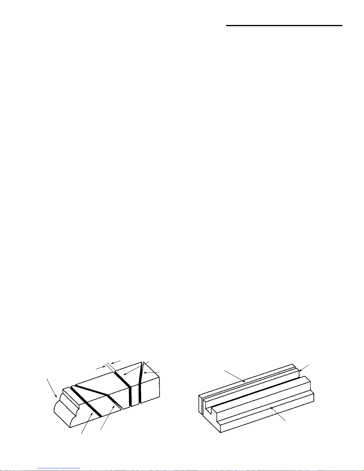
Molding
Kerf
Cross Cut
Miter Cut
Compound Cut
Bevel Cut
Rip Cut
Dado or
Rabbet
Ploughing
8
Motor Specifications and Electrical Requirements
Power Supply and Motor Specifications
WARNING: To reduce the risk of electrical hazards,
fire hazards or damage to the tool, use proper circuit protection. Your tool is wired at the factory for
operation using the voltage shown. Connect tool
to a power line with the appropriate voltage and a
15-amp branch circuit. Use a 15-amp time delay
type fuse or circuit breaker. To reduce the risk of
shock or fire, if power cord is worn or cut, or damaged in any way, have it replaced immediately.
The A-C motor used on this tool is a cap acit or sta rt, capacitor run non-reversible type, having the following specifications. It is wired at the factory for operatio n on 110- 120v A C,
60 Hz. service.
General Electrical Connections
DANGER: To reduce the risk of electrocution:
1. Use only identical replacement parts w hen servicing. Servicing should be performed by a
qualified service technician.
2. Do not use in rain or where floor is wet.
This tool is intended for indoor residential use
only.
WARNING: Do not permit fingers to touch the terminals of plug when installing or removing the
plug to or from the outlet.
110-120 Volt, 60 Hz. Tool Information
The plug supplied on your tool may not fit into the outlet
you are planning to use. You r local electrical code may
require slightly different power cord pl ug connections. If
these differences exist refer to and make the proper
adjustments per your local code before your tool is
plugged in and turned on.
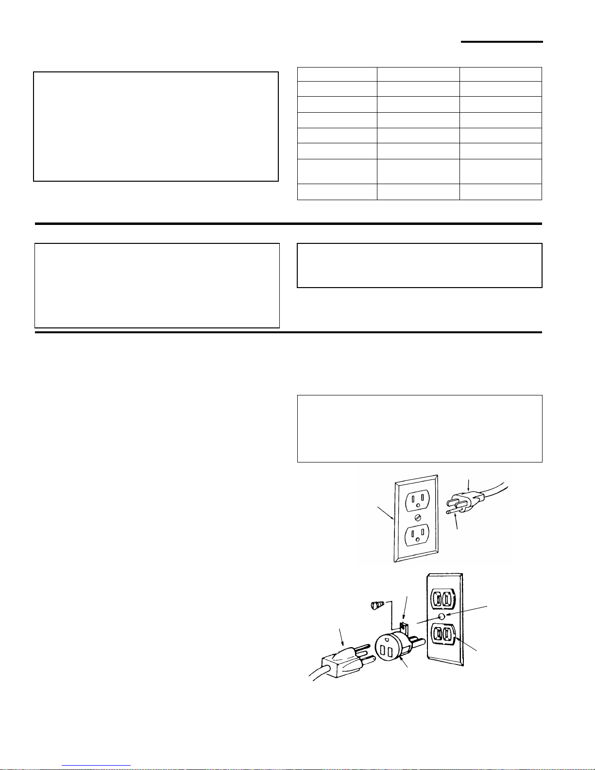
In the event of a malfunction or breakdown, grounding
provides a path of le ast resistance for electric curren t to
reduce the risk of electric shock. This tool is equipped
with an electric cord having an equipment-grounding conductor and a grounding plug, as shown. The plug must be
plugged into a mat ching outlet that is properly installed
and grounded in accordance with all local codes and
ordinances.
Do not modify the plug pr ovide d. I f it wi ll not fit the ou tle t ,
have the proper outlet installed by a qualified electrician.
A temporary ada pte r may be used to co nne ct t his pl ug t o
a 2-prong outlet as shown if a pro perly grounded three
prong outlet is not available. This temporary adapter
should be used only until a properly grounded three
prong outlet can be installed by a qualified electrician.
The green colored rigid ear, lug or the like, extending
from the adapter must be connected to a permanent
ground such as a properly grounded outlet box.
Improper connection of the equipment-grounding conductor can result in a r isk of electric s hock. The conductor with insulation having an outer surface that is green
with or without yellow stri pes i s the equ ipm ent-ground ing
conductor. If repair or replacem ent of the electr ic cord or
plug is necessary, do not connect the eq uip men t- groun ding conductor to a live terminal.
If the grounding instructions are not completely understood, or if you are in doubt as to whether the tool is properly grounded check with a qualified electrician or service
personnel.
WARNING: If not properly grounded, this tool can
cause an electrical shock, particularly when used
in damp locations, in proximity to plumbing, or out
of doors. If an electrical shock occurs there is the
potential of a secondary hazard, such as your
hands contacting the sawblade.
NOTE: The adapter illustrated is for use only if you
already have a properly grounded 2-prong outlet.
NOTE: In Canada the use of a temporar y adapter is not
permitted by the Canadian Electrical Code.
Wired for 120V Wired for 240V
Rated H.P
1-1/2 1-1/2
Voltage 110-120 220-240
Amperes 13 6.5
Hertz (Cycles) 60 50/60
Phase Single Single
RPM 3450 2875 (50 Hz)/
3450 (60 Hz)
Rotation of Shaft
Clockwise Clockwise
3-Prong
Adapter
2-Prong
Outlet
Make sure this
Is Connected
Ground
Plug
to a Known
Grounding Lug
Properly
Grounded
3-Prong Plug
Grounding
Prong
3-Prong Outlet
9
Changing Motor Voltage
WARNING: Electric shock can kill. To reduce the
risk of shock, never connect plug to power source
outlet until all assembly steps are completed.
Unplug saw before making or changing any connections.
NOTE: Power cord
lead connections for 110/120 volt and
220/240 volt applications are the same. This will show
how to change the interna l motor wiring to convert saw
from a 120V to a 240V application.
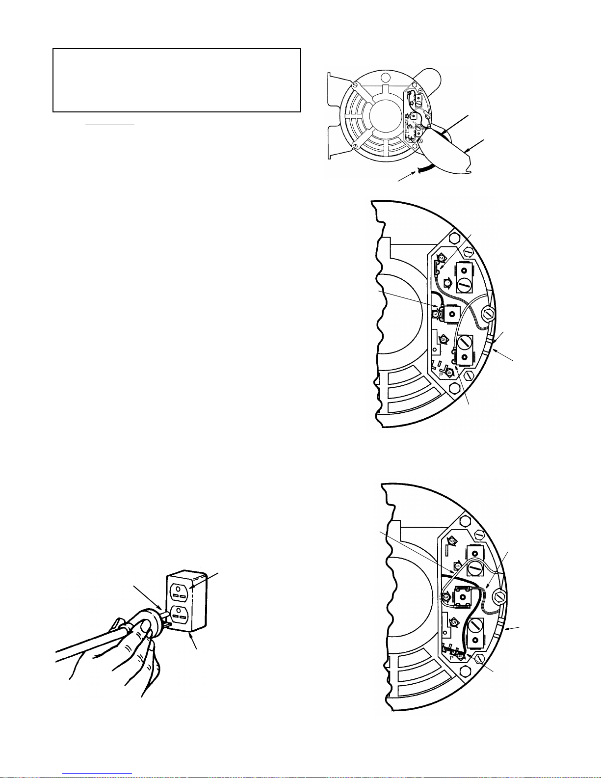
1. Open the motor connector box cover located on the
end of motor using a flat blade screwdriver to loosen
screws.
2. From the factory this motor is connected for 120V
usage. For 240V usage:
a. Remove the brown motor lead from termi nal #3 and
attach it to the “P” (parking position) plastic terminal.
NOTE: This brown lead is not require d for the 240
volt application and is “pa rked” in the pl astic “P” ter minal to keep it insulate d. Be sur e the b rown lead is
attached securely to the “P” terminal holder.
b. Remove the yellow motor lead from terminal #4 and
attach it to terminal #3.
c. Remove the red motor lead from terminal #2 and
attach it to terminal #3.
d. Cut off the 120 volt power cord plug and replace i t
with a (3 blade) 240 volt 15 amp U.L. listed plug.
(See illustration of 240V plug & receptacle.) Connect
the power cord white and black leads, respectively,
to the “hot” plug blade terminals and connect the
power cord green grounding wire to the plug ground
prong terminal.
3. Close motor conn ector box being sure that the power
cord is seated in the strain relief groove and tighten
box cover screws.
4. Plug your saw into a 220 -240V, 15amp, 3 blade recep-
tacle.
5. Make certain the receptacle is connected to a 240V
A.C. power supply through a 240V branch circuit having at least a 15 amp capacity and prote cted by a 15
amp time-delay fuse or circuit breaker.
Grounding
Prong
Grounded
Outlet Box
220-240V
15 Amp 3 Blade
Receptacle
Connector
Box Cover
Yellow Motor
Lead on
Terminal #3
220/240 Volt Connection
Brown Motor
Lead On
Termina l “P”
(Plastic)
Strain
Relief
Groove
Red Motor
Lead on
Terminal #3
Lead On
110/120 Volt Connection
Red Motor Lead
On Terminal #2
Brown Motor
Terminal #3
Yellow Motor Lead
On Terminal #4
Strain
Relief
Groove
Power Cord
To Switch Box
(As Received From Factory)
NOTE: Power
Cord Not
Shown For
Clarity
Cord Exit/
Cord Exit/
10
Motor Specifications and Electrical Requirements (continued)
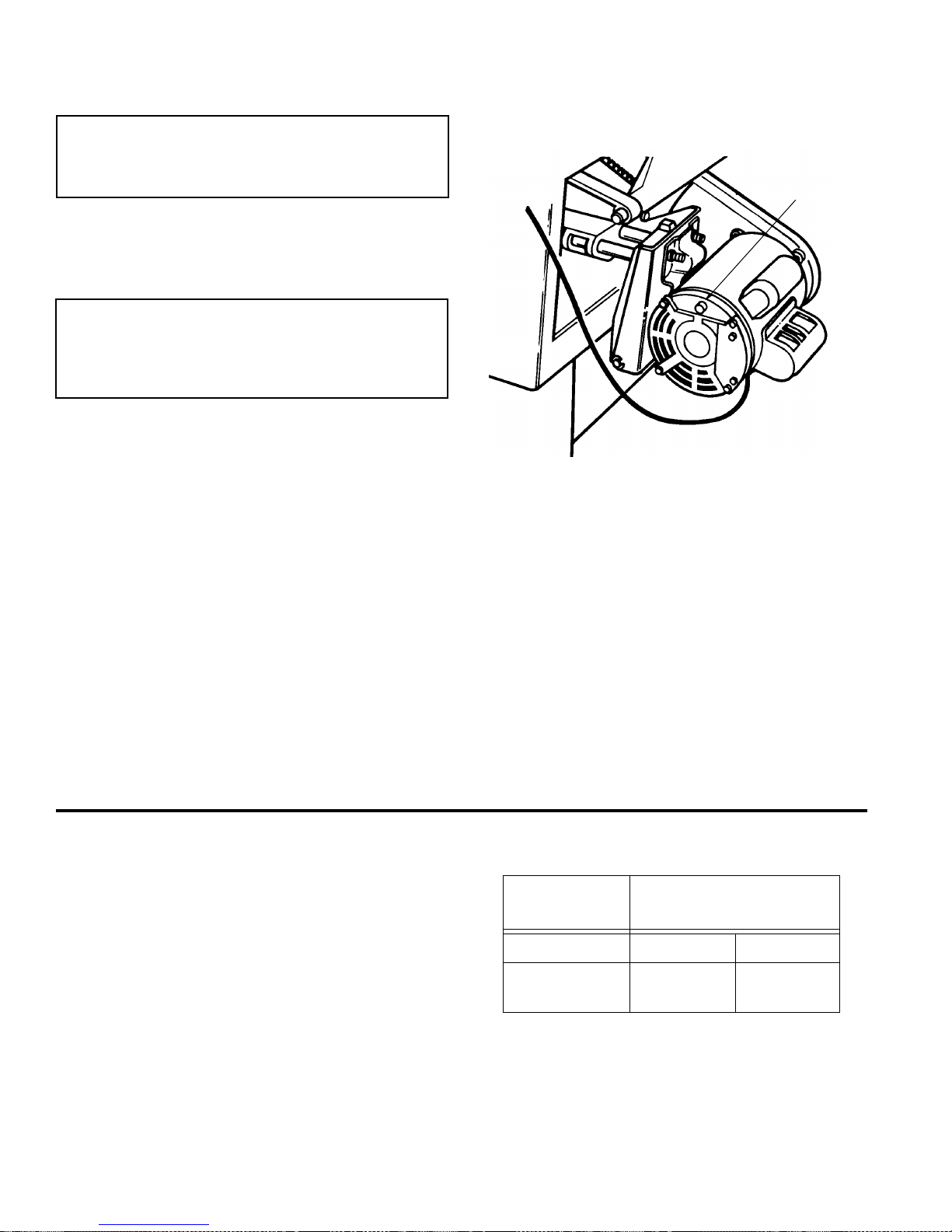
Motor Thermal Overload Protector
CAUTION: To reduce the risk of motor damage,
this motor should be blown out or vacuumed frequently to prevent sawdust buildup which will
interfere with normal motor ventilation.
Your saw is equipped with a manual-reset ther mal-overload protector designed to open the power line circuit
when the motor temperature exceeds a safe level, when
motor is overloaded or when a low voltage condition
exists.
WARNING: To reduce the risk of thrown objects or
blade contact from unexpected starting. If the protector stops the saw motor, immediately turn the
saw switch “OFF”, remove the key and allow motor
time to cool.
1. After cooling to a safe operating temperature, the overload protector can be res et by pushing the red button
on the end of the motor. If the red button will not click
into place immediately, the motor is still too hot and
must be allowed to cool for a while longer.
The time required for the motor to cool may be equal to
the length of time the saw was used before the thermal
overload protector opened. NOTE: An audible click will
indicate the protector is reset, push hard to hear the
click.
2. As soon as the red button is reset, the saw may be
started and operated normally.
3. Frequent “blowing” of fuses or tripping of circuit br eak-
ers may result if:
a. Motor is overloaded - Overloading can occur if you
feed too rapidly or if saw is misaligned.
b. Motor circuit i s fused differently from recomm enda-
tions - Always follow instructions for the proper fuse/
breaker. Do not use a fuse/breaker of greater capacity without consulting a qualified electrician.
c. Low voltage - Although the motor is designed for
operation on the voltage and frequency s pecif ied on
motor nameplate, normal loads will be handled
safely on voltage not more than 10% above or below
the nameplate voltage. Heavy loads, however,
require that voltage at motor terminals equals the
voltage specified on nameplate.
4. Most motor t roubles may be traced to loose or incorrect connections, overloading, reduced input voltage
(such as small size wire in the supply circuit) or to
overly long supply circuit wir e. Always check the connections, the load and the supply circuit whenever
motor fails to perform satisfactorily. Check wire sizes
and length with the Wire Size Chart below.
Wire Sizes
NOTE: Make sure the proper extension cord is used and
is in good condition.
The use of any extension cord will cause some loss of
power. To keep this to a minimum and to prevent overheating and motor burn-out, use the table shown to
determine the minimum wire size (A.W.G.) extension
cord.
Use only 3-wire extension cords which have 3-prong
grounding type plugs and 3-prong receptacles which
accept the tool’s plug.
Manual
Reset
Button
Extension
Cord Length
Gauge
(A.W.G.)
110-120V 220-240V
0-25 Ft.
26-50 Ft.
14
12
18
18
11
Unpacking and Checking Contents
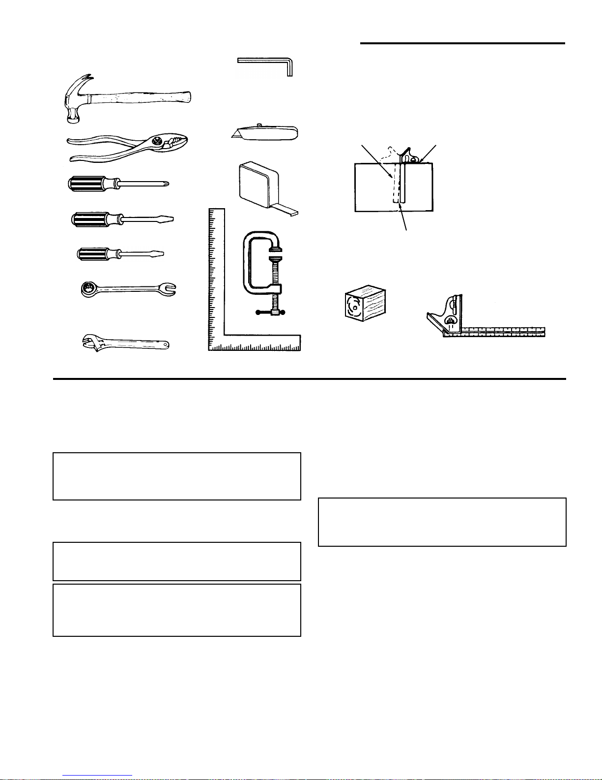
Tools Needed
Unpacking
1. Separate saw and all parts from packing materials and
check each one with the illustration and the “List of
Loose Parts” to make certain all it ems are accounted
for, before discarding any packing material.
WARNING: If any parts are missing, do not attempt
to assemble the table saw, plug in the power cord
or turn the switch on until the missing parts are
obtained and are installed correctly.
2. Remove the protective oil that is applied to the table
top and edges of the table and table extensions. Use
any ordinary household type grease and spot remover.
WARNING: To reduce the risk of fire or health hazard, never use gasoline, naptha, or similar highly
volatile solvents.
WARNING: The saw is heavy. To reduce the risk of
back injury, ge t help to lift the saw. Hold the saw
close to your body. Bend your knees so you can lift
with your legs, not your back .
3. Apply coat of pa ste wax to the table and table extensions.
NOTE: Before beginning assembly:
• Check that all parts are included. If you are missing any
part, do not assemble the saw. Contact your Authorized
Service Center to get the missing part.
• So metime s small parts can get los t in packaging ma terial. Do not throw away any packaging until saw is put
together. Check packaging for missing parts before
contacting RIDGID.
• A complet e par ts list (R epair Parts ) is at t he end of the
manual. Use this list to identify the par t number of the
missing part.
NOTE: At the beginning of each as sembly section it ems
such as nuts and bolts are shown actual size.
WARNING: For your own safety, never connect
plug to power source outlet until all assembly
steps are complete, and you have read and understand the safety and operating instructions.
Combination Square must be true. Ch eck it’s
accuracy as shown below.
Draw light line on
Should be no gap or overlap here when square
is flipped over in dotted position.
Phillips Screwdriver
Medium Screwdriver
Small Screwdriver
Hex “L” Wrenches
Pliers
Combination
Square
Tape Rule
3/32 In., 2.5mm,
Combination Wrenches
7/16 In. 1/2 In. 9/16 In.
board along edge
Utility Knife
C Clamp
Framing Square
Select the straight edge of
NOTE: The square and
straight edge are used to
3/4” thick board. This edge
must be perfectly straight.
align the saw. They must
be accurate if the saw is
to be aligned properly.
Hammer
Adjustable Wrench
4 x 4 Wood Block
1/8 In., 5/32 In., 3/16 In.
12
Unpacking and Checking Contents (continued)
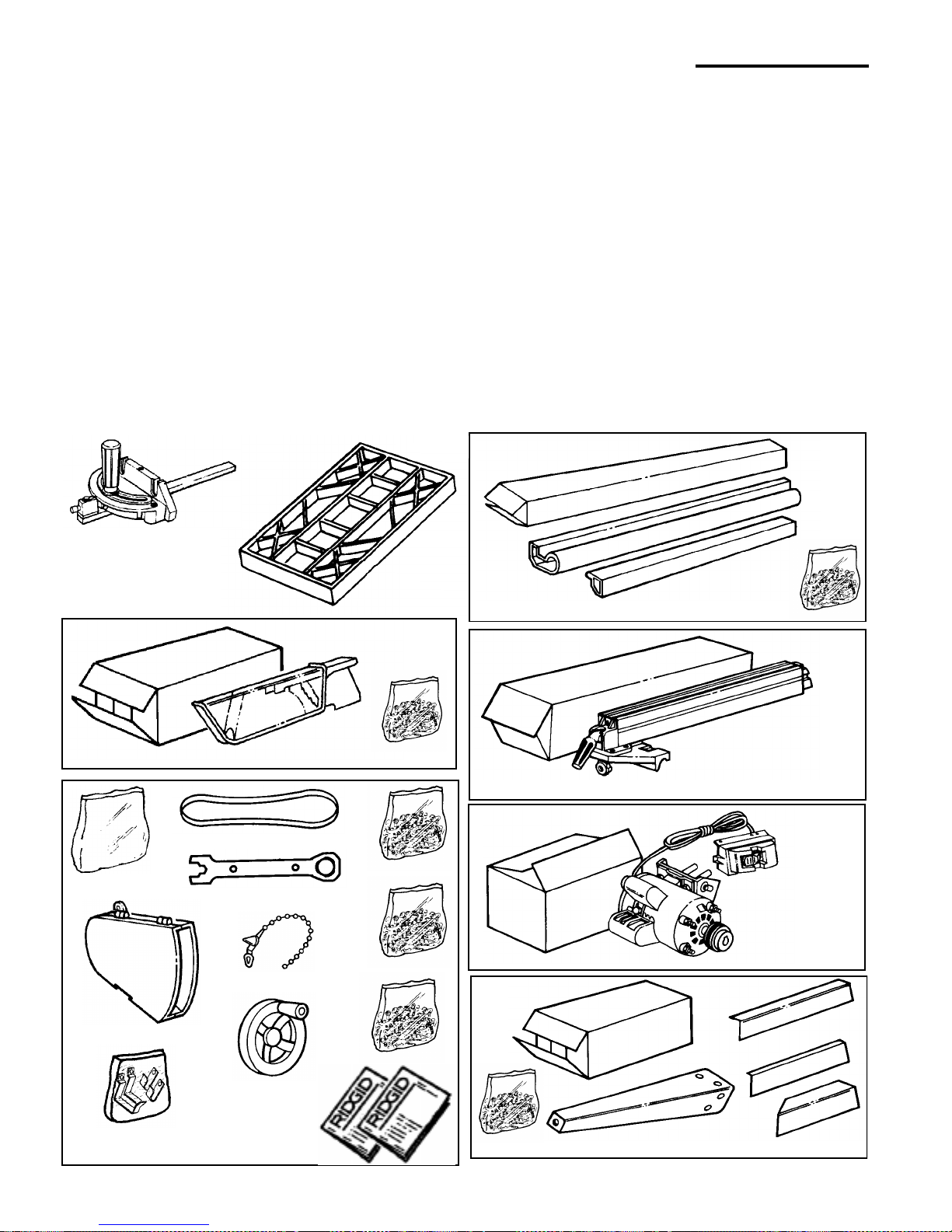
List of Loose Parts
Item Part Name Qty.
A Miter Gauge..........................................................1
B Table Extension ......................................... ....... ....2
Blade Guard Carton Containing:
C Blade Guard.........................................................1
D Blade Guard Parts Bag ........................................1
Large Parts Bag Containing:
E Belt Guard ............................................................1
F Storage Hook Bag................................................1
G Drive Belt..............................................................1
H Blade Wrench.......................................................1
J Wire Tie ................................................................2
K Handwheel ...........................................................2
L Trim Parts Bag......................................................1
M Table Extension Parts Bag ...................................1
N Miscel la neou s Parts Bag.............. ....... ...... ....... ....1
P Owners Manual (English) .....................................1
Q Owners Manual (Spanish)....................................1
Item Part Name Qty.
Fence Guide Bar Carton Containing:
R Front Fence Guide Bar.........................................1
S Rear Fence Guide Bar .............................. ....... .... 1
T Guide Bar Parts Bag ............................................1
Rip Fence Carton Containing:
U Rip Fence.............................................................1
Motor Carton Containing:
V Motor/Switch Assembly........................................1
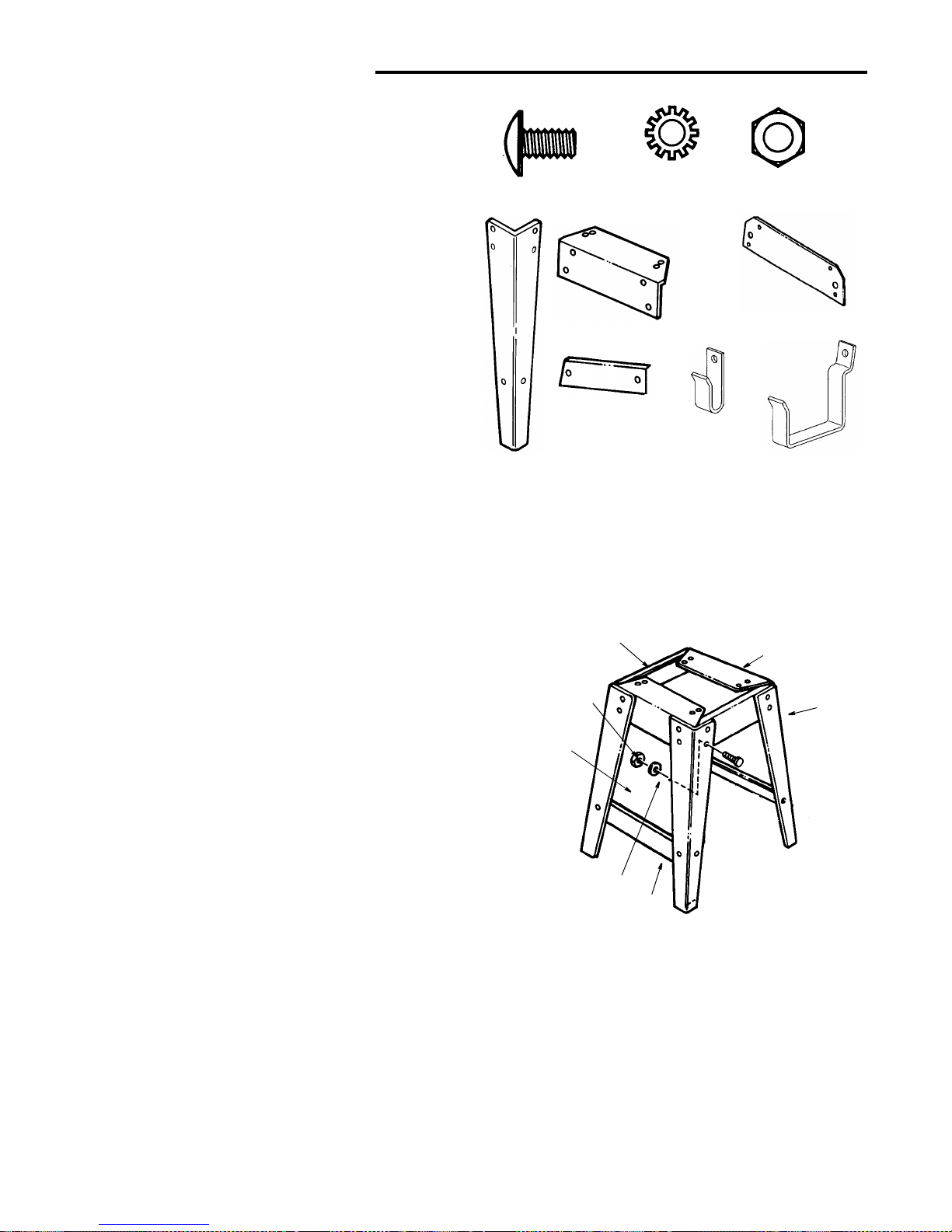
Leg Stand Carton Containing:
W Leg .......................................................................4
X Leg Brace (Short).................................................2
Y Side Stringer ........................................................2
Z End Stringer .........................................................2
AA Leg Stand Parts Bag ............................................1
Blade Guard Carton
Large Parts Bag
Motor Carton
Rip Fence Carton
Fence Guide Bar Carton (Service #509469)
T
U
V
W
X
Y
Z
D
C
E
S
Leg Stand Carton
A
B
F
G
J
P
L
M
N
H
Q
K
AA
R
13
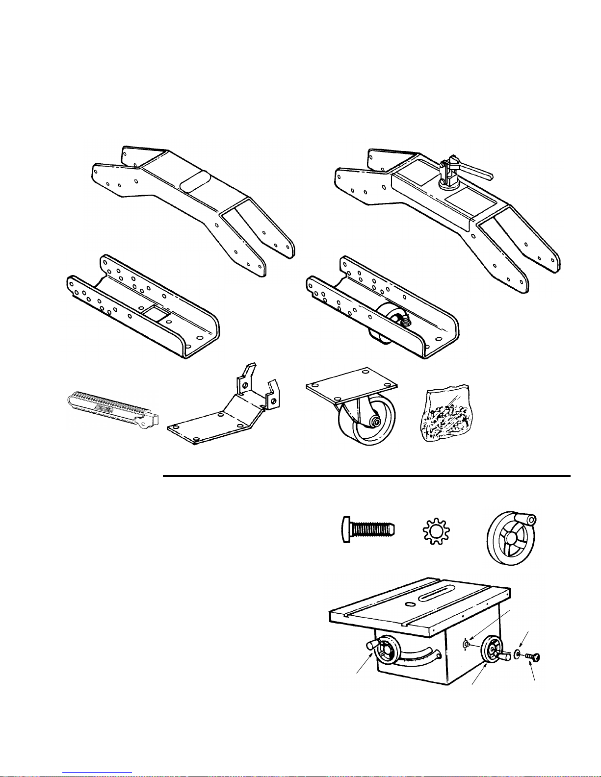
List of Loose Parts (Caster)
Item Description Qty.
A Center Frame ...................................................... 1
B Center Frame w/Actuator..................................... 1
C End Frame without Wheel.................................... 2
D End Frame with Fixed Wheel ............................... 2
Item Description Qty.
E Handle ..................................................................1
F Hin ge Plate ...................... ...... ...............................1
G Swivel Caster............ ....... ..................................... 1
H Bag Loose Parts Labeled "Caster" .......................1
Loose Parts
Assembly
Installing Handwheels
1. From the bag labeled “Miscel lan eou s” r em ove only the
following hardware:
2 Pan Head Screws, 10 - 32 x 5/8" long
2 Lockwashers, #10 External Type
From among the loose parts find the following:
2 Handwheels
2. Line up flat spots on shaft and handwheel, push
handwheel onto sh aft. Insta ll screw and lockwasher to
lock handwheel on shaft. Repeat for the other handwheel.
F
H
G
A
B
C
D
E
Pan Head Screw
10-32 x 5/8
#10 External
Lockwasher
Shaft
Pan Head
Bevel
Handwheel
Elevation
Handwheel
Lockwasher
Screw
Handwheel
14
Assembly (c ontinued)
Assembling Leg Stand
1. Locate the carton containing the leg stand.
Remove all parts from packing material.
2. From the bag labeled “Legs” remove the following
hardware:
20 Truss Head Screws, 1/4-20 x 1/2” long
20 Lockwashers, 1/4” External Type
20 Hex Nuts, 1/4-20
From leg stand carton find the following:
4 Legs
2 End Stringers
2 Side Stringers
2 Leg Braces
3. From among the loose parts find the following:
2 Miter Gauge Storage Hooks
2 Rip Fence Storage Hooks
4. See special instruction sheet for installing storage
hooks.
5. Assemble the legs as shown.
Insert the truss head screws thr ough the holes in the
legs, then through the holes in the side and end stringers.
Legs must be assembled on top of stringers
6. Install the lockwashers. Screw on the nuts hand tight.
7. Insert the truss head screws throug h the holes in the
legs, then through the holes in the leg braces.
8. Install the lockwashers. Sc rew on the nuts but do not
tighten until completely assembled.
1/4-20 x 1/2 In.
T
russ Head Screw
1/4 In. External
Lockwasher
1/4-20
Hex Nut
Leg
Stringers
End
Stringer
Side
Leg Brace
Miter Gauge
Storage Hooks
Rip Fence
Storage Hooks
Lockwasher
1/4-20
Hex Nut
Truss Head
Screw
Legs
End Stringers
Side Stringers
Leg Brace
Swivel Caster
Assembly Will Be
Installed Here
15
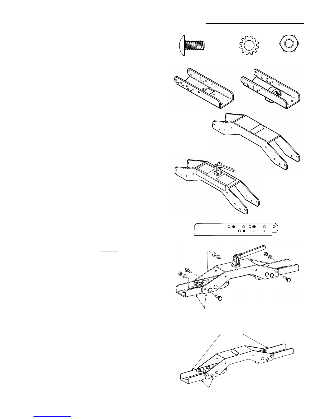
Frame Assembly
Locating Parts
1. From the bag labeled "C aster" re move only the following hardware:
24 Truss Head Screws, 1/4-20 x 1/2" Long
24 Lockwashers, 1/4" External Type
24 Hex Nuts, 1/4-20
2. From the caster carton find the following:
2 End Frames Without Wheel
2 End Frames With Wheel
1 Center Frame with Actuator
1 Center Frame
Setup
1. The end frame will be assem bled to the center frame
per the following instructions.
Use the holes shown with a “•” for your saw.
Assembly
1. Position the two end frames, without
wheels, inside the
center frame containing the swivel caster as shown.
Align holes in end frames (shown with a “•” for your
saw type) with the holes in the center frame. Fasten
each end frame, to the center frame using s ix 1/4-2 0 x
1/2 truss head screws, lockwashers, and nuts as
shown. The bottom of each end frame should be l evel
with the bottom of the center frame as illustrated.
Tighten all nuts with a 7/16" wrench.
2. Position the two end frames, with fixed wheels, inside
the center frame as shown. Align holes in end frames
(shown with a "•") with the holes in the center frame.
Fasten each end frame to the center frame using six
1/4-20 x 1/2 truss head screws, lockwashers, and
nuts as shown. The bottom of each end frame should
be level with the bottom of the center frame as illustrated.Tighten all nuts with a 7/16" wrench.
Level Bottom
With Edge
Level Bottom
With Edge
End Frames With
Wheels
Assembling Universal Caster System
Hex Nut
1/4-20
Trus s Hd. Sc r e w
1/4-20 x 1/2"
Lockwasher
Ext 1/4"
End Frame
Without Wheel
End Frame
With Wheel
Center Frame
Center Frame
w/Actuator
16
Assembling Universal Caster System (continued)
Swivel Caster Assembly
Locating Parts
1. From the bag labeled "Caster" remove the following
hardware:
4 Hex Head Bolts, 5/16-18 x 5/8" Long
4 Lockwashers, 5/16" External Type
5 Hex Nuts, 5/16-18
1 Hex Lock Nut 5/16-18
1 Button Head Bolt 5/16-18 x 1"
1 Hex Head Bolt 5/16-18 x 4-1/4
2. From the caster carton find the following:
1Swivel Caster
1 Hinge Plate
1 Center Frame w/Actuator
Assembly Instructions
1. Thread a 5/16-18 nut onto the 5/16-18 x 1 but ton h ead
cap screw all the way to the screw head. Then finger
tighten the cap screw into the actuator stem all the way
in. This will be adjusted later.
2. Mount the swivel caster wheel to the hi nge plate usin g
four 5/16-18 x 5/8 bolts, lock washers, and nuts as
shown. Tighten all nuts securely with 1/2" wren ch.
5/16-18
5/16-18 x 1
Button Head
Cap Screw
Actuator
Nut
5/16-18 Bolts
Lockwasher
Nuts
Hex Hd. Bolt
5/16-18 x 5/8
Hex Nut 5/16-18
Lockwasher 5/16
Hex Hd. Bolt
5/16-18 x 4-1/4
Hex Lock Nut 5/16-18
(Plastic Inner Ring)
Button Head Bolt
5/16-18 x 1
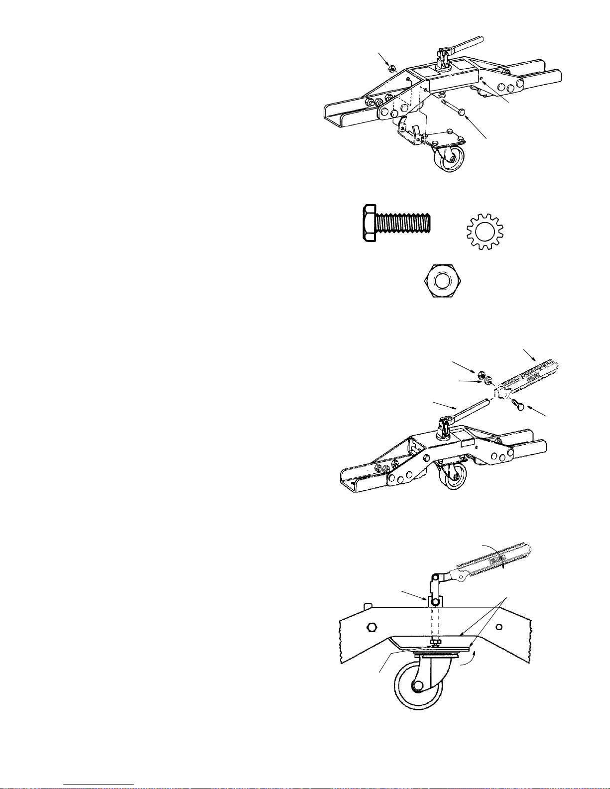
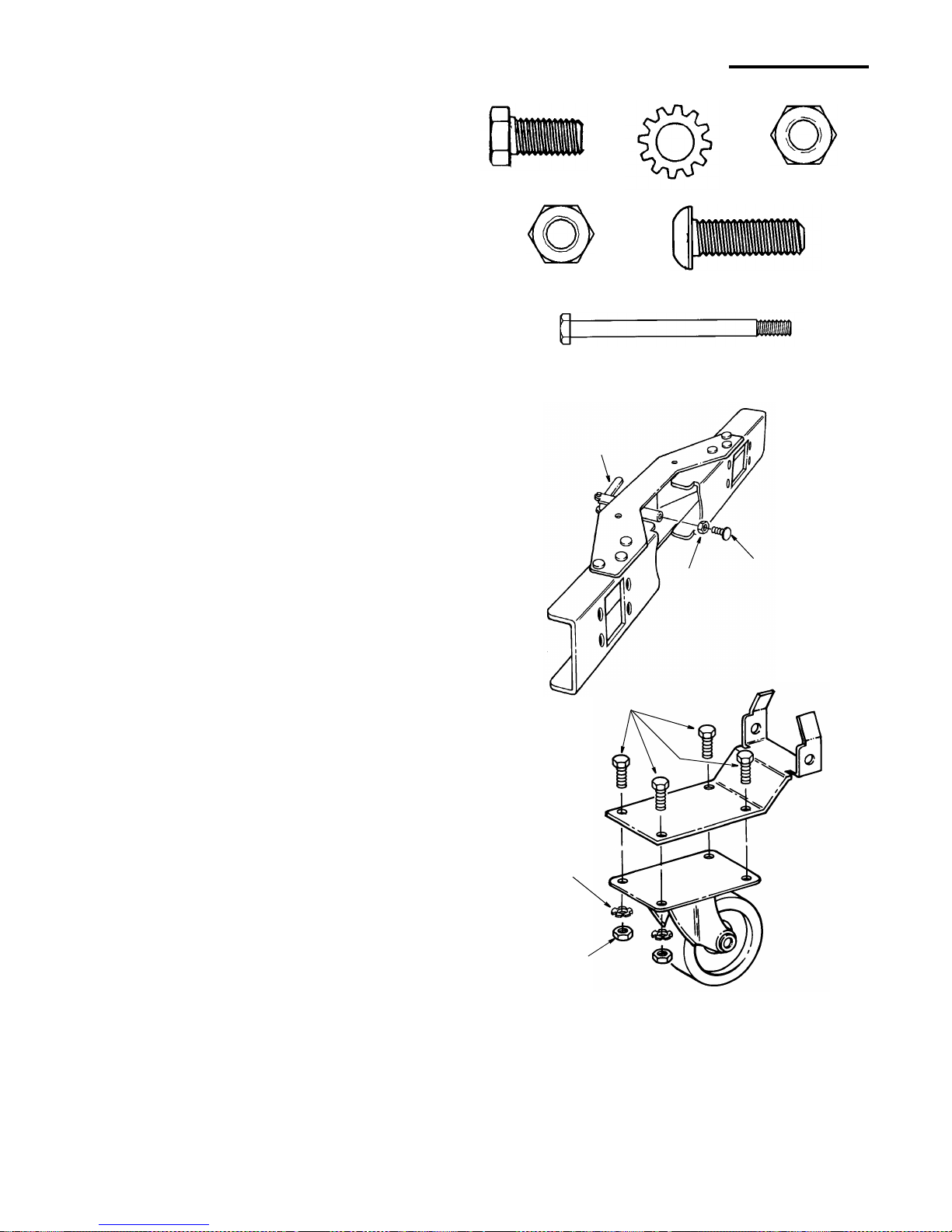
17
3. Hold the hinge plate with the caster in the center of the
frame as shown. Slide the 5/16-18 x 4- 1 /4 bo lt th ro ugh
frame and hinge plate. Finger tighten lock nut. Tighten
nut with a 1/2" and adjustable wrench but do not over
tighten. The hinge plate should fr eely pivot inside the
frame.
NOTE: The hinge plate can be mounted in either set of
holes as shown.
4. From the bag labeled "Caster" remove the following
hardware:
1 Hex Head Screw, 1/4-20 x 3/4" Long
1 Lockwasher, 1/4" External Type
1 Hex Nut, 1/4-20
5. From the caster carton find the following:
1 Handle
6. Slide handle all the way down, over actuator and fasten
using 1/4-20 x 3/4 hex head screw, lockw asher and nut
as shown. Tighten nut securely using a 7/16" and
adjustable wrench, compressing handle over stem.
Swivel Caster Adjustment
1. Rotate handle so that stem is fully extended inside
center frame. Using fingers adjust button head cap
screw so that the caster is aligned parallel with the bottom of the center frame as illustrated. Tighten nut
securely against stem.
NOTE: If actuator loosens, tighten using an adjustable
wrench on sides of actuator as shown.
5/16-18 x 4-1/4
Bolt
5/16-18
Lock Nut
Alternate
Mounting
Location
1/4-20
1/4-20 Nut
1/4 Lockwasher
Actuator
Handle
Screw
Rotate Handle Extending
Stem Inside Frame
Tighten Nut
Against
Caster Pivots
Up Inside
Frame When
Stem
Stem Is
Released
Align Edges
as Shown
Handle
Parallel
Tighten with
Adjustable Wrench
If Necessary
Hex Hd. Bolt
1/4-20 x 3/4"
Ext Lockwasher
1/4"
Hex Nut
1/4-20

18
Locating Parts
1. From the bag labeled "Caster" remove only the following hardware:
8 Hex Jam Nut, 3/8-16
4 3/8 Spring Lockwasher
8 Washer, 3/8 x 7/8 x 5/64
4 Foot Leveling
WARNING: If your saw has damaged or missing
parts, they must be repaired or replaced before
this assembly can be completed. Reference your
saw owner’s manual or Authorized Service Department if necessary.
Assembly Hints:
• The swivel caster m ay be mounted on the left or right
side of the leg stand. See illustration.
• Make sure the leg and stiffener bolts are loose in order
to align the holes in the le gs with the holes in the en d
frames.
• All four connections to your leg stand are done the
same way, using the same hardware.
• It may be hel pful to pla ce the frame o n blocks of wood
approximately 4" thick while assembling it to the leg
stand.
• Install frame assembly so warning label can be read
from outside the legs.
2. There are two holes in each end of the end frames.
Mount the casters throu gh the holes which will be to
the outside of your leg stand. Use leveling feet, nuts,
lockwashers and washers as shown.
Assembling Universal Caster System To Saw
Nut Hex Jam
3/8-16
Washer
3/8 x 7/8 x 5/64"
Lockwasher
Spring 3/8
Leveling Foot
Swivel Caster
Wood
Lockwasher
Nut
Washer
Leveling
Foot
Nut
Washer
Block
Use Holes
On Outside
19
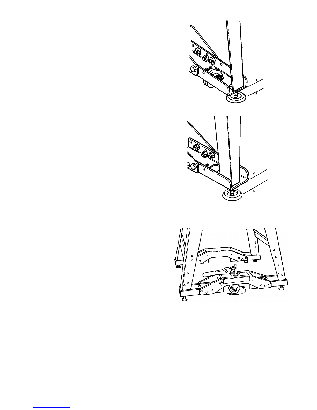
Leveling Feet Adjustment
1. Adjust fixed wheel cast er frame leveling feet so that
the saw is resting on two wheels. The leveling feet
should not touch the floor and should be adjusted
about 3/4" from the bottom of the end frame to the bottom of the foot as shown. Tighten all nuts us ing 9/16"
wrench.
2. Adjust the swivel caster frame leveling feet so that
the saw does not rock when the swivel caster is disengaged and the saw is resting on these two feet and the
two fixed wheels. The leveling feet should be approximately 1-3/4" from the bottom of the frame (on a level
floor surface) as shown. Make final adjustment to the
leveling feet to ensure that when the swivel caster is
disengaged, the caster ca n be rotated 360° by hand.
Tighten all nuts using 9/16" wrench.
Fixed Wheel
3/4"
Frame
Swivel Caster
1-3/4"
Frame
Rotate Caster
20
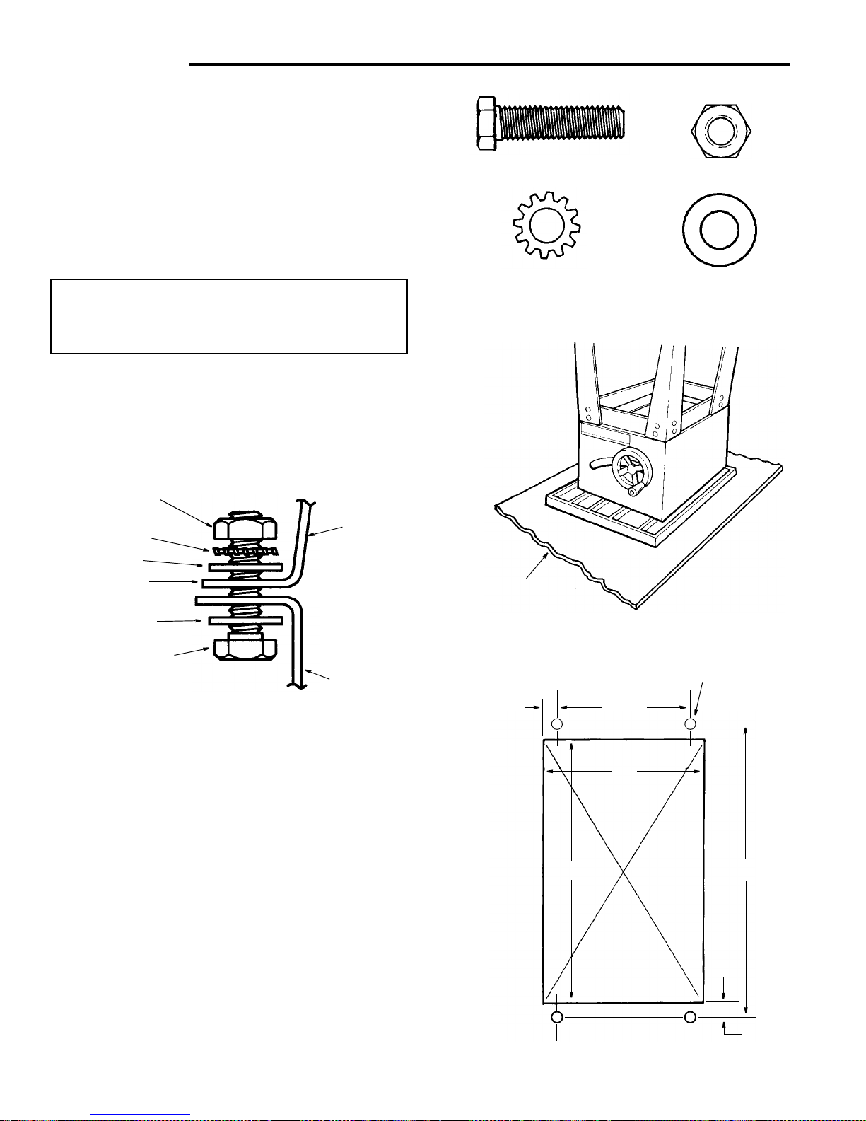
Mounting Your Saw
1. From the bag labeled “Legs” remove the following
hardware:
4 Hex Head Screws, 5/16-18 x 1-1/4" Long
4 Hex Nuts, 5/16-18
4 Lockw ashers, 5/16" External Type
8 Flat Washers, 11/32 x 11/16 x 1/16
2. Place the saw upside down onto a smooth piece of
cardboard or heavy paper, on the floor, so the saw is
resting on the table top.
WARNING: The saw is heavy. To reduce the risk of
back injury, get help to lift the saw. Hold the saw
close to your body. Bend your knees so you can lift
with your legs, not your back.
3. Place legs on saw so that holes in saw base and leg
set line up and trim label is facing front.
4. Install screw, washers, lockwasher and nut as shown.
5. Tighten all leg assembly and mounting hardware at
this time.
Bench Mounting
If you do not use the legset and mount the saw on a
bench, make sure that there i s an opening in the top of
the bench the same size as the openi ng in the bottom of
the saw so that the sawdust can drop through. Recommended working height is 33 to 37 inches from the top of
the saw table to the floor.
Hex Head Screw
Flat Washer
End Stiffener
Flat Washer
Lockwasher
Hex Nut
Saw Base
Leg Set
Assembl y
5/16-18 x 1-1/4 In
Hex Head Screw
5/16-18
Hex Nut
5/16 In External
Lockwasher
11/32 I.D.
Flat Washer
Cardboard
7/16 Dia.
11-1/4
13
15-3/4
16-3/4
1/2
Front of Saw
NOTE: All dimensions in inches
Opening
Mounting Holes
Bench
+
+
7/8
+
+
21
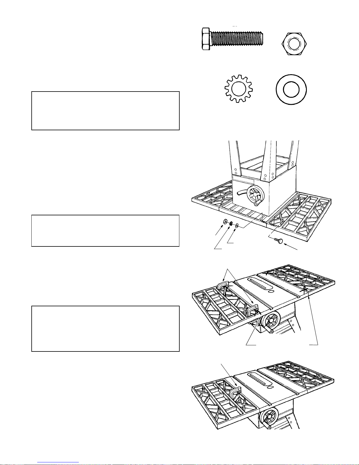
Assembling Table Extensions
1. From the bag labeled “Table Extensions” remove the
following hardware: (Quantity indicated is for two
extensions)
8 Hex Head Screws, 5/16-18 x 1-1/4" Long
8 Flat Washers, 11/32 x 11/16 x 1/16
8 Lockwashers, 5/16" External Type
8 Hex Nuts, 5/16-18
NOTE: Assemble with saw upside down.
WARNING: Stock table extensions must be
installed. They help support the fence guide bars.
An unsupported guide bar can twist. Twisted guide
bars can misalign fence. A misaligned fence can
cause binding or kickback. You could be hit or cut.
2. Insert four (4) 5/16-18 x 1 i n. long screws through the
holes in each extension.
3. Position extension against table so screws extend
through hole in table.
4. Install flat washers, lockwasher, and nuts on the
screws. With a 1/2" wrench, snug the four nuts just
enough to take the play out between the table and
extension. Do not tighten.
5. Repeat steps 1-4 to install the other extension.
6. Stand saw upright on legs. Roll saw over onto front
then up onto feet.
WARNING: The saw is heavy. To reduce the risk of
back injury, ge t help to lift the saw. Hold the saw
close to your body. Bend your knees so you can lift
with your legs, not your back .
7. Line up the front edge of extension with the front edge
of the table. At the spots marked “X” in the drawing,
tighten a “C” Clamp over the edge of table and extension. Use a combination square to check the alignment
of the front and top edges nearest the “X” ’s. Tighten
the two corner nuts only with a 1/2" wrench.
NOTE: This assembly may also be done without t he use
of a “C” Clamp.
WARNING: Table extensions must be installed.
Front edge of table and extensions must be lined
up. An uneven front edge can twist the fence guide
bar. Twisted guide bars can misalign fence. A misaligned fence can cause binding or kickback. You
could be hit or cut.
8. Tighten a “C” cla mp over the edge of table and extension at the center until th e extension is even with the
table surface as shown. Tighten the two center nuts
with a 1/2" wrench.
9. Repeat steps 7 and 8 to align the other extension.
5/16-18
Hex Nut
5/16 In External
Lockwasher
11/32 I.D.
Flat Washer
5/16-18 x 1-1/4 In
Hex Head Screw
Lockwasher
Flat Washer
Nut
Hex Screw
“C” Clamp
Align Front Edges
“C” Clamps
 Loading...