

Page 1

Page 2

Table of Contents
Section Page
Table of Conte nts ........................................ 2
Safety Instructions For Table Saw ............. 3
Safety Signal Words .................................. 3
Before Using The Saw ........ ... .... ................ 3
When Installing Or Moving The Saw ............ 4
Before Each Use ...........................................4
To Reduce the Risk of Injury From Jams, Slips
Or Thrown Pieces (Kickbacks Or
Throwba cks) .......... ............... ................ ....5
Plan Ahead To Protect Your Eyes, Hands,
Face and Ears ............................................6
Whenever Sawblade Is Spinning .................7
Additional Safety Instructions For: Rip Cuts.. 8
Additional Safety Instructions For: Crosscuts 9
Glossary of Terms for Woodworking ........ 9
Motor Specifications and Electrical
Requirem en ts ... .... ............ ... .... .... .... ...... 11
Power Supply and Motor Specifications ..11
General Electrical Connections ...............11
Motor Specifications and Electrical
Requirem en ts ... .... ............ ... .... .... .... ...... 12
Thermal O ver lo ad Prote ct or .......... .... .... .. 13
Wire Sizes ................................................ 13
Unpacking and Checking Contents ......... 14
Unpacki ng ..... ........... ............ ........... .......... 14
List of Loose Parts .................................... 14
Getting to Know Your Table Saw ............. 15
Alignme nt ........... ........... ........... ........ .......... 20
Tools Needed ........................................... 20
Remove Foam Motor Support .................. 20
Checking Table Insert ...............................20
Checking Heeling Adjustment or Parallelism
of Sawblade to Miter Gauge Groove ......21
Checking Blade Tilt, or Squarene ss of Blade
to Table .................................................. 23
To Check For Squareness, 90° Position ... 23
Adjustin g Rip Fence G uid e Bars . .... .... .... .. 25
Aligning Sliding Table Extension ..............26
Rip Fence Alignment Adjustment ............. 26
Rip Fence Lock Lever Adjustment ............27
Adjustin g Rip Indica tor ......... ... .... .... .... ......27
Checking Sliding Table Extension ............ 28
Installing Blade Guard ..............................28
Aligning Blade Guard ................................ 29
Removing and Installing Sawblade ...........30
Miter Gauge Align m ent ............... .... .... .... .. 31
Adjustin g Bevel Loc k ... .... .... ... ..................32
Mounting Your Saw ...................................33
Mounting Table Saw to Wor k bench
or Legset ................................................ 33
Workbench Mounting Using Hardware .....33
Table Saw Mounting Procedures .............. 33
Mounting Table Saw to RIDGID Universal
Power Tool Legset #AC9910 .................. 34
Section Page
Workbench Mounting Using "C" Clamps ..34
Supporting Tabl e Saw with Sawho rs es .... 34
Safety Instructions for Basic Saw
Operations ............... ............ .... ... .... .... .... 35
Before Each Use .......................................35
To Reduce the Risk of Injury From Jams, Slips
Or Thrown Pieces (Kickbacks Or
Throwbacks ) ................... ................... ..... 35
Plan Ahead To Protect Your Eyes, Hands,
Face and Ears ..........................................36
Whenever Sawblade Is Spinning ................ 37
Work Feed Devices ................................... 38
Attaching Wood Face Board .....................39
Push Block ..... ...........................................39
Work Feed Devices ................................... 40
Auxiliary Fenc e ......... .... .... ........................ 40
Fence Facing ............................................41
Basic Saw Operations ....... ........................ 42
Using the Miter Gauge .............................. 42
Additional Safety Instructions for
Crosscutting ...........................................42
Crosscutti ng ....... ........... ............ ........... ..... 42
Repetitive Crosscutting .............................43
Miter Crosscutting .....................................44
Bevel Crosscutting .................................... 44
Compound Cros s cutti ng ........................... 44
Using the Rip Fence ................................. 45
Additional Safety Instructions for Rip Cuts 45
Ripping ....... ........ .... ....... ........ ....... ........ .... . 46
Bevel Ripping Narrow Work ......................47
Using Featherboards for Thru Sawing ......48
Using Featherboards for
Non-Thru Sawing.................................... 49
Resawing ... ................... ............... ............. 50
Using Carbide Tipped Blades ................... 50
Dadoing .................................................... 51
Rabbeting ................................................. 52
Ploughing and Molding .............................52
Molding ..................................................... 53
Maintaining Your Table Saw .....................54
Maintenance ............................................. 54
Adjusting Nylon Set Screw ....................... 54
Replacing Carbon Brushes ....................... 55
Lubrication ................................................ 55
RIDGID Recommends the Following
Accessories .......................................... 55
Troubleshooting ..... ...................... ............. 56
General .. ................... ................... ............. 56
Motor ...... ....................... .... .... .... ... ............. 57
Repair Parts ...............................................58
Notes .......................................................... 65
2
Page 3

Safety Instructions For Table Saw
Safety is a combination of common sense, staying alert and knowing how
your table saw works. Read this manual to understand this table saw.
Safety Signal Words
DANGER: means if the safety infor-
mation is not followed someone will
be seriously injured or killed.
WARNING: means if the safety information is not followed someone
Before Using The Saw
could be seriously injured or killed.
CAUTION: means if the safe ty infor-
mation is not followed someone ma y
be injured.
WARNING: Some dust created by
power sa ndin g, sa win g, g rin ding ,
drilling, and other construction
activities contains chemicals
known (to the State of California)
to cause cancer, birth defects or
other repr od uc ti v e harm. Some
examples of these chemicals are:
Lead from lead-based paints
• Crystalline silica from bricks
and cement and other masonry
products, and
• Arsenic and chromium from
chemically-treated lumber.
Yo ur risk from these exposures
varies, depending on how often
you do this type of work. To
reduce your exposure to these
chemicals: work in a well ventilated area, and work with
approved safety equipment,
such as those dust masks that
are specially designed to filter
out microscopic particles.
WARNING: To reduce the risk of
mistakes that could cause serious, perma nent injury, do not
plug the table saw in unt i l the fo llowing steps have been satisfactorily completed.
• Completely align and align saw
(See “Alignment” section).
• Learn the use and function of the
ON-OFF switch, blade guard,
spreader, anti-kickback device,
miter gauge, rip fence, table insert,
blade elevation and blade bevel lock
controls (See “Getting to Know Your
Table Saw” section).
• Review and understand all safety
instructions and operating procedures in this manual.
• Review the maintenance methods
for this saw (See “Maintaining Your
Table Saw” section)).
3
Page 4
Safety Instructions For Table Saw (continued)
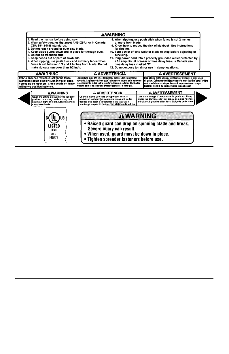
• Find and read all the warning labels found on the saw (shown below).
When Installing Or Moving The Saw
Reduce the Risk of Dangerous
Environment.
• Use the saw in a dry, indoor place
protected from rain.
• Keep work area well lighted.
• Use recom me nded acc essories.
Consult the owner’s manual for recommended accessories. The use of
improper accessories may cause
risk of injury to persons.
To reduce the risk of injury from
unexpected saw movement.
• Bolt or clamp the saw to firm level
surface where there is plenty of
room to handle and properly support
the workpiece (See “AssemblyMounting Your Saw” section).
• Support the saw so the table is level
and the saw does not rock.
• Put the saw where neither operator
nor bystanders must stand in line
with the sawblade.
• To reduce the risk of injury from
electrical shock, make sure your fingers do not touch the plug’s metal
prongs when plugging in or unplugging the saw.
• Never Stand On Tool. Serious
injury could occur if the tool tips or
you accidentally hit the cutting tool.
Do not store anything above or near
the tool where anyone might stand
on the tool to reach them.
Before Each Use
Inspect your saw.
• To reduce the risk of injury from
accidental starting, turn the switch
off, unplug the saw, and remove the
switch key before raising or removing the guard, changing the cutting
tool, changing the setup, or adjust-
ing anything. Make sure switch is in
OFF position before plugging in.
• Check for alignment of moving
parts, binding of moving parts,
breakage of parts, saw stability, and
any other conditions that may affect
the way the saw works.
4
Page 5

• If any part is missing, bent or broken
in any way, or any electrical part
does not work properly, t urn the saw
off and unplug the saw.
• Re place dam aged or missing parts
before using the saw again.
• Use the sawblade guard, sp reader
and anti-kickback pawls for any
thru-sawing (whenever the blade
comes through the top of the workpiece). Make sure the anti-kickback
pawls work properly. Make sure the
spreader is in line with sawblade
(See “Assembly-Aligning Blade
Guard” section).
• Remove adjusting keys and
wrenches. Form a habit of checking
for and removing keys and adjusting
wrenches from table top before turning saw on.
• Make sure all clamps and locks are
tight and no parts have excessive
play.
T o Reduce the Risk of Injury From Jams, Slips Or Thrown Pieces
(Kickbacks Or Throwbacks)
Inspect Your Blade.
• Ch oose the right blade or cutting
accessory for the material and the
type of cutting you plan to do.
• Use The Right Tool. Don’t force tool
or attachment to do a job it was not
designed for.
• Never use grinding wheels, abrasive
cutoff wheels, friction wheels (metal
cutting blades) wire wheels or buffing wheels. They can fly apart
explosively.
• Cu t only wood, wood like or plastic
materials. Do not cut metal.
• Choose and inspect your cutting
tool carefully:
- To reduce the risk of cutting tool
failure and thrown shrapnel (broken pieces of blade), use on ly 10”
or smaller blades or other cutting
tools marked for speeds of 5000
rpm or higher.
- Always use unbroken, balanced
blades designed to fit this saw’s 5/8
inch arbor.
- When thru-sawing (making cuts
where the blade comes through
the workpiece top), always use a
10 inch diameter blade. This keeps
the spreader closest to the blade.
- Do not over tighten arbor n ut. Use
arbor wrenches to “snug” it
securely.
- Use only sharp blades with properly set teeth. Consult a professional blade sharpener when in
doubt.
- Keep blades clean of gum and
resin.
- Never use the saw without the
proper blade insert.
Inspect your work area
• Keep work area clean.
• Cluttered areas and benches invite
accidents. Floor must not be slippery from wax or sawdust.
• To reduce the risk of burns or other
fire damage, never use the saw
near flammable liquids, vapors or
gases.
• To reduce the risk of injury, don’t do
layout, assembly, or setup work on
the table while blade is spinning. It
could cut or throw anything hitting
the blade.
5
Page 6

Safety Instructions For Table Saws (continued)
Plan your work
• Use the right tool. Don’t force tool or
attachment to do a job it was not
designed for.
Inspect your workpiece.
• Make s ure there are no nails or foreign objects in the part of the workpiece to be cut.
• W hen cutting irregularly shaped
workpieces, plan your work so it will
not slip and pinch the blade:
- A piece of molding for example,
must lie flat or be held by a fixture
or jig that will not let it twist, rock or
slip while being cut. Use jigs or fixtures where needed to prevent
workpiece from shifting.
• Use a different, better suited type of
tool for work that can’t be made stable.
Plan your cut
• To reduce the risk of kickbacks and
throwbacks - when a part or all of
the workpiece binds on the blade
and is thrown violently back toward
the front of the saw:
• Never cut Freehand. Always use
either a rip fence, miter gauge or fixture to position and guide the work,
so it won’t twist or bind on the blade
and kick back.
• Make sure there’s no debris
between the workpiece and its supports.
• Use extra caution with large, very
small or awkward workpieces.
• Use extra supports (tables, saw
horses, blocks, etc.) for any workpieces large enough to tip when not
held down to the table top. Never
use another person as a substitute
for a table extension, or as additional support for a workpiece that is
longer or wider than the basic saw
table, or to help f e ed, s upport or pull
the work piece.
• Never confine the piece being cut
off, that is, the piece not against the
rip fence, miter gauge or fixture.
Never hold it, clamp it, touch it, or
use length stops against it. It must
be free to move. If confined, it could
get wedged against the blade and
cause a kickback or throwback.
• Never cut more than one workpiece
at a time.
• Never turn your table saw “ON”
before clearing everything except
the workpiece and related support
devices off the table.
Plan Ahead To Protect Your Eyes, Hands, Face and Ears
Dress for safety
• Do not wear loose clothing, gloves,
neckties or jewelry (rings, wrist
watches). They can get caught and
draw you into moving parts.
• Wear nonslip footwear.
• Tie back long hair.
• Ro ll long sleeves above the elbow.
• Noise levels vary widely. To reduce
the risk of possible hearing damage,
wear ear plugs or muffs when using
table saw for hours at a time.
• Any power saw can throw foreign
objects into the eyes. This can result
in permanent eye damage. Always
wear safety goggles, not glasses
complying with ANSI Z87.1 (or in
Canada CSA Z94.3-99) shown on
package. Everyday eyeglasses
have only impact resistant lenses.
They are not safety glasses. Safety
goggles are available at many local
6
Page 7
retail stores. Glasses or goggles not
in compliance with ANSI or CSA
could seriously hurt you when they
break.
• For dusty operations, wear a dust
mask along with safety goggles.
Plan the way you will push the
workpiece through.
• Never pull the workpiece through.
Start and finish the cut from the front
of the table saw.
• Ne ver pu t your fingers or hands
in the path of the sawblade or other
cutting tool.
• Ne ver reach in back of the cutting
tool with either hand to hold down
workpiece, support the workpiece,
remove wood scraps, or for any
other reason.
• Reduce the risk of hand positions
where a sudden slip could cause fingers or hand to move into a sawblade or other cutting tool.
• Don’t overreach. Always keep good
footing and balance.
• Push the workpiece against the
rotation of the blade, never feed
materia l into the cutt ing to ol from the
rear of the saw.
• Always push the workpiece all the
way past the sawblade.
• As much as possible, keep your
face and body to one side of the
sawblade, out of line with a possible
kickback or thr o w b ack.
• Set the cutting tool as low as possible for the cut you’re planning.
Reduce the Risk of Accidental
Starting
• Make sure switch is “OFF” before
plugging saw into a power outlet.
Whenever Sawblade Is Spinning
WARNING: Do n't al low famil iarity
(gained f rom f requent use of
your table saw) to cause a careless mistake. Always remember
that a careless fraction of a second is enough to cause a severe
injury.
• Before actually cutting with the saw,
watch it while it runs for a short
while. If it makes an unfamiliar noise
or vibrates a lot, stop immediately .
Turn the saw off. Unplug the saw.
Do not restart until finding and correcting the problem.
• Make s ure the top of the arbor or
cutting tool turns toward the front of
the saw.
Keep Children Aw ay.
• Keep all visitors a safe distance
from the table saw.
• Make sure bystanders are clear of
the table saw and workpiece.
Don’t Forc e Tool.
• Let the blade reach full speed
before cutting.
• It will do the job better and safer at
its designed rate.
• Feed the workpiece into the saw
only fast enough to let the blade cut
without bogging down or binding.
Before freeing jammed material.
• Turn switch “OFF”.
• Wait for all moving parts to stop.
• Unplug the saw.
• Check blade, spreader and fence
for proper alignment before starting
again.
7
Page 8
Safety Instructions For Table Saws (continued)
To reduce the risk of throwback of
cut off pieces.
• Use the guard assembly.
To remove loose pieces beneath or
trappe d in sid e the guard.
• Turn saw “OFF”.
• Remove switch key.
• Wait for blade to stop before lifting
the guard.
Additional Safety Instructions For:
Rip Type Cuts.
• Never use the miter gauge when ripping. Store the miter gauge in the
area provided in the base.
• Use a push stick whenev er the
fence is 2 inches or more from the
blade.
• W hen thru-sawing, use an auxiliary
fence and push block whenever the
fence must be between 1/2 and 2
inches from the blade.
• Never thru-saw rip cuts narrower
than 1/2 inch. (See “Basic Saw
Operations-Ripping and Bevel Ripping” sections.)
• Never r ip any thi ng s hort er th an 10 ”
long.
• W hen using a push stick or push
block, the trailing end of the board
must be square. A push stick or
block against an uneven end could
slip off or push the work away from
the fence.
• A Featherbo ard can help guide the
workpiece. (see ”Basic Saw Operation-Using Featherboards for ThruSawing.” section)
• Alwa ys use featherboa rds for any
non thru rip type cuts. (See “Basic
Saw Operations - Using Featherboards for Non-Thru Sawing” section).
Before Leaving The Saw.
• Turn the saw off.
• Wait for blade to stop spinning.
• Unplug the saw.
• Make workshop child-proof. Lock
the shop. Disconnect master
switches. Remove the yel low switch
key. Store it away from children and
others not qualified to use the tool.
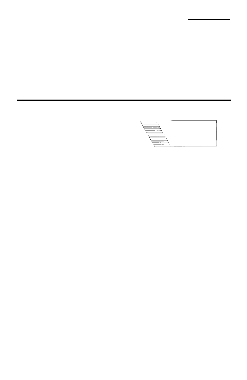
See “Work Feed Devices” section for
Featherboard
Material and Dimensions
Before Starting.
• To reduce the risk of kickbacks and
slips into the blade, make sure the
rip fence is parallel to the sawblade.
• Before thru-sawing, check the antikickback pawls . T h e pawl s m ust
stop a kickback once it has started.
Replace or sharpen anti-kickback
pawls when points become dull.
(See “Maintaining Your Table Saw Anti-Kickba ck Pa wls” section.)
• Plastic and composition (like hardboard) materials may be cut on your
saw. However, since these are usually quite hard and slippery, the antikickback pa wls may not stop a kickback. Therefore, be especially careful in your setup and cutting
procedures.
While Thru-sa w ing.
• To reduce the risk of kickbacks and
slips into the blade, always push forward on the section of the workpiece between the sawblade and
the rip fence. Never push forward on
the piece being cut off or directly in
line with the blade.
8
Page 9

Additional Safety Instructions For:
Crosscut T y pe Cuts .
• Ne ver use the rip fence when crosscutting.
• An auxiliary wood facing attached to
the miter gauge can help prevent
workpiece twisting and throwbacks.
Attach it to the slots provided. Make
the facing long enough and big
enough to support your work. Make
sure, however, it will not interfere
with the sawblade guard.
Before Starting
• Use jigs or fixtures to help hold any
piece too small to extend across the
full length of the miter gauge face
during the cut. This lets you properly
hold the miter gauge and workpiece
and helps keep your hands away
from the blade.
While Cutting
• To reduce the risk of blade contact,
always hold the miter gauge as
shown in “Basic Saw Operations Using The Miter Gauge”.
Glossary of Terms for Woodworking
Anti-Kickback Pawls
Device which, when properly maintained,
is designed to stop the work piece from
being thrown towards the front of the saw
at the operator during ripping operation.
Arbor
The shaft on which a cutti ng tool is
mounted.
Bevel Cut
An angle cutting operation made through
the face of the workpiece.
Compound Cut
A simultaneous bevel and miter crosscutting operation.
Crosscut
A cutting operation made acr oss the width
of the workpiece.
Dado
A non thru cut which produces a square
sided notch or trough in t he wo rkpiece.
Featherboard
A device which can help guide workpieces during rip typ e operation.
Freehand
Performing a cut without the use of fence
(guide), miter gauge, f ixtur e, hol d down or
other proper device to prevent the workpiece from twisting during the cutting
operation. Twisting of the workpiece can
cause it to be thrown.
Gum
A sticky, sap based residue from wood
products.
Heel
Misalignment of the sawblade such that
the blade i s not p ara llel t o the m iter gauge
groove.
Kerf
The amount of material removed by the
blade in a throug h cut or the slot produced
by the blade in a nonthrough or parti al cut.
Kickback
An uncontrolled grabbing and throwing of
the workpiec e back t oward the front of the
saw.
Leading End
The end of the workpiece which, during a
rip type operation, is pushed i nto the cutting tool first.
Miter Cut
An angle cutting operation made across
the width of the work piece.
Molding
A non through cut which produces a special shape in the workpiece used for joining or decor a t ion.
Ploughing
Grooving with the grain the length of the
workpiece, using the fence. (A type of
non-through cut.)
9
Page 10
Glossary of Terms for Woodworking (continued)
Push Stick
A device used to feed the workpiece
through the saw during narr ow ri pping
type operations which helps keep the
operator’s hands well away from the
blade.
Push Block
A device used for ripping type operations
too narrow to allow use of a push stick.
Rabbet
A notch in the edge of a workpiece. (A
type of non-through cut)
Resin
A sticky, sap based substance that has
hardened.
Revolutions Per Minute (RPM)
The number of turns complet ed by a spinning object in one minute.
Rip Cut
A cutting operati on along t he lengt h of the
workpiece.
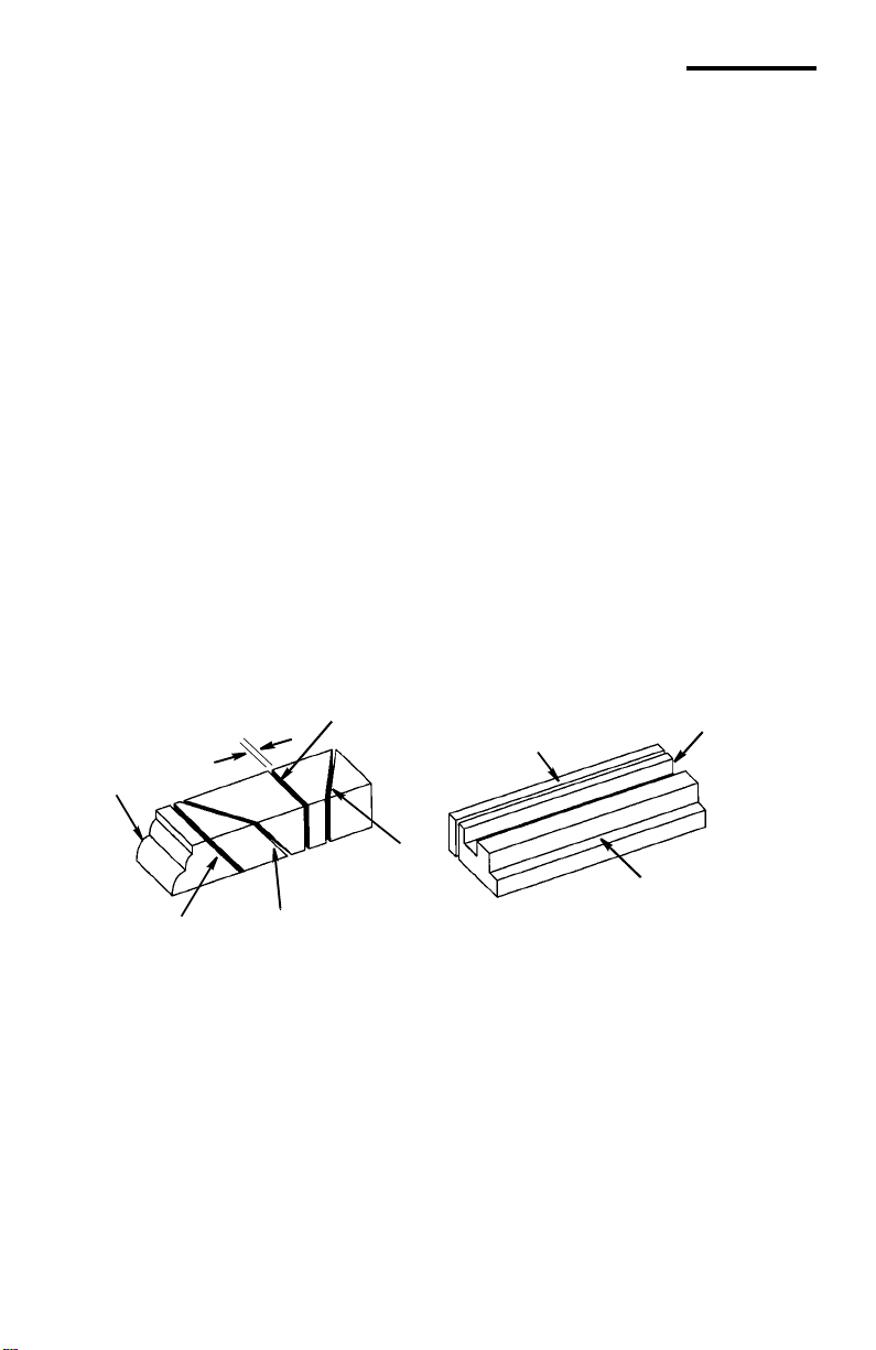
Sawblade Path
Cross Cut
Molding
Kerf
The area of the workpiece or table top
directly in line with either the travel of the
blade or the part of the workpiece which
will be, or has been, cut by the blade.
Set
The distance that the tip of the sawblade
tooth is bent (or set ) outward from the
face of the blade.
Throw-Back
Throwing of pieces in a manner similar to
a kickb ack.
Thru-Sawing
Any cutting oper ation where the blade
extends com pletely through the thickness
of the workpiece.
T railing End
The workpiec e end last cu t by t he bl ade in
a ripping operation.
Workpiece
The item on which the cutting operation is
being performed. The surfaces of a workpiece are commonly referred to as faces,
ends, and edges.
Rip Cut
Dado or
Ploughing
Bevel Cut
Miter Cut
Rabbet
Compound
Cut
10
Page 11

Motor Specificat ions and Electrical Requirements
Power Supply and Mot or
Specifications
WARNING: To reduce the risk of
electrical hazards, fire hazards or
damage to the tool, use proper
circuit pro te ct i on. Your tool is
wired at the factory for operation
using the voltage shown. Connect tool to a power line with the
appropriate voltage and a 15amp branch circuit. Use a 15amp time delay type fuse or circuit breaker. T o reduce the risk of
shock or fire, if power cord is
worn or cut, or da m aged in any
way, have it replaced immediately.
General Electrical Connections
The A-C motor used on this tool is a uni versal non-r eversible type, hav ing the following speci fi cations.
Voltage 120
Amperes 15
Hertz (C y cles) 60
Phase Single
RPM 4000
Rotation of Shaft Counterclockwise
(Blade E nd)
DANGER: To reduce the risk of
electrocution:
1. Use only identical replacement parts when servicing.
Servicing should be performed by a qualified service
technician.
2. Do not use in rain or where
floor is wet.
This tool is intended for
indoor residenti al use only.
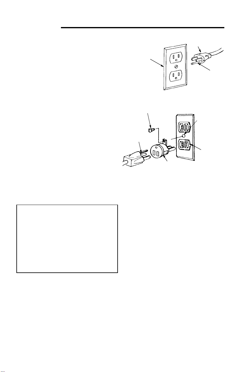
110-120 Volt, 60 Hz. Tool Information
The plug supplied on your tool may not fit
into the outlet you are planning to use.
Your local electrical code may require
slightly dif ferent power cord plug con nections. If these differences exist refer to
and make the proper adjust m ents per
your local code before your tool is
plugged in and turned on.
In the event of a malfuncti on or breakdown, grounding provides a path of least
resistance for electric current to reduce
WARNING: Do not permit fingers
to touch the terminals of plug
when installing or removing the
plug to or from the outlet.
the risk of electric shock. This tool is
equipped with an electric cord having an
equipment-grounding conductor and a
grounding pl ug, as shown. The plug must
be plugged into a matc hing outlet that is
properly in stalled and grounded i n a ccordance with all local codes and ordinances.
Do not modify the plug prov ide d. If it will
not fit the outl et, have the proper outlet
installed by a qual ified electrician.
11
Page 12
Motor Specificat ions and Electrical Requirements
(continued)
A temporary adapter may be used to connect this plug to a 2-pron g outl et as
shown if a properly grounded three prong
outlet is not available. This temporary
adapter should be used only until a properly grounded three prong outlet can be
installed by a qualified electrician. The
green colored rigid ear, lug or the like,
extending from the adapter must be connected to a permanent gro und such as a
properly grounded outlet box.
Improper connecti on of the equipmentgrounding conduct or can r esul t in a risk of
electric shock. The conductor with insulation having an outer sur face that is green
with or without yellow stripes is the equipment-grounding conductor. If repair or
replacement of the electric cord or plug is
necessary, do not connect the equipmentgrounding conductor to a live terminal.
If the grounding inst ructions are not completely understood, or if you are in doubt
as to whether the tool is properly
grounded check with a qual ified electrician or service personnel.
WARNING: If not properly
grounded, this tool can cause an
electrical shock, particularly
when used in damp locations, in
proximity to plumbing, or out of
doors. If an electrical shock
occurs there is the potential of a
secondary hazard, such as your
hands contacting the sawblade.
Properly
Grounded
3-Prong Outlet
Grounding Lug
3-Prong
Plug
Adapter
NOTE: The adapter illus trated is for use
only if you already have a properly
grounded 2-prong outlet.
NOTE: In Canada the use of a temporary
adapter is not permitted by the Canadian
Electrical Code.
3-Prong Plug
Grounding
Prong
Make sure this
Is Connected
to a Known
Ground
2-Prong
Outlet
12
Page 13
CAUTION: To reduce the risk of
motor damage, this motor
should be blown out or vacuumed frequently to prevent sawdust buildup which will interfere
with normal motor ventilation.
1.Frequent “blowing” of fuses or tripping
of circuit breakers may result if:
a. Motor is overloaded - Overloading
can occur if you feed too rapidly or if
saw blade is dull or misaligned.
b. Motor circuit is fused differently from
recommendations - Always follow
instructions for the proper fuse/
breaker. Do not use a fuse/br eaker of
greater capacity without consulting a
qualified el ectrician.
c. Low voltage - Although the motor is
designed for operation on the voltage
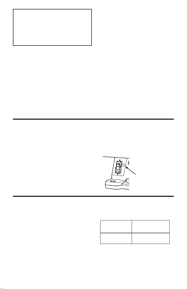
Thermal Overload Protec tor
This saw is equipped with a thermal overload device which will automatically “tri p”
and cause the saw to shut down if the
motor is overheating due to continuous
heavy cutting or stalling.
The overload device can only be reset
manually by the user after the motor has
been allowed to adequately cool. Allow
15-30 minutes.
Should the overload protector “trip”:
1.Tur n switch off and remove key.
2. Remove workpiece.
and frequency specified on motor
nameplate, normal loads will be handled safely on voltage not more than
10% above or below the nameplate
voltage. Heavy loads, however,
require that voltage at motor terminals equals the voltage specified on
nameplate.
2.Most motor troubles may be traced to
loose o r i nco r rec t conn ec t io ns , ov erl o ad ing, reduced inp ut voltage (such as
small size wire in the supply circuit or
extension cord) or to ov erly long supply
circuit wire or extension cord. Always
check the connections, the load and the
supply circuit whenever motor fails to
perf orm satisfactor ily. Check wire sizes
and length with the Wire Size Chart
below.
3.Wait 15-30 minutes.
4.Push in on the reset button.
5.If motor has cooled, button will remain
in.
Thermal Overload
Device
Wire Sizes
NOTE: Make sure the proper extension
cord is used and is in good condit ion.
The use of any extension cor d wil l cause
some loss of power. T o keep this to a minimum and to prevent overheating and
motor burn-out, use the t a ble shown to
determine the min imum wire size (A. W. G . )
extension cord.
Use only 3-wire extension cords which have
3-prong grounding type plugs and 3-prong
receptacles which accept the tool’s plug.
Extension
Cord Length
0-25 Ft.
26-50 Ft.
13
Gauge
(A.W.G.)
14
12
Page 14
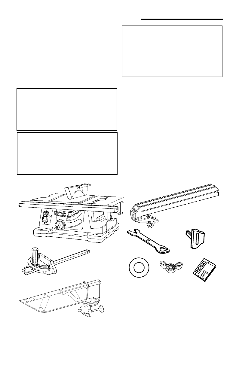
Unpacking and Checking Contents
Unpacking
Separate saw and all parts from packing
materials and check each one with the
illustrati on and the “List of Loose Parts ” to
make certain all items are accounted for,
before discarding any packing material.
Call 1-866-539-1710 or E-mail us at
info@ridgidwoodworking.com if any parts
are damaged or missing.
WARNING: If any parts are missing, do not attempt to use the
table saw, plug in the power cord
or turn the switch on until the
missing parts are obtained and
are installed correctly.
WARNING: The saw is heavy. To
reduce the risk of back injury,
hold the saw close to your body.
Bend your knees so you can lift
with your legs, not your back.
Use hand holds provided.
WARNING: For your own safety,
never connect plug to power
source outlet until all assembly
steps are complete, and you
have read and understand the
safety and operating instructions.
List of Loose Parts
Item Part Name Qty.
A Table Saw Assembly ....................... 1
B Miter Gauge.....................................1
C B lade Guard and Spreader..............1
D Rip Fence............ .. ............... .. ... ...... 1
E Arbor Wrenches .............................. 2
Item Part Name Qty.
F Sa fe ty Key........ ... .. ............... .. ... ...... 1
G Blade Storage Washers............ .......2
H Blade Storage Wingnut .......... .. ........1
J Operators Manual............................1
A
B
C
14
D
F
E
G
H
J
Page 15
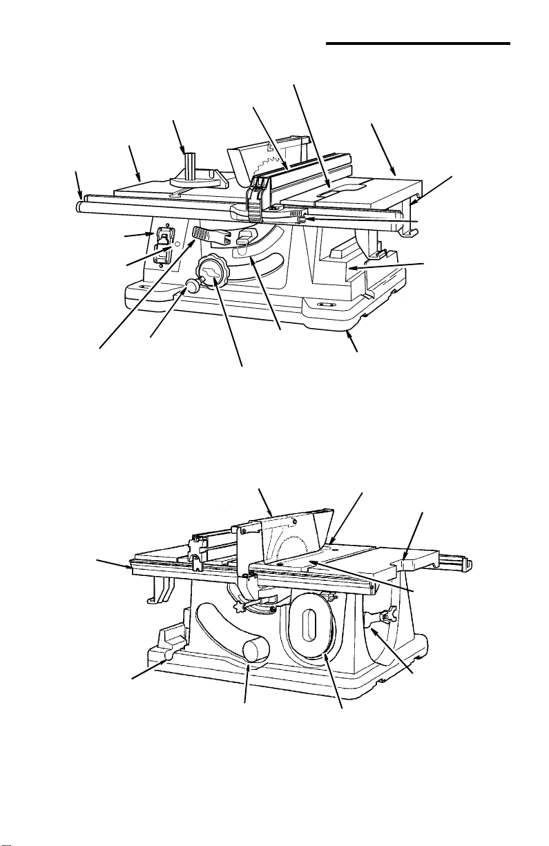
Getting to Know Your Table Saw
3 T able Extension
Lock Lever
1 Rip Fence
15 Miter Gauge
14 Table
Front Fence
Rail
4 Sliding Table
Extension
5 Rip Fence
Storage
12 On-Off
Switch
13 Thermal
Overload
Device
11 Blade Tilt
Lock Lever
Rear Fence
Rail
9 Elevation/Bevel
Handwheel
10 Blade Elevation
16 Blade Guard
Lock Knob
8 Blade Tilt
Scale
17 Ind-I-Cut
2 MicroAdjust
Rip Fence
6 MIter Gauge
Storage
7 Two-Piece
Base
18 Carry
Handles
19 Tabl e Insert
23 Blade Guard Stor ag e
for Non-thru Cuts
and Transportation Only
22 Sawdust
Ejection Port
15
20 Wrench & Blade
Storage
21 Cord Wrap
Page 16

Getting to Know Your Table Saw
1. Rip Fence...is locked in place by
pushing the l ock l ever d own u ntil the
lever rest s on the stop. To move the
fence, lift t he lock lever and grasp
the fence with one hand at the front.
“T” slot s are pr ovided i n the r ip fenc e
for attaching a wood fac ing when
using the dado head, or molding
head.
2. Micro-Adjust Rip Fence...allows
the operator to accurately adjust the
rip fence using only one hand. To
move the fence push in on the
micro-adjust knob and rotate.
3. Table Extension Lock
Lever...Locks the sliding table exten-
sion.
4. Sliding Table Extension
additional wor king surfa ce to support
large workpieces and increase rip
capability.
5. Rip Fence Storage...holds the
fence when not being used.
6. Miter Gauge Storage...holds the
miter gauge when not being used.
7. Two-Piece Base...supports table.
For additi onal stabili ty, holes are provided in base to bolt the saw to a
workbench or stand or sawhorses.
8. Blade Bevel Scale...shows the
degree the blade is beveled.
9. Elevation/Bevel Handwheel
a. Elevates or lowers the blade.
Turn the knob clockwise to elevate, counterclockwise to lowe r.
b. Use the knob to quickly tilt the
blade from 0° to 45°. Rotate the
outer hub for finer adj ustments.
When the blade is tilt ed to th e lef t
as far as it will go, it should be at
45° to the table and the bevel
...provides
pointer should point to 45°.
NOTE: There are limit stops
inside the saw which prevent the
blade from tilting beyond 45° to
the left and 0°. (See “ A djustments and Alignments” section
“Blade Bevel, or Squar eness of
Blade to Table”).
10. Blade Elevation Lock Knob...locks
the blade at the de sire d heig ht.
11.Blade Bevel Lock Lever...locks the
blade in the desired bevel position.
Lift the lever to the right to unlock
push to th e le ft to lock.
12. On-Off Switch
CAUTION: Before turning switch
“ON”, make sure the blade
guard is correctly installed and
operating pro perly.
The On-Off Switch has a locking fea-
ture. This feature is intended to help
prevent unauthorized and possible
hazardous use by child ren and others.
a. To turn saw ON, insert key, stand to
either side of the bl ade, never in line
with it, place finger under switch
lever and pull end of lever out.
After turning switch ON, always allow
the blade to come up to full speed
before cutting. Do not cycle the
motor switch on and off rapidly, as
this may cause the sawblade to
loosen. In the event this should ever
occur, allow the sawblade to come to
a complete stop and retighten the
arbor nut normally, not excessively.
Never leave the saw while the power
is ON.
16
Page 17
b. To turn saw OFF, PUSH lever in.
Never leave the saw until the cutting
tool has come to a complete stop.
c. To l ock switch in OFF position, hold
switch IN with one hand, REMOVE
key with other hand.
WARNING: For your own safety,
lower blade or other cuttin g tool
below table surface. (If blade is
tilted, return it to vertical, 90°,
position.) Always lock the
switch “OFF”. When saw is not
in use, remove key and keep it in
a safe place. Also, in the event
of a power failure (all of your
lights go out) turn switch off,
lock it and remove th e key. This
will prevent the saw from starting up again when the power
comes back on.
Key
Switch
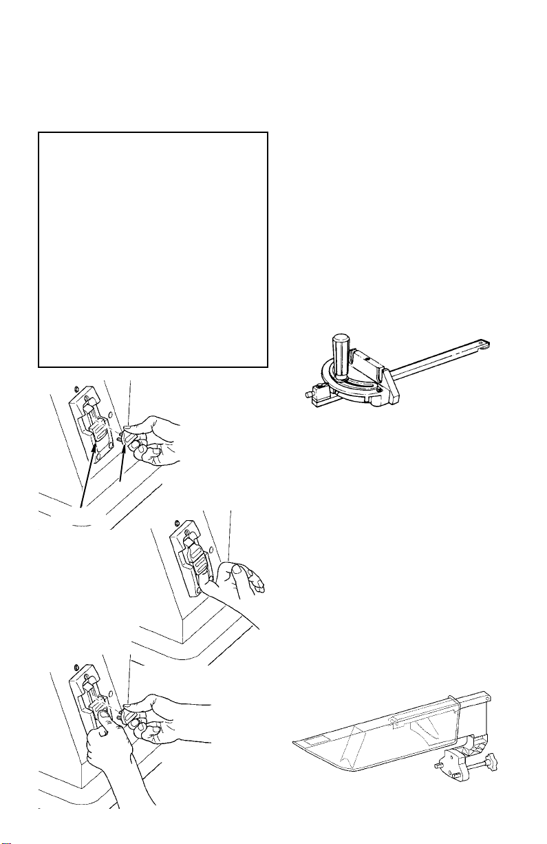
13. Thermal Overload Device...opens
the power line circuit when the motor
temperature exceeds a safe level,
when the motor is overloaded or
when a lower voltage condition exists.
It can be reset by pressing the reset
button after the motor returns to normal temperate.
14. Table...provides working surface to
support workpie ces.
15. Miter Gauge...head is locked in
position for cross cutting or mitering
by tightening the lock knob. Always
securely lock it when in use.
a. There are adjust able s crew sto ps
for the stop pin 0° and 45° right
and left posit ions f or c onven ientl y
setting the miter gauge to cut
miters at these standard angles.
16. Blade Guard
Use the sawblade guard, spreader
and ant i-kickback pawls for any thrusawing (whenever the blade comes
through the top of the workpiece).
Make sure the anti-kickback pawls
work properly. Make sure the
spreader is in line with sawblade.
(See “Aligning Blade Guard” se ction)
To remove the guard for special
operations, loosen the blade guard
locking knob. Do not dist urb the setting of the spreader brac ket.
When replacing the guar d, position
the two (2) locator pins on the blade
guard into the m atching holes in the
cradle. Securely ti ghten the blade
guard locking knob.
17
Page 18

Getting to Know Your Table Saw (continued)
17. Ind-I-Cut
The plastic disk em bedded in the
table in front of the sawblade, is provided for marking the locat ion of the
“sawcut” (kerf) on the workpiece.
Check disk location: If it is above
table surfa ce, place a piece of hardwood on top of it and tap it down
with a hammer.
18. Carry Handles...grasp the table
here when picking up t he saw.
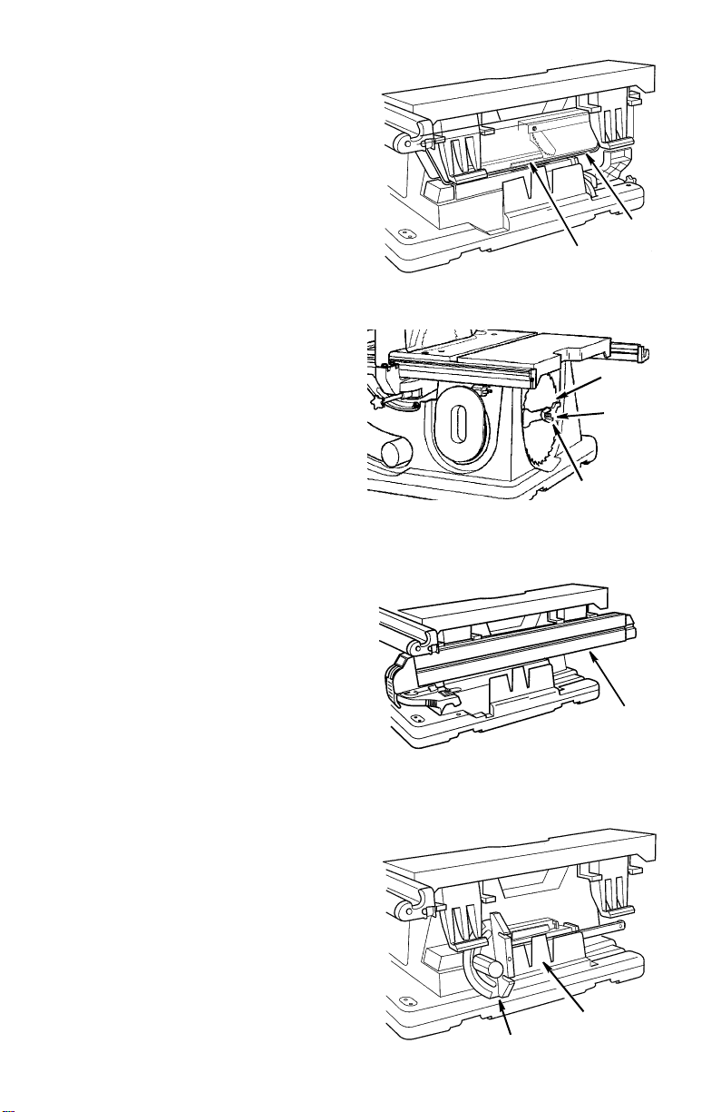
19. Table Insert
Is removable for removing or install-
ing blade or other cutting tools.
WARNING: For your own safety
turn switch "OFF" and remove
plug from power source before
removing insert.
To remove the insert.
a. Make sure saw is off and
unplugged.
b. Lower the blade below the table
surface.
c. Raise blade guard.
d. Loosen flat head screw.
e. Lift insert from front end, and pull
toward front of saw.
WARNING: To reduce the risk of
injury from a thrown wo rkpiece,
blade parts, or blade contact,
never operate saw without the
proper insert in place. Use the
sawblade insert when sawing.
Use the dado/molding head
insert when using a dado blade
or molding head.
20. Wrench/Blade Storag e.. .conve-
niently stores arbor wrenches as
well as extra sawblade or dado/
molding blades.
21. Cord Wrap...wrap pow e r cord
around holder and secure by attaching plug with clip to cord.
22. Sawdust Ejection Port
Your table saw is equipped with a
vacuum hookup. This feature will
allow you to attach any standard 21/2 inch diameter wet/dr y vacuum
hose into the hole provided for convenient sawdust removal.
WARNING: Sawdust can clog
motor. Motor could ignite sawdust. Even if saw is connected
to vacuum, blow out sawdust
regularly.
23. Blade Guard Storage ...holds the
blade guard when making non- thru
cuts and transporting saw.
18
Page 19
Blade Guard Storage
Holds the blade guard when making nonthru cuts and transporting saw. Slide
blade guard in as shown. Snap bottom
edge of clear basket between latches on
base.
Wren c h/Bl ade St or age
Conveniently stores arbor wrenches as
well as an extra sawblade. Secure
wrenches and sawblade with blade storage washer and wing nut. Extra washers
are provided to separate blades and prevent tooth damage.
Guard
Latches
Blade
Wrench
Wing Nut
Rip Fence Storage
Securely holds the rip fe nce when it is not
being used. To insert, place the top edge
in first and twist upwar d to snap in place.
To remove pull up on fence and rotate
bottom away from saw.
Miter Gauge Storage
Provides conveni ent storage for the miter
gauge when it is not bei ng used. Slide
miter gauge i n place as shown. To
remove miter gauge release latch and lift
straight up.
Fence
Latch
Miter Gauge
19
Page 20
Alignment
Tools Needed
Phillips Screwdriver
Combination Wrenches
3/8, 7/16 In. 1/2 In. 9/16 In.
Combination
Square
Hex “L” W renches
3/32 In., 5/32 In., 3/16 In.
Remove Foam Motor Su pport
A block of foam was placed under the
motor at the factory for shipping. Lift up
one edge of t he s aw base an d r emove the
foam.
Checking Table Insert
WARNING: To reduce the risk of
injury from accidental start, make
sure switch is “OFF” and plug is
not connected to power source
outlet.
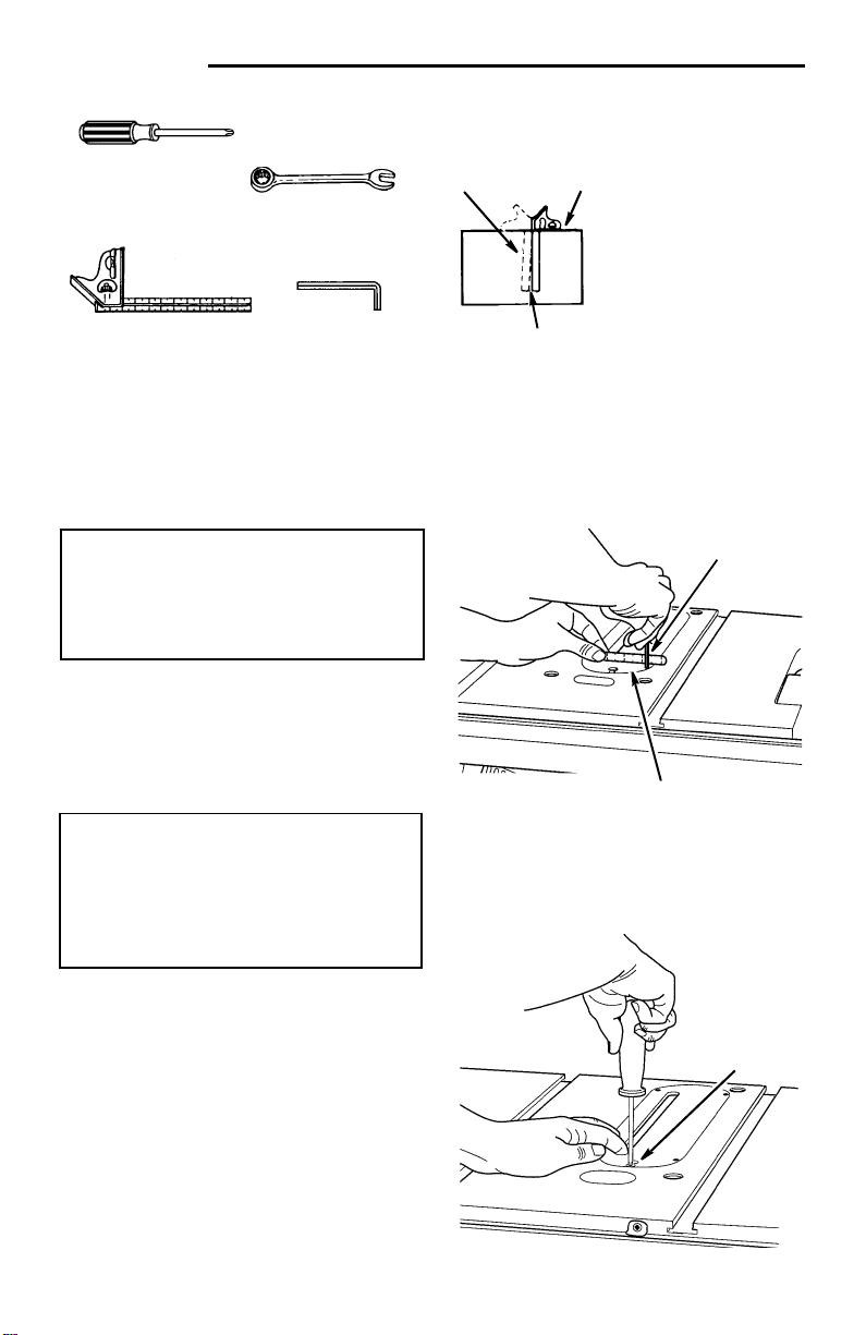
1.Insert should be flush wit h table top.
Check as shown. Loosen fl at head
screw that holds insert and adjust the
four set screws as nec essary. Tighten
flat head screw . Do not tighten sc rew to
the point where it bends the insert.
CAUTION: Insert must be even
with the table surface. Inserts too
high or lo w ca n le t t h e wor kpi e ce
“snag” or catch on uneven
edges. Workpiece could twist
and kickback.
2.To remove insert.
a. Make sure saw is off and unplugged.
b. Loosen flat head screw.
c. Lift insert from front end, and pull
toward front of saw.
3.To repl ace insert.
a. Make sure saw is off and unplugged.
b. Place insert into insert opening in
table and push t oward rear of saw to
engage spring clip and until keyslot
in insert will drop over flat head
screw. Tighten screw .
c. Do not tighten screw to the point
where it bends the insert.
Combination Square must be true. Check
it’s accuracy as shown below.
Draw light line on
board along edge
Combination
Square
Shou ld be no gap or overlap here when
square is flipped over in dotted position.
Select the straight edge of
3/4” thick board. This edge
must be perfect ly straight.
NOTE: The square and
straight edge are used to
align the saw. They must
be accurate if t he saw is
to be aligned properly.
3/32 In.
Hex “L” Wrench
Table Insert
Flat Head
20
Screw
Page 21
Checking Heeling Adjustment or
Parallelism of Sawblade to Miter
Gauge Groove
While cutti ng, the materi al must mov e i n a
straight line parallel to the sawblade.
Therefore, both the mit er gauge groove
and the rip fence must be parallel to the
sawblade.
WARNING: The blade must be
parallel to the miter gauge
groove. Misaligned blades cou ld
bind on workpiece. Workpiece
could suddenly kickback. You
could be cut or hit.
If the sawblade is not parallel to the miter
gauge groove, the blade will bind at one
end of the cut. This is known as “Heeling”.
WARNING: To reduce the risk of
injury from accidental start, make
sure switch is “OFF” and plug is
not connected to power source
outlet.
To check for parallelism:
1.Raise blade all the way up.
2.Mark an “X” on one of the teeth which
is set (bent) to the right .
3.Place the head of a combination
square in the groove. Adjust blade of
square so that it just touc hes the tip of
the marked tooth.
4.Move squa re to rear, rotate blade to
see if marked tooth again touches
blade of square.
5.If tooth touches square the same
amount at front and rear, sawblade is
parallel to mit er gauge groove.
6.If tooth does not touch the same
amount, the mechanism underneath
must be adjust ed to make the blade
parallel to groove.
WARNING: To reduce the risk of
injury from accidental start, make
sure switch is “OFF” and plug is
not connected to power source
outlet.
Marked
Tooth
Combination
Square
Alignment
Sawblade
x
Miter Gauge
Groove
Screws
21
Page 22

Alignment (contin ue d)
NOTE: Always review the sect ion "Check -
ing Blade Parallel to the Miter Gauge
Groove" before proceeding with this section.
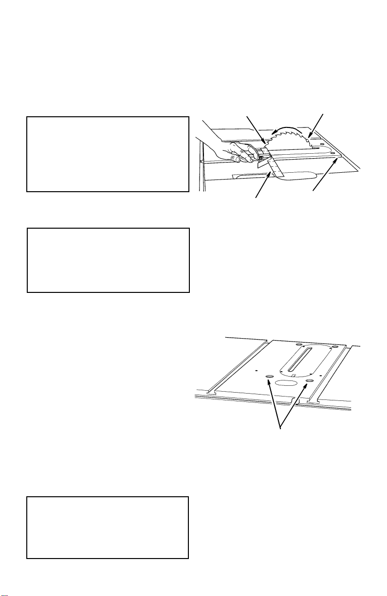
7.Loosen 1/2 t urn the four alignment
screws in the top of tabl e next to the
sawblade. This will allow the mechanism below the table to be shi fted
sideways.
CAUTION: Blade tips are sharp,
to move, grasp blade as shown
to avoid injury.
8.Push on side of blade and move it to
either the right or left as needed to
make the square touch the same
amount front and rear. Tighten one
screw.
9.Check with square to determine i f
marked tooth t ouches square by the
same amount at front and rear.
If it does, alternately tight en the other
three screws.
If it does not, loosen screw and move
blade the required amount.
10.Recheck blade clearance to table
insert to make sur e blade does not hit
at either 90 or 45 degree blade tilt.
Alignment
Screws
22
Page 23

Checking Blade Tilt, or Squareness
of Blade to Table
When the bevel poin ter i s point ing di rectl y
to the “0” mark on the bevel scale, the
sawblade should make a square cut 90°
to the table.
WARNING: For your own safety,
turn switch “OFF” and remove
plug from po we r source outl et .
To Check For Squareness, 90°
Position
1.Raise blade all the way up.
2. Loosen the blade tilt lock lever and push
the elevation wheel in and to the left as
far as possible and tighten the blade tilt
lock lever.
3.Place th e square agai nst blade. Make
sure square is not touching the tip of one
of the saw teeth.
A.If blade is square to table
1.Check pointer. If pointer does not
point to the “0” mark on the bevel
scale, loosen the pointer adj usting
screw and adjust pointer using
medium screwdriver. Reti ghten
screw.
Square
Blade
Pointer at
0° Positio n
B.If blade is not square to table, the
90° stop screw must be adjusted.
1.Loosen 90° stop screw three to
four turns using 5/32 inch hex “L”
wrench.
2.Loosen blade tilt lock lever. Turn
handwheel unti l blade is 90° to t he
table. Tighten blade tilt lock lever.
3.Screw 90° stop screw in unt il it
stops. Check for squareness and
readjust scr ew, if necessary.
4.Check pointer as described in
step A.
90°
Stopscrew
23
Page 24

Alignment (contin ue d)
T o check for alignment, 45° Positi on
1.Loosen the blade tilt lock lever and
push elevati on wheel in and to the right
as far as possible and tighten the blade
tilt lock leve r.
2.Pl ace an accura te squa re ag ainst blade .
Make su r e squa r e is no t touc hin g t he tip
of one of the saw teeth.
A.If blade is 45° to t able;
1.Check pointer. If pointer does not
point to the 45° mark on the scale,
the scale must be a djusted.
2.Loosen two screws on scale and
adjust scale up or down until
pointer points to 45° mark.
Scale Screws
B. If blade is not 45° to table, stop
screw and scale must be adju sted.
1.Loosen 45° stop screw three to
four turns using 5/32 inch setscrew wrench.
2.Loosen blade tilt lock lever. Turn
handwheel unti l blade is 45° to t he
table. Tighten blade tilt lock lever.
3.Screw 45° stop screw in unt il it
stops. Check once again and
readjust scr ew, if necessary.
4.Check point er as described in st ep
A above.
45°
Stopscrew
24
Page 25

Adjusting Rip Fence Guide Bars
Aligning Rip Fence Guide Bars
1.Positi on r ip f ence ove r r ight end of mai n
table. While holding up rear of rip fence
engage front end of rip f ence onto the
front guide bar. Now lower rip fence
down on to tabl e.
2.Open owners manual so that 8 pages
are separat ed from t he r est of the book.
Use these pages like a feeler gage to
set the spaci ng between the bottom of
the fence and the t able top.
3.Rip fence should clear saw tabl e surface just en ough to al low ei ght pa ges t o
slide back and forth under rip fence. If
rip fence is too high or too low, loosen
the four nuts under t he table and the
screw that secures rip scale at front of
main table. Release table lock, positi on
fence inside table extension lock lever.
Adjust front bar up and down as
required. Wrench tighten front right nut
only.
4.Adjus t rear guide bar, as noted above.
Wrench tighten rear right nut.
5. Reposition fence over left end main table.
6.Adjust front guide bar up or down as
needed so the rip fence clears the saw
table surface just enough to allow the 8
pages of the owners manual to sl ide
back and forth under neath the rip
fence. Wrench tighten the front left nut
first and then the ot her remaining two
nuts at the front of the main table.
7.Adjus t rear guide bar, as noted above.
Wrench tighten the rear left nut first
then the other two nuts at the rear of
the main table .
8.Slide fence left and right over main
table to insure clearance.
9.Ti ghten rip scale hold down screw.
Owners Manual
8 Pages
Rip Scale
Hold Down
25
Page 26

Alignment (contin ue d)
Aligning Sliding Table Extension
1. Lock table extension lever.
2.Loosen the four nuts underneath the
sliding table extension.
3.Use a combi nation squar e to make su re
the top of the slidi ng table extension i s
the same height as the mai n table.
4.Ti ghten four nuts. Recheck and readjust if necessary.
Rip Fence Al ignment Ad ju s tm e nt
WARNING: A misaligned fence
can cause kickbacks and jams.
To reduce the risk of injury, follow these instructions until the
fence is pr operly aligned .
The rip fence must be PARALLEL with
the sawblade and miter gauge grooves.
Clean any debris of f the fence gui de bars.
Move fence until it is along the si de of the
right miter gauge groove and lock it. It
should be parallel to groove. If it is not:
a. Unlock fence.
b. Loosen the four hex head screws
located to each side of the rip fence
handle.
c. Place the blade of the combination
square in the right miter gauge
groove as shown.
d. Slide the fence against the blade of
the combination square as shown.
Carefully lock the fence in this position.
e. Alternately tighten the hex head
screws.
f. Recheck alignment.
g. Repeat steps as needed until rip
fence is correctly aligned.
Combination Square
Miter Gauge Groove
Hex Head Screws
for Adjusting Fence
Parallelism
26
Page 27

Rip Fence Lock Lever Adjustment
The rip fence lock lever, when locked
down, should hold the rip fence securely.
The lever should not be dif ficult to push
down and lock.
To assure proper fence lock adjustment:
a. Raise lock lever and push fence
head toward rear of saw.
b. Hold fence head down onto front
guide bar while liftin g rear of fence up
and down.
c. Tighten adjusting nut until fence
clamp just barely touches r ear guide
bar.
d. This should provide the best fence
adjustment possible without over
tightening.
Adjusting Rip Indi cat or
1. Raise the blade up approximately 1".
2.Use a rule r to pos it ion the rip fence 6"
to the ri ght of the blade as shown. Lock
the rip fence.
3.The rip indicator should read 6".
If not:
• Slightly loosen the Phillips head
screw.
• Slide the indicator left or right as
required.
• Tighten the Phillips head screw.
Adjusting
Nut
Fence
Clamp
Rear Guide
Bar
Fence Clamp and Rear Guide Bar
Should Barely Touch When
Fence is Raised
Rip Indicator
6"
27
Page 28

Alignment (contin ue d)
Checking Sliding Table Extension
Lock the table ext ension lock lever. Pullpush on the sliding table extension. It
should not move.
WARNING: To reduce the risk of
thrown workpiece, do not use
with extension lock lever
unlocked.
If the sliding ta ble extension moves
when locked:
1. Release the table extension lock le ver.
2.Find t he fr ont hex coupling locate d
underneath the f ront table.
3.Loosen the hex locking nut.
4.Turn the hex coupling counterclockwise.
5.Lock the table extens ion lock. Pull- push
on the sli ding table extension. Readjust
hex coupling if necessary. Tighten the
hex locking nut aga inst coupling.
Installing Blade Guard
1. Locate the blade guard.
2.Two (2) locator pins are on the blade
guard. These locator pins fit i nto matching holes on a bracket located on the
table saw trunnion.
3.Turn the blade guard loc king knob
clockwise to sec urely attach the blade
guard in place.
Hex Locking
Nut
Front Hex
Coupling
28
Blade Guard
Locking Knob
Pin
Page 29

Aligning Blade Guard
IMPORTANT: To work properly, the
spreader must always be adjusted so the
cut workpiece will p ass on either side of
the spreader without binding or skewing
to the side.
NOTE: The spreader is thinner than the
width of the cut (kerf) by appr oximatel y six
thicknesses of p aper.
1. Raise blade all the way up, making
sure it is square with tabl e.
2. Use a wrench to loosen the screw
that secures the spreader support to
the spreader mount.
3. Raise blade guard. Lift up both antikickback pawls. Insert a large set
screw wrench in the notches of the
pawls to hold the pawls out of the
way.
4. Place a square against the spreader
as shown. Use a wrench to tighten
the screw.
5. Make two folds in a small pi ece (6 x 6
inch) of ordinary newspaper making
three thicknes ses.
The folded paper will be used as
“spacing gauge”.
6. Using 7/16 wrench loosen the 1/4-20
hex head screws so the spreader can
slide sideways.
7. Place rip fence on the right hand side
of table. Carefully move it against
blade so that it is paralle l t o the blade,
and just touches tips of saw teeth.
Tighten ri p fence lock lever.
8. Insert folded paper between spreader
and fence.
9. Hold spreader flat against folded
paper and fence. Tighten screws
using 7/16 inch wrench.
10. To remove blade guard and spreader,
loosen the blade guard locking knob.
Do not loosen other screws. This
allows you to remove and replace the
guard for non-through cuts without
disturbing the spreader alignment.
Spreader
1/4-20 Hex Head Screws
Combination
Square
Kerf
Folded
Paper
Screw
Wood
Blade
Paper
29
Page 30

Alignment (contin ue d)
Removi ng and Installing Sa wb lade
WARNING: To reduce the risk of
injury from accidental start, turn
switch “OFF” and remov e plug
from power source outlet before
removing or installing sawblade.
a. Raise blade guard, remove insert,
elevate blade to its highest point.
b. To r emove blade, hold arbor wrench
securely, pull arbor nut wrench
towards the front of the table.
c. To tighten arbor nut, hold arbor
wrench securely, push arbor nut
wrench towards the rear of the table.
When installing the blade, make sur e
the teeth are pointi ng toward the front
of the saw and that the blade and collars are clean, and fr ee from any burrs.
The hollow side of the col lar must be
against the blade.
Always tighten the arbor nut securely.
NOTE: When using the dado or mold-
ing head, it is not necessary to instal l
the outer (loose) blade collar.
d. Lower the blade below the table.
e. To replace insert, place insert into
opening in table and push toward
rear of saw to engage rear spring on
insert and until key slot in insert will
drop over screw. Tighten screw. Do
not tighten screw to the point where it
will deflect the inser t.
WARNING: To reduce the risk of
injury from a thrown workpiece,
blade parts, or blade contact,
never operate saw without the
proper insert in place. Use the
sawblade insert when sawing.
Use the proper size dado/molding insert for dado blades and
molding he ads.
Open End Arbor
Shaft Wren ch
Tighten
T op Teeth Pointing
to Front of Saw
Closed End
Arbor Nut
Wrench
Collar
Arbor Nut
Blade Insert
WARNING: For your own safety,
turn switch “OFF” and remove
plug from po we r source outl et
before making any adjustments.
30
Page 31

Miter Gauge Alignment
NOTE: The graduations are manufac-
tured to very close tolerances which provide ample accuracy for fine
woodworking. In some cas es where
extreme accuracy is required, when making angle cuts, for example, make a trial
cut and then recheck it.
There are adjustable screw stops for
the stop pin at 0° and 45° right and
left positions for conveniently setting
the miter gauge to cut miters at these
standard angles.
Adjusting Stop Screws
A. Loosen lock nut of screw for 0° stop.
B. Place 90° square against the miter
gauge bar and the face of the miter
gauge head.
C.If adjustment is needed loosen han-
dle of miter gauge. Adjust miter
gauge head flush to squ are. Tighten
lock knob.
D. Adjust sto p sc rew un t il it re s ts
against the stop pin and tighten lock
nut.
E. Adjust 45°, left and right using a 45°
triangle or a protractor of a square
using the above procedure.
The miter gauge head should swivel
smoothly on the bar after the knob is loosened. To adjust this swivel movement:
A. Loosen the knob.
B. Loosen set screw with a 2.5mm hex
wrench.
C.If the head is too loose turn the flat-
head screw in a clockwise direction.
If the head is too tight and wi ll not
swivel smoothly turn the flathead
screw countercl ockwise.
D.Tighten set screw.
Bar
Knob
Adjustment
Screw
Flat Head
Screw
Set Screw
Miter Gauge
Head
Pointer
Stop Pin
31
Page 32

Alignment (contin ue d)
Marking the Ind-I-Cut:
a. With blade 90° (square to table) and
miter gauge in left groove, cross cut
a piece of wood holding the wood
firmly against mit er gauge.
b. Pull miter gauge back until freshly cut
edge of wood is over disk. Using a
sharp pencil, mark a line on disk at
freshly cut edge of wood.
c. With miter gauge in right hand
groove, follow same procedure and
mark another line on disk.
d. These lines indicate the “path” of the
cut (kerf ) m a de by the sa wbla de .
e. When cutting the workpiece, line up
mark on workpiece with line on disk.
NOTE: When the blade is changed, or a
dado/molding head i nstalled these lines
can be erased and reset.
Adjusting Bevel Lock
1. Release blade tilt lock lever and bevel
blade to 45°.
2.Lock blade tilt lock lever, push in to dis-
engage the outer hub of the el evation/
bevel handwheel and wi th moderate
force attempt to move handwheel
toward the 0° bevel.
3.If blade tilt mechanism cannot be
moved, no additional adj ustme nt is necessary.
4.If blade tilt mechanism can be moved
adjust the blade tilt lock nut by rotating
clockwise 1/4 turn.
5.Repeat steps 3 and 4 as necessary.
6.Releas e hub of the elevation/be vel
handwheel and move blade ti lt mechanism back to 0°.
Marking
Ind-I-Cut
Using
Ind-I-Cut
Blade Tilt
Lock Nut
32
Page 33

Mounting Your Saw
Mounting Table Saw to Workbench
or Legse t
WARNING: To reduce the risk of
injury from accidental start,
make sure switch is "OFF" and
plug is not connected to power
source outlet.
WARNING: To reduce the risk of
injury from kickback or saw
movement the saw must be
properly secured to a sturdy
workbench, cabinet or legset.
Casters if provided on the cabinet or legset must be locked
during saw opera tion. If there is
any tendency for the saw to
move or rock during operation,
this must be corrected immediately.
If table saw is to be used in a permanent
location, it should be f astened securely to
a firm supporting surf ace such as a workbench, or legset using the mounting
holes.
Workbenc h M ounting Usi ng
Hardware
When mounting ta bl e saw to a wor kbench
and using a vacuum hookup, holes should
be drilled through t he supporting surface
of the workbench using the dimensions
illustrated.
If a vacuum is not used, an opening must
be made in the workbench using the
dimensions illustrated, so the sawdust
can fall away from the saw base area .
Table Saw Mounting Procedures
1. Locate the proper hole mounting diagram for your desired type of table saw
mounting.
2.Mark the hole locations and cutout
opening if vacuum is not used. Drill the
holes and cut o ut the area to allow sawdust to fall away fro m the base if a vacuum is not being utili zed.
Workbench Surface
4"
16-3/4"
3/8"
15-5/16"
21-5/16"
3"
Diagram of Workbench Mounting Holes
3.Place the tabl e saw on the mounting
surface and al ign the four holes.
4.Insert four (4) 1/4-20 screws that are
long enough for washers and nuts
which will proper ly se cure t he t able saw
to the mounting surface.
NOTE: Mounting hardware (bolts, nuts,
washers etc.) are not supplied with the
saw.
Opening if
Vacuum
is not used
23-3/4"
(Front of Table Saw)
Dia.
33
Page 34

Mounting Your Saw (continued)
Mounting Table Saw to RIDGID
Universal Power Tool Legset
#AC9910
1. Assemble legset per instructions.
2.Locat e the fo ur (4 ) “TS” lay out point s on
the particle board tables.
3.Drill the four (4) above holes.
4.Insert four (4) 1/4-20 screws that are
long enough for washer s and nuts
which will pr operly secure the t able s aw
to the legset. Tighten hardware.
NOTE: Mounting hardware (bolts, nuts,
washers, etc.) are not supplied with the
saw.
Workbenc h M ounting Usi ng " C "
Clamps
An alternative method of securing your
table saw is to fasten the saw base with
"C" clamps.
1. Follow instructions for mounting to
workbench, substitute "C" clamps at
each mounting screw loc ation.
2.Securely clamp saw to workbench
using four "C" clamps, as shown.
Supporting surface where saw is to be
mounted should be examined carefully
after mounti ng to i nsure that no movement can occur during use. If any tip ping,
sliding or walking is noted, secure the
workbench or cabinet befor e operating
the table saw.
(Front and Rear)
Mounting
Screw Location
"C" Clamps
Diagram of Clamping Table Saw
to Workbe n c h
"C" Cl a m p
Supporting Table Saw with
Sawhorses
The table saw has provisions for being
supported by sawhorses. The sawhorse
can be built with the 2" x 4"crosspieces
either vertical or horizontal . Make sure the
sawhorses ar e secure. Holes for securing
unit to sawhorse(s) ar e provided.
34
Page 35

Safety Instructions for Basic Saw Operations
Before Each Use
Inspect your saw.
• To reduce the risk of injury from
accidental starting, turn the switch
off, unplug the saw, and remove
the switch key before raising or
removing the guard, changing the
cutting tool, changing the se tup, or
adjusting anything.
• Check for alignment of moving
parts, binding of moving parts,
breakage of parts, saw stability,
and any other conditions that may
affect the way the saw works.
• If any part is missing, bent or broken in any way, or any electrical
part does not work properly, turn
the saw off and unplug the saw.
T o Reduce the Risk of Injury From Jams, Slips Or Thrown Pieces
(Kickbacks Or Throwbacks)
Inspect Your Blade.
• Choose the right blade or cutting
accessory for the material and the
type of cutting you plan to do.
• Never use grinding wheels, abrasive cutoff wheels, friction wheels
(metal cutting blades) wire wheels
or buffing wheels. They can fly
apart explosively.
• Cut on ly wood, woo d like or plastic
materials. Do not cut metal.
• Choose and inspect your cutting
tool carefully:
- To reduce the risk of cutting tool
failure and thrown shrapnel (broken pieces of blade), use only 10”
or smaller blades or other cutting
tools marked for speeds of 5000
rpm or higher.
- Always use unbroken, balanced
blades designed to fit this saw’s
5/8 inch arbor.
• Replace d amaged or missing parts
before using the saw again.
• Use the sawblade gu ard, spreader
and anti-kickback pawls for any
thru-sawing (whenever the blade
comes through the top of t he workpiece). Make sure the anti-kickback
pawls work properly. Make sure the
spreader is in line with sawblade.
• Remove adjusting keys and
wrenches. Form a habit of checking for and removing keys and
wrenches from table top before
turning saw on.
• Make sure all clamps and locks are
tight and no parts have excessive
play.
- When thru-sawing (making cuts
where the blade comes through
the workpiece top), always use a
10 inch diameter blade. This
keeps the spreader in closest to
the blade.
- Do not over tighten arbor nut.
Use arbor wrenches to “snug” it
securely.
- Use only sharp blades with properly set teeth. Consult a professional blade sharpener when in
doubt.
- Keep blades clean of gum and
resin.
- Never use the saw without the
proper blade insert.
Inspect your work area.
• Keep work area clean.
• Cluttered areas and benches invite
accidents. Floor must not be slippery from wax or sawdust.
35
Page 36

Safety Instructions for Basic Saw Operations (continued)
• To reduce the risk of burns or other
fire damage, never use the saw
near flammable liquids, vapors or
gases.
• To reduce the risk of injury, don’t do
layout, assembly, or setup work on
the table while blade is spinning. It
could cut or throw anythin g hitting
the blade.
Plan your work
• Use the right tool. Don’t force tool
or attachment to do a job it was not
designed for.
Inspect your workpiece.
• Make sure there are no nails or foreign objects in the part of the workpiece to be cut.
• When cutting irregularly shaped
workpieces, plan your work so it
will not slip and pinch the blade:
• A piece of molding for example,
must lie flat or be held by a fixture
of jig that will not let it twist, rock or
slip while being cut. Use j igs or fixtures where needed to prevent
workpiece shifting.
• Use a different, better suited type
of tool for work that can’t be made
stable.
Plan your cut.
• To reduce the risk of kickbacks and
throwbacks which occur when a
part or all of the workpiece binds on
the blade and is thrown violently
back toward the front of the saw:
- Never cut Freehand. Always use
either a rip fence, miter gau ge or
fixture to position and guide the
work, so it won’t twist or bind on
the blade and kickback.
- Make sure there’s no debris
between the workpiece and its
supports.
• Use extra caution with large, very
small or awkward workpieces.
• Use extra supports (tables, saw
horses, blocks, etc.) for any workpieces large enough to tip when
not held down to the table top.
Never use another person as a
substitute for a table extension, or
as additional support for a workpiece that is longer or wider than
the basic saw table, or to help feed,
support or pull the workpiece.
• Never confine the piece being cut
off, that is, the piece not against the
fence, miter gauge or fixture. Never
hold it, clamp it, touch it, or use
length stops against it. It must be
free to move. If confined, it could
get wedged against the blade and
cause a kickback or throwback.
• Never cut more than one workpiece at a time.
• Never turn your table saw “ON”
before clearing everything except
the workpiece and related support
devices off the table.
Plan Ahead To Protect Your Eyes, Hands, Face and Ears
Dress for safety
• Do not wear loose clothing, gloves,
neckties or jewelry (rings, wrist
watches). They can get caught and
draw you into moving parts.
• Wear nonslip footwear.
• Tie back long hair.
• Roll long sleeves above the elbow.
• Noise levels vary wid ely. To reduce
the risk of possible hearing damage, wear ear plugs or m uffs when
using table saw for hours at a time.
36
Page 37

• Any power saw can throw foreign
objects into the eyes. This can
result in permanent eye damage.
Always wear safety goggles, not
glasses, complying with ANSI
Z87.1 (or in Canada CSA Z94.3-
99) shown on package. Everyday
eyeglasses have only impact resistant lenses. They are not safety
glasses. Safety goggles are available at many local retail stores.
Glasses or goggles not in compliance with ANSI or CSA could seriously hurt you when they break.
• For d usty operations, wear a dust
mask along with safety goggles.
Plan the way you will push the
workpiece through.
• Never pull the workpiece
through. Start and finish the cut
from the front of the table saw.
• Nev er put your fingers or hands
in the path of the sawblade or
other cutting tool.
• Never reach in back of t he cu tting
tool with either hand to hold down
or support the workpiece, to
remove wood scraps, or for any
other reason.
• Avoid hand positions wh ere a sudden slip could cause fingers or a
hand to move into a sawblade or
other cutting tool.
• D on’t overreach. Always keep good
footing and balance.
• Push the workpiece against the
rotation of the blade, never feed
material into the cutting tool from
the rear of the saw.
• Always pus h the workpiece all the
way past the sawblade.
• As much as possible, keep your
face and body to one side of the
sawblade, out of line with a possible kickback or throwback.
• Set the cutting tool as low as possible for the cut you’re planning.
Reduce the Risk of Accidental
Starting.
• Make sure switch is “OFF” before
plugging saw into a power outlet.
Whenever Sawblade Is Spinning
WARNING: Don't allow familiarity (gained from frequent use of
your table saw) cause a careless
mistake. Always remember that
a careless fraction of a second
is enough to cause a severe
injury.
• Before actually cutting with the
saw, watch it while it runs for a
short while. If it makes an unfamiliar noise or vibrates a lot, stop
immediately. Turn the saw off.
Unplug the saw. Do not restart until
finding and correcting the problem.
• Make sure the top of the arbor or
cutting tool turns toward the front of
the saw.
Keep Children Away.
• Keep all visitors a safe distance
from the table saw.
• Make sure bystanders are clear of
the table saw and workpiece.
Don’t Forc e Tool.
• Let the blade reach full speed
before cutting.
• It will do the job bet ter and safer at
its designed rate.
37
Page 38

Safety Instructions for Basic Saw Operations (continued)
• Feed the workpiece into the saw
only fast enough to let the blade
cut without bo gging down or binding.
Before freeing jammed material.
• Turn switch “OFF”.
• Wait for all moving parts to stop.
• Unp lug the saw.
• Check blade, spreader and fence
for proper alignment before starting
again.
• To reduce the risk of throwb ack
of cut off pieces.
• Use the guard assembly.
T o remove loose pieces beneath or
trapped inside the guard.
• Turn saw “OFF ”.
• Remove switch key .
• Wait for blade to stop before lifting
the guard.
Before Leaving The Saw.
• Turn the saw off.
• Wait for blade to stop spinning.
• Unplug the saw.
• Make workshop child-proof. Lock
the shop. Disconnect master
switches. Remove the yellow
switch key. Store it aw ay from children and others not qualified to use
the tool.
Work Feed Devices
Before cutting any wood on your saw,
study all of the “Basic Saw Operations”.
As you learn new table saw woodworking
techniques, you’ll see that many type s of
cuts need di fferent support and feeding
devices, known as ji gs or f ixtures. They
can help you make cuts more accurately.
By helping to steady the work piece and
keep you away from the blade, they can
help you safely use your saw for certain
cuts.
Many people custom build their own jigs
and fixture s. Ji gs and fixtures are of ten
designed for a particular cut.
You can use your table saw to easily
make many jigs and fixtures. To get you
started, we’ve included instr uctions for
some simple ones. Af ter you have made a
few practi c e cu ts , ma ke u p the se jigs
before star ting any projects. The use of
these devices is explained in “Basic Saw
Operations” section.
38
Page 39

Push Stick
Make the push stick fr om a piece of solid
wood. Use a piece of 1 x 2 (3/4" x 1-5/8"
actual) by 15" long.
Slightly Less Than Thickness
Of Workpiece Up to 3/8"
Make the featherboard from a piece of 8”
x 24” x 3/4” thick solid wood
24"
Kerfs About
5/16" Apart
Grain
8"
90° Notch
Push Block (For Use with Auxiliary
Fence)
There are any number of ways to properly
cut your workpieces to make a push
block. The following steps describe one
way you can make a push block.
Making the base:
• Start with a piece of 3/8 inch plywood
at least 5-5/8 i nches wide or wider and
12 inches long or longer.
• Make two ripcuts. Perform the first
ripcut along the side of the 3/8" wide
strip. Next, ripcut the 3/8" plywood to a
width of 5-1/8".
• Crosscut the 3/8" plywood to 12" long.
• Crosscut a 2-1/2" piece off the 3/8"
wide by 3/8" thick strip and save this
short piece for later.
The next cut s will creat e the 3/8 " by 9 -1/2"
notch in the base. Mark the long edge of
the board 2-1/2" from one end. Ma ke a
crosscut into the edge on t he mar k, stopping about 3/4" into the board. Set the
saw and rip the width to 4-3/4" along the
same edge as th e stopped crosscut. Stop
the ripcut where the two cuts intersect.
Turn off the saw and remove the base
piece. The base should now measure as
shown.
Material for Push Bl o c k
At Leas t 12"
4-1/2"
3/8" Thick Plywood
5"
At Leas t 12"
Handle
Cutting Out the Base
2-1/2" (save)
4th Cut
1st Cut
2nd Cut
12"
Creating the Notch
1st Cut
2nd Cut
2-1/2"
Finished Base
12"
At Least
5-5/8"
2-1/2"
3/8"
4-3/4"
3rd Cut
At Least
5-5/8"
3/8"
5-1/8"
4-3/4"
These Edges
Must Be
Parallel
3/8" T hick Plywood
Base
At Least
5-5/8"
39
Page 40

Work Feed Devices (continued)
Making the handle:
• Miter crosscut a piece of 3/4 inch thick
plywood to shape and size sho w n:
NOTE: The mitered corners can be any
size that looks like the drawing (about 1-1/2"
by 1-1/2").
Putting it Together
• Using good quality woodworking glue,
glue the 3/8" x 3/8" x 2-1/2" piece strip
saved earlier to the base as shown.
IMPORTANT: Do not use nails or screws.
This is to prevent dulling of the sawblade
in the event you cut into the push block.
• Position the handle at the center of the
plywood base as shown. Fasten them
together with glue and wood sc rews.
IMPORTANT: Make sure the screw heads
do not stick out from the bottom of the
base, they mu st be flush or recessed. The
bottom must be flat and smooth enough
to slide along the auxiliary fence you are
now ready to make.
Auxiliary Fence
Making the base:
• Start with a piece of 3/8 inch plywood
at least 5-1/2 i nches wide or wider and
25-1 /2 inc hes lo ng or long er.
• Cut the piece to shape and size shown:
Making the side:
• Start with a p i ece of 3 /4 i nc h pl y wo od at
least 3 i nche s wi de or w ide r and 2 5-1 /2
inches long or longer.
• Cut the piece to shape and size shown:
• Optional: Drill three (3) holes in plyw ood
side similar to rip fence wood facing (see
page 31). The plywo od s ide m ay ei the r b e
mounted to the ri p fence usi ng these th ree
holes and appropriate nuts and bolts or
clamped to th e fence wit h “C” cl am ps.
Putting it together:
• Put the pieces together, as shown:
IMPORTANT: Make sure the screw heads
do not stick out from the bottom of the
base, they mu st be flush or recessed. The
bottom must be flat and smooth enough
to rest on the saw table without rocking.
40
3/4" Plywood Handle
3/8" Plywood Base
Glue
Only
Screw Head Must Be
Flush Or Recessed
Cutting Out the Base
25-1/2"
3/8" Thick Plywood Base
Cutting Out the Side
25-1/2"
3/4" Thick Plywood Side
Finished Auxiliary Fence
4-3/4"
3/8"
Plywood
This face and this edge
must be parallel
5-1/2"
3"
3/4" Plyw ood
Page 41

Fence Facing
Select a piece of smooth straight wood
approximately 3/4 inch thick, and the
same length as the rip fence.
Attach it t o the f enc e with the three squ are
head bolts, nuts and washers. (See
“Hardware for Attac hing Wood Fac in g”) in
Repair Parts Figure 4. To remove the facing, loosen the hex nuts, slide the facing
toward the rear and out of the f ence slot.
If the fence facing is for use with feather
boards, it will need to be about 8" tall. For
use with molding heads and dado blades
the width should be at least 3".
3"
Minimum
1-3/8
3/4"
Counterbore
3/4 Diameter
x 3/8 Deep
9/32
Diameter
Hole
Fence
Square Head
Bolt
Flat
Washer
Hex
Nut
Lockwasher
Wood Facing
41
Page 42

Basic Saw Operations
Using the Miter Gauge
The miter gauge is used when crosscutting, miter cutting, bevel cutting, compound miter cutting, dadoing and when
rabbeting across the end of a narrow
workpiece.
WARNING: For your own safety,
always observe the following
safety precautions in addition to
the safety instructions of pages 3
thru 9 and 35 thru 38.
Additional Safety Instructions for
Crosscutting
Before Starting:
•Never use the ri p fence when crosscut-
ting except as specifically inst ructed.
Crosscutting
Definition: A cutti ng or shaping operation
made across the width of a workpiece.
The graduations on the miter gauge provide ample accuracy f or average woodworking. In some cases where extreme
accuracy is required, make a trial cut and
then recheck it with a prec ision square, or
protractor.
NOTE: The space between the miter
gauge bar and the groove in the table is
held to a minimum during manuf acturing.
For maximum accuracy when using the
miter gauge, always favor one side of the
groove in the table. In other words, don’t
move the miter gauge from si de to side
while cutting but keep one side of the bar
riding against one side of the groove.
NOTE: Gluing a piece of sandpaper to the
face of the miter gauge head can help
prevent the workpiece from “creeping”
while it is being cut.
The miter gauge head is locked in position by twisting th e lock knob clockwise.
Always tighten it secu rely when in use.
WARNING: To reduce the risk of
blade contact or kickback, hold
miter gau ge properly.
•An auxiliary wood facing attached to the
miter gauge can help prevent workpiece twisting an d throwbac ks. Attac h it
to the slots provided. Make the facing
long enough and big enough to support
your work. Make sure, however, it will
not interfere with the sawblade guard.
•Use jigs or fixtures to help hold any
piece too small to extend across t he fu ll
length of the miter gauge face during
the cut. This let s you properly hold the
miter gauge and workpiece and helps
keep your hands away from the blade.
While cu tting:
•To reduce the risk of blade contact,
always hold the miter gauge as shown
in the this section.
The miter gauge may be used in ei ther of
the grooves in th e table.
When using the miter gauge in the left
hand groove, hold the workpiece firmly
against miter gauge head with your left
hand, and grip the lock knob with your
right hand.
When using the miter gauge in the right
hand groove, hol d the work piece with
your right hand and the lock knob with
your left hand.
Always Support
Sandpaper
Long Workpieces
42
Page 43

Crosscutting (continued)
Slots are provided in the miter gauge for
attaching an auxiliary facing to make it
easier to cut very long or short pieces.
Select a suitable piece of smooth wood,
drill two holes through it and attach with
screws. Make sure the facing does not
interfere with the proper operation of the
sawblade guard.
When cutting long work pieces, you can
make a simple support by clamping a
piece of pl ywood to a sawhorse. (As seen
on previous page.)
Repetitive Crosscutting
Definition: Cutti ng a quan tity of pi eces the
same length without having to mark each
piece.
•Follow al l safety precautions and operational instructions for cross cutting.
•When making repetitive cuts from a
long workpiece, ma ke sure it is adequately supported.
WARNING: Never use the rip
fence as a direct length stop
because the cutoff piece could
bind between the fence and the
blade causing a kickback.
•When making repetitive cuts shorter
than 6 inches, clamp a bl ock o f wood 3”
long to the fence. Plac e fence at
desired position to act as a length stop.
•Slide t he workpiece along the miter
gauge until it touches the block...hold
the workpiece sec urely against the
miter gauge.
•Make the cut...turn the saw off...remove
the piece aft er t he blade has stopped
and before cutting the next piece.
WARNING: To reduce the risk of
kickback from twisting the workpiece, when clamping the block
make sure that the end of the
block is well in front of the sawblade. Be sure it is clamped
securely.
Lock
Knob
Stop P i n
Miter Gauge
Head
45° Stop
Screw
“C” Clamp
Cut Off Piece
Auxiliary
Facing
Wood Block
43
Page 44

Basic Saw Operations (continued)
Miter Crosscutting
Miter cutting is cutting wood at an angle
other than 90° with the edge of the wood.
Follow the same procedur e as you would
for crosscutting.
•Adjus t th e miter gauge to the desired
angle, and lock i t.
•The mite r gauge may be used in either
of the grooves in the table. Make sure it
is locked.
•When using the miter gauge in the left
hand groove, hold t he workpiece firmly
against the miter gauge head with your
left hand, and grip the lock knob with
your right hand.
•When using t he miter gaug e in the right
hand groove, hold the workpiece with
your right hand and the lo ck knob with
your left hand.
Bevel Crosscutting
Bevel crosscu tt ing is the same as crosscutting except that the wood is cut at an
angle...other than 90° with the bottom flat
side of the wood.
•Adjust the blade to the desi red angle.
•Always use the miter gauge in the
groove to t he right of the blade. It cannot be used in the groove to the left
because the blade guar d wil l interfere.
Hold the workpiece with yo ur rig ht hand
and the lock knob with your left hand.
•Use the auxil iary fence/ work support for
additional support of the workpiece.
Compo und Crossc utt i ng
Compound cutting is a combination of
miter cutting a nd bevel crosscutt ing. The
cut is made at an angle other than 90° to
both the edge and the bottom flat side of
the wood.
•Adjus t the miter gauge and the blade to
the desired angl e...Make sure miter
gauge is locked.
44
Page 45

Using the Rip Fence
Ripping, bevel ripping, resawing and rabbeting are performed using the rip fence
together with the auxi li ary fence/work
support, push stick or push block.
WARNING: For your own safety,
read and always observe all
safety precautions listed in manual and on saw.
Additional Safety Instructions for
Rip Cuts
•Never use the mit er gauge when ripping
•Use a push stick whenever the fence is
2 or more inches from the blade.
•When thru sa wing, use an auxiliary
fence and push block whenever the rip
cut is between 1/2 and 2 inches from
the blade.
•Never thru saw r ip cuts narrower than
1/2 inch.
•Never rip anything shorter than 10”
long.
•When using a push stick or push block,
the trailing end of the workpiece must
be square. A push stic k or block against
an uneven end could sli p off or push the
workpiece away from the f ence.
•A featherboard can help guide the
workpiece. (See “Basic Saw OperationUsing Featherboards for Thru Sawing”
section.)
•Always use featherboards for any nonthru sawing rip type cut s. (See “Basic
Saw Operations-Using Featherboards
for Non-thru sawing” section)
Before Starting:
•To reduce the risk of kickbacks and
slips into the bl ade, make sure the rip
fence is parallel to the sawblade.
•Befor e t h ru sawing, ch eck th e a nti-kickback pawls. the pawls must stop a kickback once it has started. Replace or
sharpen anti-kickback pawls when
points become dull.
•Plastic and composition (like hardboard) materials m ay be cut on your
saw. However, since these are usually
quite hard and slippery, the anti-kickback pawls may not stop a kickback.
Therefore, be espe cially careful in your
setup and cuttin g procedures.
While Thru sawing:
•To reduce the risk of kickbacks and
slips into the bl ade, always push forward on the section of the workpiece
between the sawblade and the rip
fence. Never push f orward on th e piece
being cut off .
45
Page 46

Basic Saw Operations (continued)
Ripping
Definition: Cutti ng operation along the
length of the workpiece.
Position the fence to the desired width of
rip and lock in place.
Befor e starting to rip, b e s ur e :
1. Ri p fence is parallel to sawblade.
2. Spreader is properly aligned with sawblade.
3.Anti-kickback pawls are functioning
properly.
When ripping l ong b oards or lar ge p anels,
always use a work support. A simpl e support can be made by clamping a pie ce of
plywood to a sawhorse.
WARNING: To reduce the risk of
kickback, push forward only on
the part of the workpiece that
will pass between th e blade and
the fence.
Keep your hands out of the blade path.
Feed the workpiece by pushi ng forward
only on the part of the workpiece that will
pass between the blade and the fence.
Stop your l eft thumb at the front edge of
the table. Finis h the cut wit h the appropriate pusher.
Feed
Force
Blade
Path
Use the micro-adjus t mechanis m to make
fine adjustment s to t he rip fence. To move
the rip fence push in on the m icro-adjust
knob and rotate.
Once the trailing end is on the tabl e:
When “width of rip” is 2" or wider, use the
push stick to push the work al l the way
past the blade.
Push Stick
46
Page 47

Ripping ( c on t in ued)
When “width o f rip” is na rrower than 2 " th e
push stick cannot be used because the
guard will interfere...use the auxi li ary
fence and push block.
Attach auxi liar y fenc e to r ip fe nce wit h t wo
“C” clamps or use “T” slot and hardware.
Auxiliary
Fence
“C” Clamp
Feed the workpiece by hand along the
auxiliary fence until the end is approximately 1" past the fr ont edge of the table.
Continue to feed using the push block.
Hold the workpiece in posi tion and install
the push block by sliding it on top of the
auxiliary fence/work support (this may
raise guard).
WARNING: To reduce the risk of
injury from blade contact never
thru saw cuts narrower than 1/2"
wide.
Narrow strips thi cker than the auxiliary
fence/work suppor t may enter the guard
and strike the baff le. Car efully r aise gua rd
only enough to clear the work piece. Use
push block to complete cut.
Workpiece
Baffle
Push Block
Auxiliary Fence
Bevel Ripping Narrow Work
When bevel ripping mate rial 6” or narrower, use fence on the right side of the
blade only. This will provide more space
between the fence and the sawblade for
use of a push stick. If the fence is
mounted to the left, the sawbla d e gua r d
may interfere with pr oper use of a push
stick.
47
Page 48

Basic Saw Operations (continued)
Using Featherboards for Thru
Sawing
Featherboards ar e not employed for thru
sawing operations when using the miter
gauge.
Featherboards ar e used to keep the work
in contact with the fence and table as
shown, and to help stop kickbacks.
Add a 7-1/2” high flat facing board to the
fence, the f ull length of the fence. The facing board may either be “C”-clamped to
the rip fence or held in place with appropriate nuts and bolt s (see “Workfeed
Devices” section).
Mount featherboar ds to facing board and
table as shown, so tha t l eading edges of
featherboards wil l support workpiece.
WARNING: Make sure the featherboard against the edge
presses only on the uncut portion (in front of the blad e) . It
might otherwise pinch the blade
in the kerf and cause a kickback.
Before starting the operation (switc h
“OFF” and blade below table surface):
1. Install featherboards so they exert
pressure on the workpiece; be positive
they are securely att ached.
2.Make sure by trial that the featherboards will stop a kickback if one
should occur.
Work
Support
Featherboard
Featherboard
“C” Clamps
Facing
Board
Workpiece
Push
Stick
48
Page 49

Using Featherboards for Non-Thru
Sawing
Featherboards ar e not employed during
non-thru sawing operations when using
the miter gauge.
Use featherboards for all other non-thru
sawing operations (whe n sawbl ade guard
must be removed). Featherboards are
used to keep the work in contact with the
fence and table as shown and to stop
kickbacks.
Add a 7-1/2” high flat facing board to the
fence, the full len gth of the fence.
Mount featherboar ds to facing board and
table as shown, so tha t l eading edges of
featherboards will support workpiece until
cut is complete, and the workpiece has
been pushed completely past the cutter
(sawblade, dado-head, etc.) with a push
stick, as in rippi ng.
Before starting the operation (make sur e
the switch is in the of f position and the
blade is below the table):
1. Install featherboards so they exert
pressure on the workpiece; be positive
they are secure.
2.Make su re and t ry out the set-up to verify that the featherboards are correctly
positioned.
WARNING: For your own safety,
replace the sawblade guard as
soon as the non-thru sawing
operation is complete.
Work Support
“C” Clamp
Featherboard
Featherboard
“C”
Clamp
Facing
Board
Push Stick
49
Page 50

Basic Saw Operations (continued)
Resawing
Resawing is a rip cut made in a piece of
wood through its thickness. The piece is
typically posit ioned on its edge. If the
piece is narrower than 3- 3/8" it can be
resawn in one pass with the blade guard
in place. Extra supports or fixtures will be
required when the edge resti ng on the
table is too narrow fo r th e piece to be stable or when the fence interferes with the
blade guard. (See metho d d escribed
below)
WARNING: Do not attempt to
resaw bowed or warped material.
It can’t be properly supported. It
could kickback or bind.
NOTE: To resaw a piece of wood wider
than 3-3/8”, or a piece needing extra support, it will be necessary to remove the
blade guard and use the auxi li ary fence/
work support. (See “W orkfeed Devices”.)
Construct an auxiliary fence/work support
as shown. Depending on the thickness of
the workpiece the widt h of the auxiliary
fence/work support wi ll have to be made
so that it can be attached to the table saw
top with “C” clamps. Clamp the auxi liary
fence/work sup port t o the t able so that th e
workpiece will sl ide easily without bi nding
between the two fences and it will not t il t
or move sideways.
Auxiliary Fence/
Work Support
WARNING: For your own safety
1. Do not “Backup” (reverse
2. Make first pass to a depth
3. Keeping the same face of
WARNING: For your own safety,
install blade guard immediately
upon completion of the resawing operatio n.
Workpiece
feeding) while resawing
because this could cause a
kickback.
slightly more than one half the
width of the board.
board against the fence rotate
it end over end and mak e the
second pass.
Using Carbide Tipped Blades
WARNING: To reduce the risk of
cutting tool failure and thrown
shrapnel (broken pieces of
blade) read and understand all
the warnings and instructions
which come w ith carbide tipped
blades. Failure to heed all carbide tipped blade warnings and
safety instructions c an result in
serious injury.
Carbide is a very hard but brittle materi al.
Take care when mounting, using and storing carbide blades to pr event accidental
damage. Slight shocks, such as striking a
tip during handli ng, can s erious ly d amage
the blade. Fore ign objects in the workpiece, such as wir e or nai ls, can also
cause ti ps to cr a ck or br eak off.
Before using a car bide tipped blade,
always examine the blade and tips for
damage. Look for bent teeth, a bent
blade, cracks, broken, missin g or loose
carbide tips. Do not use a carbide tipped
blade if damage is found or suspected.
Do not use a carbide tipped blade witho ut
all appropr iat e guards in place.
Mount blade securely in proper rotation
direction.
Never rotate a carbide tipped blade faster
than its maximum recommended speed.
50
Page 51

Dadoing
Dadoing is cutting a groo ve int o the workpiece. There are a wide variety of dado
heads available - be sure and consult the
specific instr uctions included with your
dado head.
WARNING: For your own safety;
always read, understand and follow all directi ons in the instructional book l et furnished with t he
dado head.
The slot provided for the saw blade in the
regular table insert is too small for t he
dado head to pass through. Therefore, a
special dado insert must be purchased.
WARNING: For your own safety,
always use dado insert listed
under recomm end ed acces sories.
A dado is never used for thru sawing or
cutting compl etely through a workpiece. It
is used for non-thru sawing, cutting part
way into the workpiece. Therefore, the
blade guard and spr eader c annot be used
and must be removed. Use caution. Use
miter gauge, rip fence, featherboards,
push sticks, or fence facing board as
required.
WARNING: For your own safety,
always replace the blade, table
insert, guard and spreader when
you are finished dadoing.
The dado head is assemb led to the saw
arbor in the same manner as the saw
blade. The arbor on the saw, is long
enough so that the widest cut that can be
made is 13/16" wi de. It is no t neces sar y to
instal l the outside loose collar before
screwing on the arbor nut. Make sure the
arbor nut is tight .
When cutting a “deep ” dado or a wide
groove it is nec essary to remove only a
small amount of mater ial (1/8"-1/4" ) at a
time. Continue to in crease dado eleva tion
until the desired depth is reached.
Dado
Insert
Saw
Arbor
51
Page 52

Basic Saw Operations (continued)
Rabbeting
Rabbeting is known as cutting out a section of the corner of a piece of material,
across an end or along an edge.
To make a rabbet requires cuts which do
not go all the way through the mat eri al.
Therefore, the blade guar d must be
removed.
1. Remove blade guard.
2.For rabbeting along an edge (long way
of workpiece) as shown add facing to
rip fence approximately as high as the
workpiece is wide. Adjust rip fence and
blade to required dimensions; then
make first cut wi th board flat on table as
any rip (t ype) cut; make second cut with
workpiece on edge. Follow all precautions, safety instructions, and operational instructions as for ripping, or rip
type operations, including featherboards and push stick, etc.
3. For rabbeting across an end, for workpiece 10-1/2” and narrower, make the
rabbet cut with the board flat on the
table. Using the miter gauge fitted with
a facing, follow the same procedures
and instructions for cross cutting making successive cuts across the width of
the workpiece to obtain the desired
width of c ut. Do not use the rip fence for
rabbeting acr oss the end.
WARNING: For your own safety,
install blade guard immediately
upon com pletion of rab beting
operation.
Some rabbet cuts can also be made in
one pass of the workpi ece over the cutter
using a dado head.
Rabbet
Second
Cut Etc.
First
Cut
This Side
Against Fence
When Making
Second Cut
Second Cut
First Cut
Rabbet
Ploughing and Molding
Ploughing is grooving with the grain the
long way of the workpiece, us ing the
fence. Use featherboards and push sticks
as required.
Ploughing
52
Page 53

Molding
Molding is cutting a shape on the edge or
face of the workpiece. With a mo ldi ng
head and a selection of different knife
shapes it i s pos si ble f or almost a ny ki nd of
molding (base, cove, bead, etc.) to be
produced.
There are a wi de vari ety o f mol ding heads
available as well as many different
shapes of knives. Be sure and con sul t the
specific instr uctions included with your
molding head.
WARNING: For your own safety;
always read, understand, and follow all directi ons in the instructional book l et furnished with t he
molding he ad.
The slot provided for t he sawblade in the
regular table insert is too small for t he
molding head to pass through. Therefore,
a special dado/mol ding insert must be
purchased.
WARNING: For your own safety,
always use molding insert listed
under recomm end ed acces sories.
When using the molding head it will be
necessary to remove t he blade guar d and
spreader. Use caution. Use miter gauge,
fence, featherboar ds, push stic ks or fence
facing board, et c., as required.
WARNING: For your own safety,
always replace the blade, table
insert, guard and spreader when
you are finished molding.
A typical molding head i s shown, The various shapes of knives are fi tted into
grooves in the cutterhead and secured
with a screw(s).
The molding head is assembl ed to the
saw arbor in the sa me manner as th e saw
blade. It is not necessary to install the outside loose collar bef ore screwing on the
arbor nut. Make sure the arbor nut is tight.
It is necessar y to use an auxiliary fence
when shaping edges of a work piece.
Position th e auxiliary fence over the cut terhead with the cutter head below the
surface of th e saw ta ble. Turn the saw
“ON” and slowl y rais e the cut terhead . The
cutterhead will then cut its own groove in
the auxiliary fence.
Molding
Auxiliary Fence
53
Page 54

Maintaining Your Table Saw
Maintenance
WARNING: For your own safety,
turn switch “OFF” and remove
plug from po we r source outl et
before maintaining or lubricating
your saw.
•Do not allow sawdust to accumulate
inside the saw. Frequently blow out any
dust that may accum ulate inside the
saw cabinet and the motor.
•Clean y our cutti ng tools with a gum and
pitch remover.
•The cord and the t ool should be wiped
with a dry clean cloth to prevent deterioration from oil and grease.
•A coat of furniture paste wax applied to
the table will help to keep the surface
clean and al low workpieces to slide
more freely.
•If the power cord i s worn, cut, or damaged in any way, have it replaced
immediately.
Anti-Kickback Pawls
Make sure the teeth of the anti -kickback
pawls are alway s sharp. To sharpen:
1. Remove blade guard.
2.Rotate pawl toward rear of spreader so
that teeth are above top of spreader.
Anti-Kickback
Pawl
Spreader
Round
File
Teeth
3. Hold spreader with left hand and place
pawl over corner of workbench as
shown.
4. Using a small round file (smooth cut)
sharpen the t eeth.
5.Reinstall blade guard .
Adjustin g N y lon Set Scre w
If the sawblade has a very slight amount
of lateral move ment (lef t-right movement ),
or if the sawblade is e levate d and tends to
lower itself sl ightly, the nylon set screw
needs to be tightened.
1. Bevel the sawblade to 45°.
2.Locate the 10-32 x 3/4 nylon set screw
and nut. Reference service key #27 &
28 page 48. See illustration.
3.Turn the nut counterclockwise to
loosen.
4.Ti ghten the set screw.
5.Reti ghten the nut.
6.Bevel the sawblade back to 90°.
Nylon Screw
and Nut
Bottom View of Saw
54
Page 55

WARNING: To reduce the risk of
injury from unexpected starting
or electrical shock, unplug the
power cord before working on
the saw.
WARNING: To reduce the risk of
electrical shock, fire or injury,
use only parts identical to those
identified in the parts list reassemble exactly as original
assembly to reduce the risk of
electrical hazards.
Replacing Carbon Brushes
The carbon brushes furnished will last
approximately 50 hours of running time or
10,000 on/ off cy cles . Replace both carbon
brushes when either brush has less than
1/4" length of carbon rem aini ng. To
inspect or replace first unplug the saw.
Lower blade all the way, bevel to 45° and
lock. Turn saw upside down. Then remove
the motor cap on the end of the motor by
removing 2 screws. NOTE: To reinstall the
same bru s h e s, first make sure the
brushes go back in the way they cam e
out. This will avoid a break in period that
reduces performance and increases wear.
Remove the lead wires from the tabs on
the brushes, t hen pull out the br ushes. To
reassemble reverse the procedure.
Tighten the screws snugly but do not
overtighten.
Lubrication
The saw motor bearings and gear case
have been pack ed at the factory with
proper lubricant and require no additional
lubrication. The following parts should be
oiled occasionally with SAE no. 20 or no.
30 engine oi l.
1. Elevation screw threads. (First clean
with a solvent recommended for gum
and pitch removal ).
2.Bearing points in blade guard and miter
gauge.
2
2
2
RIDGID Recommends the Following Accessories
Item SKU No.
Table Saw Miter Gauge
Hold Do w n Cla m p. ... .............. ... .. .AC1022
Dado/Molding Insert.....................AC1040
Zero Cl e a rance Inse rt....... ... .. ......AC1045
Universal Power Tool Legset.......AC9910
Do not use any accessory unless you
have received and read complete instructions for its use.
NOTE: AC1025, AC1030 and AC1035
Blade Insert s are not compatible wi th t his
saw.
WARNING: Use only accessories
recommended for this saw.
Using other accessories may be
dangerous.
55
Page 56

Troubleshooting
WARNING: For your own protection, turn switch “OFF” and always
remove pl ug fr om power source ou t let be fore troubl es ho ot i ng .
General
T rouble Probable Cause Remedy
Excessive
Vibration
Cannot make
square cut when
crosscutting.
Cut binds, burns
or stalls motor
when ripping.
Cut not true at
90° or 45° bevel
positions.
Elevating hand wheel turns
hard.
1. Blade out of balance or
damaged
1. Miter gauge not
adjusted properly.
1. Dull blade or improp er
tooth set.
2. Blade is heeling.
3. Warp ed board
4. Rip fence not parallel
to blade.
5. Sp reader out of align-
ment.
1. Indexes not prop erly
adjusted.
1. Sawdust on threads of
elevating screw.
1. Replace blade.
1. See “Adjustment s” section “Miter
Gauge.”
1. Sharpen or replace blade.
2. See “Alignment ” sect ion, “Heeling
Adjustment”.
3. Make sure concave or hollow side is
facing “down” feed slowly.
4. See “Alignment ” section, “Aligning
Rip Fence.”
5. See “Alignment ” section, “Installing
Blade Guard.”
1. See “Alignment ” sect ion, “Blade Tilt,
or Squareness of Blade to Table”.
1. See “Maintenance ” and “Lubricati on”
sections.
56
Page 57

Motor
NOTE: Motors used on wood working tool s are particularly susceptible to the accum u-
lation of sa wdust and wood ch ips a nd sho uld be bl own o ut or “ Vacuumed” frequently to
prevent interf erence with normal motor ventilation.
Trouble Pro bable Cause Remedy
Excessiv e Noise 1. Motor 1. Have motor ch eck ed b y qualified
service technician. Repair service is available at your nearest
Auth orized Serv ice Center.
Motor fails to
develop full
power. NOTE:
Low Voltage:
(Power output of
motor decreases
rapidly with
decr ease in volt age at motor terminals.
Motor starts
slowly or fails to
come up to full
speed
Motor overheats 1. Motor overloaded
Motor stalls
(resulting in
blow n fuses or
tripped circuit
breakers)
1. Circuit overloaded with lights,
appliances and other motors.
2. Wiring circuit (extension cord)
too long or undersize.
3. General ove rl oading of power
company facilities. (In some
sections of the country,
demand for electrical power
may exceed the capacity of
existing generating and distribution systems.)
4. Incorrect fuses or circuit
breakers in power line.
1. Low voltag e.
2. Windings burned out or open.
2. Impr oper coolin g. (Air circulation restricted through motor
due to sawdust, accumulating
inside of saw.)
1. Voltage too low to permit
motor to reach operating
speed.
2. Fuses or circuit breakers do
not have suffi c i ent cap acity.
1. Do not use other appliances or
motors on same circuit when
using the saw.
2. Increase wire sizes, or reduce
length of circuit. See “Motor
Specifications and electrical
Requirem ent s” sect i on.
3. Request a voltage check from
the power company.
4. Install correct fuses or circuit
breakers.
1. Request voltage check from the
power company.
2. Have motor repaired or repla ced.
1. Feed work slow er into blade.
2. Clean out sawdust to provide
normal air circulation through
motor. See “Maintenance” and
“Lubrication” section.
1. Request voltage check from the
power company.
2. Install p rope r size fuses or circuit
breakers.
Frequent opening of fuses or
circuit breakers
Motor runs intermittently, sparks
excessively or
fails to start
1. Motor overloaded
2. Fuses or circuit breakers do
not have suffi c i ent cap acity.
1. Worn or damaged brushes 1. Replace brushes. See “Mainte-
1. Feed work slow er into blade.
2. Install p rope r size fuses or circuit
breakers.
nance” section.
57
Page 58

Repair Parts
RIDGID parts are available on-line at www.ridgidparts.com
55
54
11
53
43
44
47
46
50
40
Parts List for RIDGID 10 Inch Table Saw
Model No. TS24001
Figure 1
1
2
45
41
44
57
10
61
43
58
5
4
59
6
16
17
19
65
49
13
56
60
52
51
48
42
18
11
3
4
5
1
15
9
66
See Figure 5
7
2
1
8
12
13
14
67
68
39
36
34
35
30
29
28
63
33
31
27
38
37
24
58
32
64
26
20
21
62
22
See Figure 3
23
See Figure 4
25
Page 59

Repair Parts
RIDGID parts are available on-line at www.ridgidparts.com
Always Order by Part Number - not by Key Number
Parts List for RIDGID 10 Inch Table Saw
Model No. TS24001
Figure 1
Key
Part No. Description
No.
126317
1
827518
2
827545
3
73352
4
827478
5
159572-146
6
830397
7
809813-1
8
827872
9
104879
10
827533
11
830345
12
448013
13
830378
14
830396
15
827497
16
827870
17
808380-2
18
829971-8
19
9420474
20
826395
21
AC1000
22
808380-18
23
808275-4
24
827493
25
808380-5
26
830399
27
805475
28
830398
29
169123-2
30
138164
31
827925
32
827873
33
827921
34
827548
35
* Bolt Carriage 1/4-20 x 1
Mount Rail Extension
Table Extension
* Nut Hex Flange 1/4-20
Clip Fence
* Screw Hex Wash Hd Ty T
10-32 x 7/8
Scal e Rip
Screw Pan Rec 6-32 x 1/2
Spring Rip Scale
Screw Lock Set 10-32x3/16
Slider Rail
Cap Rail Front Right
* Screw Pan Hd Ty Ab N8x1/2
Rail Front
Cap Rail Front Left
Panel Front
Scale Bevel
* Screw Pan Hd #8 x 3/8
Base w/ Labels
* Screw Hex Wash Hd Ty T
10-32 x 1/2
Bezel Switch
†Key Switch
Screw Pan Hd #6 x 3/4
Plastite
* Screw Pan Hd 8-32 x 3/8
Foot Base
* Screw Pan Hd #8 Plastite
Plate Switch Box
* N ut H ex 8-32
Box Switch
Relief Strain
* Lockwasher #8
Bolt C arriag e 1/2-13 x 1-1/2
Nut Push 1/2
Washer Flat Nylon
Wrench Arbor
Key
Part No. Description
No.
827874
36
808380-17
37
805550-5
38
830405
39
830406
40
274622
41
821521
42
827463
43
827482
44
827515
45
827523
46
827515-1
47
830377
48
827514
49
274205
50
805552
51
813051-5
52
830376
53
827645
54
827525
55
827470
56
509492
57
809374
58
826390
59
805297-12
60
138671
61
826347
62
829971-7
63
829971-6
64
805549-22
65
SP6499
66
SP6499S
67
SP6499F
68
* Standard Hardware Item - May be pur chased locally
† These parts are available where you purchased your saw.
Nut Wing Nylon 1/2-13
* Screw Pan Hd #10 x 3/4
Plastite
Washer 7/32 x 5/8 x 1/16
Cord w/Plug
Wrap Cord
Screw Hex Hd Ty T
1/4-20 x 1
Screw Hex Hd Shoulder .312
Bolt T 1/4- 20
Coupling 1/4-20
Link Locking Front
Pivot Linkage
Link Locking Rear
Bearing Rail Lock
Lever Table Lock
Nut Lock 1/4-20
* Washer 17/64 x5/8 x 1/16
* Screw Pan Hd 1/4-20 x 2-3/4
Ta ble Main
Cap Rear Rail Left
Rail Rear
Cap Rear Rail Right
Insert Asm
Screw Flat Hd 10-32 x 1
Insert Ind-I-Cut
Screw Soc Flat Hd
5/16-18 x 1
Screw Set 5/16-18 x 5/8
Switch Locking
Circuit Asm
Switch Reset Asm
Washer #1 0
13/64 x 3/8 x .031
Owners Manual - English
Owners Manual - Spanish
Owners Manual - French
59
Page 60

Repair Parts
RIDGID parts are available on-line at www.ridgidparts.com
1
Parts list for RIDGID 10 Inch Table Saw
Model No. TS24001
Figure 2
12
11
13
10
5
2
3
4
9
8
6
18
7
47
14
48
51
50
49
16
15
42
21
36
38
41
40
39
35
18
33
37
34
32
30
31
60
29
24
23
28
17
2425
27
21
19
20
21
22
3
2
52
26
43
44
4546
Page 61

Repair Parts
RIDGID parts are available on-line at www.ridgidparts.com
Always Order by Part Number - not by Key Number
Parts List for RIDGID 10 Inch Table Saw
Model TS24001
Figure 2
Key
Part No. Description
No.
827483
1
370625
2
827619
3
827540
4
141594-46
5
824334-1
6
805550-5
7
808380-17
8
827459
9
827862
10
827522
11
827500
12
827519
13
830390
14
830391
15
37937
16
809372-7
17
827467
18
829971-9
19
821421-11
20
805561-4
21
805641-4
22
60136
23
827496
24
802612-8
25
830381
26
Cover Blade
* Screw Hex Wash Hd
1/4-20 x 1 /2
Plate Bevel Stop
Support Bev e l Indicator
* Screw Soc Cap
1/4-20 x 5 /8
Indicator
* Washer 7/32 x 5/8 x 1/16
* Screw Pan H d #10 x 3/4
Bar Locking
Clamp Asm Bevel
Pivot Bevel Lock
Handle Bevel Lock
Mount Front
Knob Asm Bevel
Handle Asm Elevation
* Washer 17/64 x 5/8 x 1/32
* Screw Pan Hd 10-32 x 5/8
Bushing Trunnion
Shaft Elevation Crank
(Includes “O” Rings)
Ring “O” 3/8 x 1/16
Washer .50 5 x 3/ 1 6 x 1/32
Ring Retaining 5133-50
* Washer 13/64 x 5/8 x 1/32
Gear Elevation
Nut Push 3/8
Motor Asm
Key
Part No. Description
No.
827863
27
827864
28
830412
29
9420474
30
808380-17
31
827476
32
60249
33
60014
34
827520
35
827531
36
830380
37
827529
38
830394
39
827465
40
6362
41
830386
42
816768
43
826017
44
828064
45
828122-1
46
809398
47
830385
48
60415
49
830393
50
830392
51
830250
52
* St andard Hardware Item - May be purchased locally
Screw Set Nylon
10-32 x 3/4
Nut Hex Nylon 10-32
Arbor Asm
*Screw Hex Ty T
10/32 x 1/2
* Screw Pan Hd #10 x 3/4
Chute Sawdust
* Nut Lock 3/8-16
* Washer
.380 x 47/64 x 3/32
Mount Rear
Shaft Guide
Cradle
Shaft Elevation
Blade 10" 24T Carb.
Collar Blade
Nut Arbor
Spring
Brush
Holder Brush
Cover Motor Rear
Screw Wash Hd Cr M4-10
Nut Weld
Spacer Elev Loc k
Washer Spring
Knob Elevation Lock
Knob Swivel
Cover, Brush
61
Page 62

Repair Parts
RIDGID parts are available on-line at www.ridgidparts.com
Parts List for RIDGID 10 I nch Ta b le Saw
Model No. TS24001
Figure 3 - Miter Ga ug e Ass em bl y
1
16
15
14
13
12
11
10
Always Order by Part Number - Not by Key Number
Key
No.
–
1
2
3
4
5
6
7
8
9
10
11
12
13
14
15
16
* Standard Hardware Item - May be purchased locally
Part No. Description
830338
826506-1
821063-5
826663
824723-1
123069-1
830351
830352
140755-15
824723
818470-4
830350
830354
830353
134530
809813-4
818471-6
Miter Gauge Asm. Complet e
Knob
* Washer 8 x 23 x 1.8
Gauge, Miter
* Screw, Pan Hd. 8/32 x 5/16
Indicator
Block, Miter Ga uge Indicator
Pin, Miter
* Lockwasher #8
* Screw, Pan Hd 8-32 x 5/8
Screw Flat Hd. M6 x 1.0-16
Rod, Miter Gauge
Screw, Flat Head
Washer, “T” Slot
* Nut Hex 6-32
Screw Pan Hd. 6-32 x 5/8
Screw, Set 5 x 0.8-5
2
3
4
5
6
7
8
9
62
Page 63

Repair Parts
RIDGID parts are available on-line at www.ridgidparts.com
Parts List for RIDGID 10 Inch Table Saw
Model No. TS24001
Figure 4 - Fence Assembly
26
25
1
2
3
4
5
6
7
8
24
23
10
1
11
12
14
20
22
21
20
17
19
18
15
16
17
Always Order by Part Number - not by Key Number
Key
Part No. Description
No.
–
1
2
3
4
5
6
7
8
9
10
11
12
13
14
15
16
830421
809492-5
824350-1
820129
274865
9416390
824328-1
824332
824349-1
824342-1
827507
9422329
809372-3
60136
830281
830426
827532
Fence Complete
Screw Pan Hd. Ty “T” 8-32x1
Cap Channel Rear
* Nut Lock 5/1 6-18
* Washer 21/64 x 5/8 x 1/16
* Scre w Pan Hd. Ty “T”
10-32 x 5/ 8
Plate Lock
Spring Lock
Slide Rear Fence
Rod Fenc e Loc k
Housin g R ip Fenc e
* Scr Hex Hd TY “T”
1/4-20 x 3/4
* Screw Pan 10-32 x 1/2
* Washer 13/64 x 5/8 x 1/32
Indicator
Head Rip Fence
Slide Fence Head
Key
Part No. Description
No.
809169-3
17
822138-1
18
62636
19
824326
20
830425
21
824329
22
827876
23
828173
24
824330-1
25
829971-10
26
806752-2
27
829706
28
Hardware for Attaching Wood Facing
159653-3
805552
115120
* St andard Hardware Item - May be purchased locally
9
13
28
27
*Screw Pan Hd. Ty “T”
8-32 x 3/8
* Nut Sq 10-32
* Nut Sq 1/4-20
Bearing Ball Angular Contact
Lever Cam Fence
Pin Cam
Label RIDGID
* Screw Hex Washer Hd.
1/4-20 x 3/4
Plate Fence Channel
Channel Fence
Screw Pan Hd Ty “T”
10-32 x 1-1/4
Micro Adjust Asm
Bolt Sq. Hd. 1/4-20 x 3/4
* Washer 17/64 x 5/8 x 1/16
* Nut Hex 1/4-20
63
Page 64

Repair Parts
RIDGID parts are available on-line at www.ridgidparts.com
5
4
22
4
21
Parts List for RIDGID 10 Inch Table Saw
Model No. TS24001
Figure 5 - Guard Assembly
3
4
2
1
5
6
8
7
8
16
17
20
15
17
18
19
18
4
2
3
12
14
11
10
13
Always Order by Part Number - not by Key Number
Key
Part No. Descri ption
No.
–
1
2
3
4
5
6
7
8
9
10
827499
62519
827646
827648-1
805549
60012
827649-1
62390
802612
826466
827536
Guard Complete
Spring, Pawl
Spacer, Pawl
Pawl
*Washer,
13/64 x 9/16 x 1/32
Nut Lock 10-32
Support, Guard
Pin Gu ard 1/4 x 1-3/4
Nut Push 1/4
Guard w/Label
Spreader Blade
Key
Part No. Description
No.
803422-163
11
827541
12
827877
13
62636
14
827511
15
805461-7
16
114604
17
37937
18
806214-3
19
179793
20
806214-4
21
827647
22
* St andard Hardware Item - May be purchased locally
9
Pin, Roll 3/16 x 15/16
Support Spreader
Mount Sprea der
Nut Square 1/4-20
Knob Guard
Screw Hex Hd 1/4-20 x 1
* Lockwasher Ext 1/4
* Washer 17/64 x 5/8 x 1/32
Screw Soc Cap 10-32 x 7/8
* Screw Hex Hd 1/4-20 x 5/8
Screw Soc Cap 10-32x1-1/2
Spacer Support
64
Page 65

Notes
65
Page 66

Notes
66
Page 67

Notes
67
Page 68

RIDGID® HAND HELD AND STATIONARY POWER TOOL
LIMITED THREE YEAR WARRANTY AND
90 DAY SA TISFACTION GUARANTEE POLICY
This product is ma nufactured under license from Ridgid, Inc. by One W or ld
Technologies, Inc.. All warranty communications should be directed to One
World Technologies, Inc. at (t oll free) 1-866-539-1710.
90-Day Satisfaction GuaranteePolicy
During the first 90 days after the date of purchase, if you are dissatisfied
with the performance of this Ridgid® tool for any reason, you may return
the tool to the dealer from which it was purchased for a full refund or
exchange. To receive a replacement tool you must present proof of purchase and return all original equipment packaged with the original produc t.
The replacement tool will be covered by the limited warranty for the balance of the three yea r war ra nty period.
What i s cove red under the Lim ited Three Year Warranty
This warranty covers all defects in workmanship or materials in this
RIDGID® to ol for the three year p er iod from the date of pur ch as e. This warranty is specific to this tool. Warranties for ot her RIDGID® products may
vary.
How to obtain service
To obtain service for this RIDGID® t ool you m us t return it, freight prepaid, to
an authorized RIDGID® service center for hand held and stationary power
tools. You may obtain the location of the authorized service center nearest
you by calling (toll free) 1-866-539-1710 or by logging on to the RIDGID®
website at www.ridgidwoodworking.com. When requesting warranty service, you must present the proof of purchase documentation, which
includes a date of purchase. The authorized service center will repair any
faulty workmanship, and either repair or replace any defective part, at our
optioon at no char ge to you.
What is not covered
This warranty applies on ly to the original purchaser at retail and may not be
transferred. This warranty only covers def ects arising under normal usage
and does not c ov er any malfunction, failure or defect resulting from m isus e,
abuse, neglect, alteration, modification or repair by other than authorized
RIDGID® service center for hand held and stationary power tools. One
World Technoligies, Inc. makes no warranties, representations or promises
as to the quality or performance of its power tools other than those specifically s ta ted in t h is war r an ty.
Additi onal Li mitations
To the extent permitted by applicable law, all implied warranties, including
warranties of MERCHANTABILITY or FITNESS FOR A PARTICULAR PURPOSE, are disclaimed. Any implied warranties, including warranties of merchantability or fitness for a particular purpose, that cannot be disclaimed
under state law are limited to three years from the date of purchase. One
World Technologies, Inc. is not responsible for direct, indirect, incidental or
consequential damages. Some states do not allow limitations on how long
an implied warranty lasts and/or do not allow the exclusion or limitation of
incidental or consequential damages, so the above limitations may not
apply to you. This warrant y gives you specific legal rights, and you may
also have other ri ghts which vary from state to state.
Stock No. TS2400
Model No. TS24001 Serial No. ________
Model and serial numbers may be found on the left rear
side of the base.You should record both model and serial
number in a safe place for future use.
QUESTIONS OR COMMENTS?
CALL 1-866-539-1710
www.ridgidwoodworking.com
Please have your Model Number and Ser ial
© 2003 RIDGID, INC.
Part No. SP6499 Form No. SP6499 Printed in Taiwan 4/03
Number on hand when calling.
 Loading...