

Page 1

73
23(5$725·60$18$/
µ7+,&.1(66
3/$1(5
WARNING: To reduce the risk of
injury, the user must read and
understand the operator’s manual
before using this product.
Part No. SP6452 Printed in Taiwan
SAVE THIS MANUAL FOR
FUTURE REFERENCE
Page 2

Table of Contents
Section Page
Table of Contents ..................................2
Safety Instructions for
Thickness Planer ...............................3
Safety Symbols ...................................... 3
Before Using The Thickness Planer ... 3
When Installing Or Moving The
Thickness Planer ...............................4
Before Each Use ....................................5
To Reduce The Risk Of Injury From
Jams, Slips Or Thrown Pieces ..........5
Plan Ahead To Protect Your Eyes,
Hands, Face and Ears .......................5
Inspect Your Workpiece ......................6
Whenever Thickness Planer Is
Running .............................................6
Before Leaving The
Thickness Planer ...............................7
Glossary of Terms for Woodworking ..... 7
Motor Specifications and Electrical
Requirements ....................................8
Power Supply and Motor
Specifications ....................................8
General Electrical Connections ..........8
110-120 Volt, 60 Hz. Tool Information 8
Motor Safety Protection ......................9
Thermal Overload Protector ............. 10
Wire Sizes ......................................... 10
Unpacking and Checking Contents ..... 11
Tools Needed ................................... 11
Unpacking .........................................11
List of Loose Parts ............................11
Assembling Legset ..............................12
Assembling Upper and
Lower Legs ......................................13
Assembling Lower Stiffeners ............ 13
Assembling Upper Stiffeners ............ 14
Mounting The Thickness Planer ..........15
Mounting on Legset ..........................15
Mounting Thickness Planer on
Supplied Legset ...............................15
Mounting Thickness Planer on
Other Legsets or Work Benches ..... 15
Section Page
Portable Applications ........................15
Work Bench Applications .................. 15
Installing the Handwheel Knob ............ 16
Alignment (Adjustments) ..................... 16
Extension Assembly Alignment ........ 16
Adjusting the Thickness Indicator ..... 16
Getting to Know Your
Thickness Planer ............................. 17
Safety Instructions for Basic Thickness
Planer Operations ............................... 18
Before Using The Thickness Planer . 18
Before Each Use .............................. 18
Plan Ahead To Protect Your Eyes,
Hands, Face and Ears .................... 18
Inspect Your Workpiece ................... 19
Whenever Thickness Planer Is
Running ........................................... 19
Basic Thickness Planer Operations .... 20
Before You Begin ............................. 20
Reduce Damage To Knives .............. 21
Preparing the Work ........................... 21
Carriage Lock ................................... 21
Carriage Lock Adjustment ................ 22
Elevation Handwheel ........................ 22
Feeding the Work ............................. 22
Material Removal Indicator ............... 23
Preset Thickness Stops
(Repeat-A-Cut) ................................ 23
Thickness Stop (Repeat-A-Cut)
Adjustment ...................................... 23
Checking for Worn Knives ................ 24
Maintenance ........................................24
Lubrication ........................................ 24
Cleaning the Knives .......................... 24
Cleaning The Feed Rollers ............... 24
Motor Ventilation ............................... 24
Changing Brushes ............................ 25
Replacing Knives .............................. 25
Accessories ......................................... 26
Wiring Diagram .................................... 26
Troubleshooting ...................................27
Repair Parts ........................................ 28
Notes ................................................... 34
2
Page 3
Safety Instructions for Thickness Planer
The purpose of safety symbols is to
attract your attention to possible
dangers. The safety symbols, and the
explanations with them, deserve your
careful attention and understanding.
The safety warnings do not by
themselves eliminate any danger.
The instructions or warnings they give
are not substitutes for proper accident
prevention measures.
Safety Symbols
DANGER: indicates an imminently
hazardous situation which, if not
Before Using The Thickness Planer
avoided, will result in death or serious
injury.
WARNING: indicates a potentially
hazardous situation which, if not
avoided, could result in death or serious injury.
CAUTION: indicates a potentially
hazardous situation which, if not
avoided, may result in minor or moderate injury. It may also be used to
alert against unsafe practices that
may cause property damage.
WARNING: Some dust created
by power sanding, sawing, grinding,
drilling, and other construction
activities contains chemicals known
(to the State of California) to cause
cancer, birth defects or other reproductive harm. Some examples of
these chemicals are:
• Lead from lead-bases paints,
• Crystalline silica from bricks and
cement and other masonry products, and
• Arsenic and chromium from
chemically-treated lumber.
Your risk from these exposures varies, depending on how often you do
this type of work. To reduce your
exposure to these chemicals: work
in a well ventilated area, and work
with approved safety equipment,
such as those dust masks that are
specially designed to filter out
microscopic particles.
WARNING: To reduce the risk
of mistakes that could cause serious, permanent injury, do not plug
the thickness planer in until the following steps have been satisfactorily completed.
• Completely assemble and align
thickness planer. (See “Assembly”
and “Alignment” sections.)
• Learn the use and function of the
on-off switch, cutter guard, elevation
hand wheel, outfeed table and
infeed table (see “Getting to Know
Your Thickness Planer” section
within.)
• Review and understand all safety
instructions and operating procedures in this manual.
• Review the maintenance methods
for this thickness planer. (See
“Maintenance” section within).
WARNING: Do not attempt to use the tool until you have read thorough-
ly and understand completely the operator’s manual. Pay close attention to
the safety rules, including Dangers, Warnings, and Cautions. If you use this
tool properly and only for what it is intended, you will enjoy years of safe, reliable service.
3
Page 4
Safety Instructions for Thickness Planer (continued)
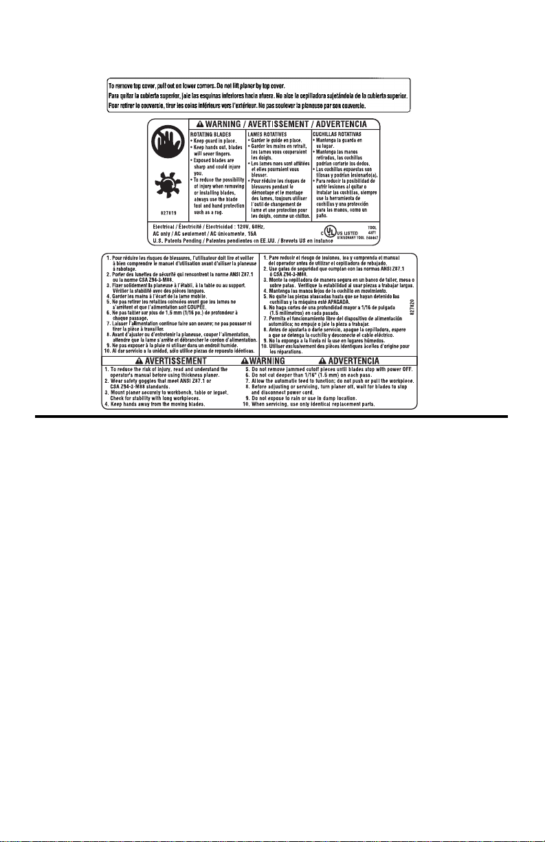
• Find and Read the following labels on the thickness planer:
When Installing Or Moving The Thickness Planer
• Before moving the thickness planer,
turn off and unplug the power cord.
• To reduce the risk of back injury, get
help when you need to lift the thickness planer.
Avoid Dangerous Environment.
• Use the thickness planer in a dry,
indoor place protected from rain.
• Keep work area well lighted.
• Place the thickness planer so neither
the user nor bystanders are forced to
stand in line with the wood. Thrown
debris could injure people in its path.
• Place the thickness planer where there
is room for moving the workpiece
through the entire cut.
To reduce the risk of injury from
unexpected thickness planer
movement:
• Put the thickness planer on a firm
level surface where there is plenty
of room for handling and properly
supporting the workpiece.
• Support the thickness planer so the
tables are level and the thickness
planer does not rock.
• Bolt or clamp the thickness planer to
the table/bench if it tends to slip,
walk, slide or tip over during work
such as planing long, heavy boards.
• Never Stand On Tool. Serious
injury could occur if the tool tips or
you accidentally hit the cutting tool.
Do not store anything above or near
the tool where anyone might stand
on the tool to reach them.
T o reduce the risk of injury or
death from electrical shock:
Make sure your fingers do not touch
the plug’s metal prongs when plugging or unplugging the thickness
planer.
4
Page 5

Before Each Use
Inspect your thickn ess planer.
• Disconnect The Thickness Planer
to reduce the risk of injury from accidental starting before changing the
setup, changing the blade or adjusting anything.
Check For Damaged Parts. Check
for:
• Proper alignment of moving parts,
• Damaged electric cords,
• Binding of moving parts,
• Broken parts,
• Stable mounting,
• Other conditions that may affect the
way the thickness planer works.
Before each use, make sure area
under the cutter head and feed rollers
is clear.
If any part of this thickness planer is
missing, bent, or broken in any way,
or any electrical parts don’t work, turn
the thickness planer off and unplug it.
Replace damaged, missing, or failed
parts before using the thickness
planer again.
To reduce possibility of thrown
pieces, make sure the knives are
properly installed and the knife lock
screws are tight.
Use sharp knives. Dull or knicked
knives tend to “pound” and chew at
the wood, causing kickbacks.
Replace dull or damaged planer
knives.
Make sure the dust chute is in place.
Keep Guards In Place, in working
order, and in proper adjustment.
Maintain Tools With Care. Keep the
thickness planer clean for best and
safest performance. (See “Maintenance” section) DON’T lubricate any
part of the thickness planer while the
knives are rotating.
To Reduce The Risk Of Injury From Jams, Slips Or Thrown Pieces
• Use Only Recommended Accessories. (See “Accessory” section).
Consult this Operator’s manual for
recommended accessories. Follow
the instructions that come with the
accessories. The use of improper
accessories may cause injury to
persons.
• Keep Work Area Clean. Cluttered
areas and benches invite accidents. Floor must not be slippery.
To reduce the risk of burns or other
fire damage, never use the thickness
planer near flammable liquids, vapors
or gases.
Plan Ahead To Protect Your Eyes, Hands, Face and Ears
Know Y our Thickness Planer. Read
and understand the operator’s manual and labels affixed to the tool.
Learn its applications and limitations
as well as the specific potential hazards peculiar to this tool.
To reduce the risk of injury from accidental contact with moving parts,
don’t do layout, assembly, or setup
work on the thickness planer while
any parts are moving.
Reduce the Risk of Accidental
Starting. Make sure switch is “OFF”
before plugging thickness planer into
a power outlet.
Plan your work.
Use the right tool. Don’t force planer
to do a job it was not designed to do.
NOTE: Advises you of information or
instructions vital to the operation or
maintenance of the equipment.
5
Page 6

Safety Instructions for Thickness Planer (continued)
Dress For Safety
Any power tool can throw foreign
objects into the eyes. This can result
in permanent eye damage. Wear
safety goggles (not glasses) that
comply with ANSI Z87.1 (or in Canada CSA Z94.3-99) shown on package. Everyday eyeglasses have only
impact resistant lenses. They are not
safety glasses. Safety goggles are
available at many local retail stores.
Glasses or goggles
not in compliance
with ANSI or CSA
could seriously hurt
you when they
break.
• Do not wear loose clothing, gloves,
Inspect Your Workpiece
• Make sure there are no nails or foreign objects in the part of the workpiece to be planed.
• Use quality lumber. Knives last
longer and cuts go smoother on
good wood.
• Do not plane undersized wood.
Boards which are thinner than 1/8"
neckties or jewelry (rings, wrist
watches) They can get caught and
draw you into moving parts.
• Wear nonslip footwear.
• Tie back long hair.
• Roll long sleeves above the elbow.
• Noise levels vary widely. To reduce
the risk of possible hearing damage,
wear ear plugs or muffs when using
thickness planer for hours at a time.
• For dusty operations, wear a dust
mask along with safety goggles.
Keep hands at least (8") 20cm from
the outfeed. Don’t grip board tightly or
pull board. A sudden kickback could
pull hand into cutters.
Keep hands away from moving parts.
or shorter than 12" could split while
being planed.
• Plane boards (12”) 30cm or longer
only. Short boards can jam or split
and cause dangerous kickbacks.
• Use for solid wood and wood products only. Do not plane metals, plastics or laminated materials.
Whenever Thickness Planer Is Running
WARNING: Don't allow familiar-
ity (gained from frequent use of
your thickness planer) to cause a
careless mistake. A careless fraction of a second is enough to cause
a severe injury.
Before starting to plane a board,
watch the thickness planer while it
runs. If it makes an unfamiliar noise
or vibrates a lot, stop immediately.
Turn the thickness planer off. Unplug
the thickness planer. Do not restart
until finding and correcting the problem.
Plan the way you will hold the
workpiece from start to finish:
• Avoid awkward operations and
hand positions where a sudden slip
could cause fingers or hand to move
into the knives.
• Don’t Overreach. Keep good foot-
ing and balance.
• Do not force the cut. Slowing or
stalling the motor will overheat it.
Allow the automatic feed to function
properly.
• Support workpiece. Do not allow
the board to hang from the planer.
6
Page 7

• Never use another person as a sub-
stitute for a table extension, or as
additional support for a workpiece
that is longer or wider than the basic
thickness planer table or to help
feed, support or pull the workpiece.
Take Precautions Against Kickback.
Do not permit anyone to stand or
cross in line with the path of the board
through the thickness planer. A kickback or thrown debris will travel in this
direction.
Keep Children Away. Keep all visi-
ness planer. Make sure bystanders
are clear of the thickness planer and
workpiece.
Let the blade reach full speed before
planing.
Turn switch off and unplug tool before
inspecting, adjusting or repairing the
planer.
Before freeing jammed material:
• Turn switch “OFF”.
• Wait for all moving parts to stop.
• Unplug the thickness planer.
tors a safe distance from the thick-
Before Leaving The Thickness Planer
Never Leave Tool Running Unattended. Turn power off. Wait for all
moving parts to stop.
Make workshop child-proof. Lock
the shop. Remove yellow switch key
and store away from tool. Disconnect
master switches. Store away from
children and others not qualified to
use the tool.
WARNING:
The operation of any power tool can result in foreign objects being thrown
into your eyes, which can result in severe eye damage. Before beginning tool
operation, always wear safety goggles of safety glasses with side shields
and a full face shield when needed. We recommend Wide Vision Safety
Mask for use over eyeglasses or standard safety glasses with side shields.
Always wear eye protection which is marked to comply wtih ANSI Z87.1.
Look for this symbol to point out important safety precautions. It
means attention!!! Your safety is involved.
Glossary of Terms for Woodworking
Bed - The combination of infeed and outfeed table surfaces which support the
workpiece during a cutting operation.
Cutter Head - The cutter head is a rotating piece with two adjustable knives. The
cutter head removes material from the
workpiece.
Depth of cut - A term used to indicate
how deep into the workpiece the cutter
knives will cut.
Gum - A sticky, sap based residue from
wood products.
Infeed Table - The section of the thickness planer upon which the workpiece is
placed before being pushed into the cutter
head.
Kickback - An uncontrolled grabbing and
throwing of the workpiece back toward the
operator by the rotating cutter head.
Leading End- The end of the workpiece
which is pushed into the cutter head first.
Outfeed Table - The section of a thickness planer which supports the workpiece
after it passes under the cutter head.
SAVE THESE INSTRUCTIONS
7
Page 8
Glossary of Terms for Woodworking (continued)
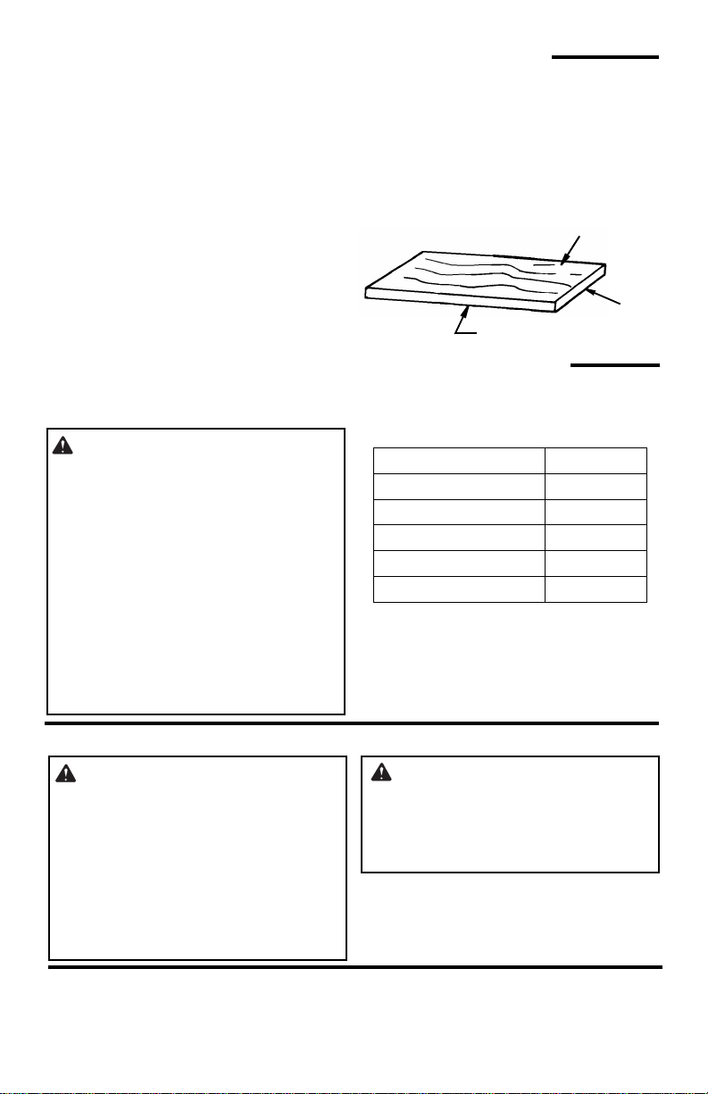
Face
Planing - Removing wood from the wid-
est surface or face of a board so as to
make it flat and smooth.
Resin - A sticky, sap based substance
that has hardened.
Revolutions Per Minute (RPM) - The
number of turns completed by a spinning
object in one minute.
Snipe - The localized variation in workpiece thickness.
Throw-Back -
Throwing of pieces in a manner similar to
a kickback.
Trailing End
The workpiece end last cut by the knives.
Workpiece
The item on which the cutting operation is
being performed. The surfaces of a workpiece are commonly referred to as faces,
ends and edges.
Edge
Motor Specifications and Electrical Requirements
Power Supply and Motor Specifications
W ARNING: To reduce the risk of
electrical hazards, fire hazards or
damage to the tool, use proper circuit protection. Your tool is wired at
the factory for operation using the
voltage shown. Connect tool to a
power line with the appropriate voltage and a 15-amp branch circuit.
Use a 15-amp time delay type fuse
or circuit breaker. To reduce the risk
of shock or fire, replace power cord
immediately if it is worn, cut, or
damaged in any way.
The A-C motor used on this tool is an universal non-reversible type, having the following specifications:
Voltage 110-120
Amperes 15
Hertz (Cycles) 60
Phase Single
Cuts per minute-CPM 18,000
Rotation of Shaft Clockwise
End
General Electrical Connections
DANGER: To reduce the risk of
electrocution:
1. Use only identical replacement
parts when servicing. Servicing
should be performed by a qualified service technician.
2. Do not use in rain or where floor
is wet. This tool is intended for
indoor use only.
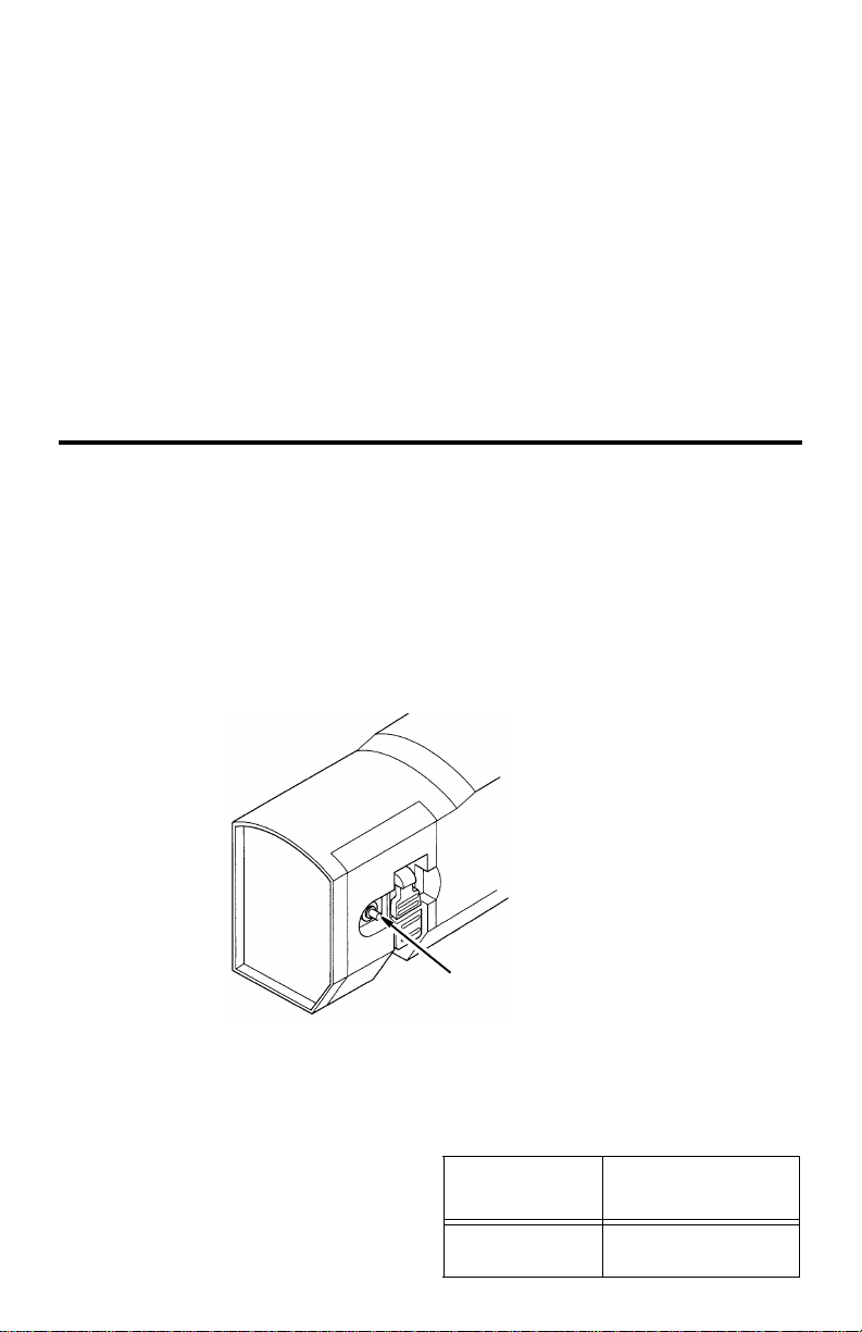
110-120 Volt, 60 Hz. Tool Information
NOTE: The plug supplied on your tool
may not fit into the outlet you are planning
WARNING: To reduce the risk
of electrical shock do not permit
fingers to touch the terminals or
plug when installing or removing
the plug to or from the outlet.
If power cord is worn or cut, damaged in
any way, have it replaced immediately.
to use. Your local electrical code may
require slightly different power cord plug
8
Page 9
connections. If these differences exist
refer to and make the proper adjustments
per your local code before your tool is
plugged in and turned on.
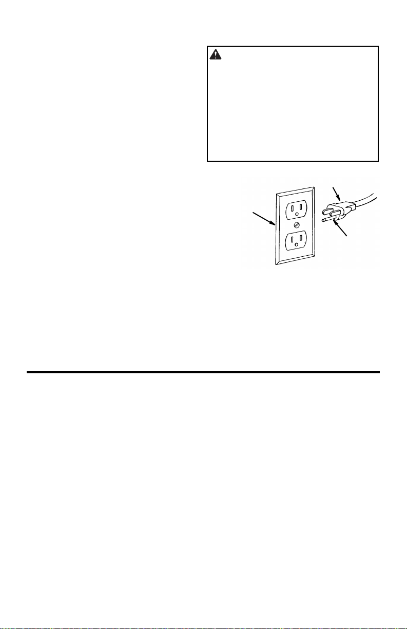
In the event of a malfunction or breakdown, grounding provides a path of least
resistance for electric current to reduce
the risk of electric shock. This tool is
equipped with an electric cord having an
equipment grounding conductor and a
grounding plug, as shown. The plug must
be plugged into a matching outlet that is
properly installed and grounded in accordance with all local codes and ordinances.
Do not modify the plug provided. If it will
not fit the outlet, have the proper outlet
installed by a qualified electrician.
Improper connection of the equipment
grounding conductor can result in a risk of
electric shock. The conductor with insulation having an outer surface that is green
with or without yellow stripes is the equipment grounding conductor. If repair or
replacement of the electric cord or plug is
necessary, do not connect the equipmentgrounding conductor to a live terminal.
If the grounding instructions are not completely understood, or if you are in doubt
as to whether the tool is properly
grounded check with a qualified electrician or service personnel .
WARNING: If not properly
grounded, this tool can cause an
electrical shock, particularly when
used in damp locations, in proximity
to plumbing, or out of doors. If an
electrical shock occurs there is the
potential of a secondary hazard,
such as your hands contacting the
knives.
Properly
Grounded
3-Prong Outlet
3-Prong Plug
Grounding
Prong
Motor Safety Protection
IMPORTANT: To reduce the risk of motor
damage, this motor should be blown out
or vacuumed periodically to keep sawdust
from interfering with normal motor ventilation.
1. Connect this tool to a power source
with the appropriate voltage for your
model and a 15-amp branch circuit with
a 15-amp time delay fuse or circuit
breaker. Using the wrong size fuse can
damage the motor.
2. If the motor won’t start, turn off the
power switch immediately and unplug
the tool. Check the cutter head to make
sure it turns freely. If the head is free,
try to start the motor again. If the motor
still does not start, refer to the "Troubleshooting Chart."
9
Page 10
Motor Specifications and Electrical Requirements (continued)
r
3. Fuses may "blow" or circuit breakers
may trip frequently if:
a. Motor Is Overloaded-Overloading
can occur if you feed too rapidly or
make too many start/stops in a short
time.
b. Line voltages should not be more
than 10% above or below the nameplate voltage. For heavy loads, however, the voltage at motor terminals
must equal the voltage specified for
your model.
c. Improper or dull cutter knives are
used.
Thermal Overload Protector
This planer is equipped with a thermal
overload protector device which will automatically “trip” and cause the planer to
shut down if the planer is overheating due
to continuous heavy cutting.
The planer overload protector can only be
reset manually by the user after the
planer had been allowed to adequately
cool. Allow 15-30 minutes.
NOTE: Do not continuously use the thickness planer set at maximum depth of cut
(1/8") and at full 13" width of cut. Continuous use at maximum cutting capacity will
damage your motor.
4. Most motor troubles may be traced to
loose or incorrect connections, overload, low voltage (such as small size
wire in the supply circuit) or to overly
long supply circuit wire. Always check
the connections, the load and the supply circuit whenever motor doesn’t work
well. Check wire sizes and length with
the Wire Size Chart.
Should the overload protector “trip”:
1. Turn switch off.
2. Raise carriage and remove board.
3. Wait 15-30 minutes.
4. Push in on the reset button.
5. If motor has cooled, button will remain
in.
Thermal Overload Protecto
Wire Sizes
NOTE: Make sure a proper extension
cord is used and it is in good condition.
The use of any extension cord will cause
some loss of power. To keep this to a minimum and to prevent overheating and
motor burn-out, use the table below to
determine the minimum wire size
(A.W.G.) extension cord.
Reset Button
Use only 3-wire extension cords which
have 3-prong grounding type plugs and 3pole receptacles which accept the tools
plug.
Extension Cord
50-100 Ft.
10
Length
0-50 Ft.
Wire Sizes Required
for (A.W.G.)
14
10
Page 11
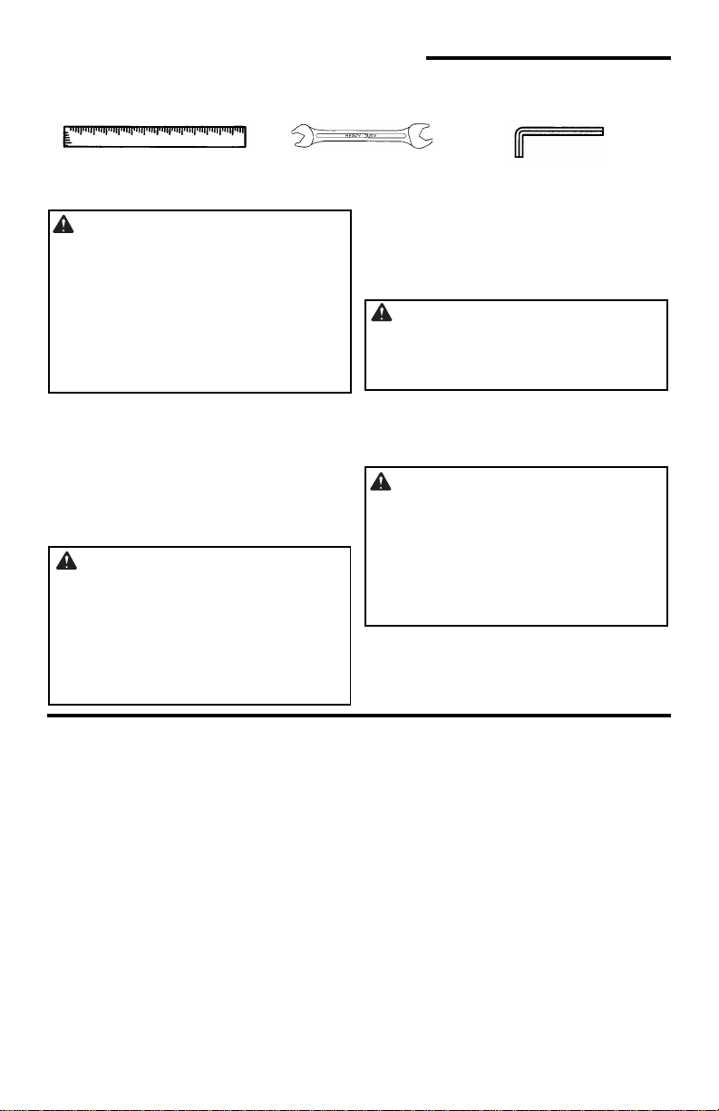
Unpacking and Checking Contents
Tools Needed
Tools Required for Alignment
Straightedge
Wrench 8mm/10mm
Unpacking
W ARNING: To reduce the risk of
injury from unexpected starting or
electrical shock, do not plug the
power cord into a source of power
during unpacking and assembly.
This cord must remain unplugged
whenever you are working on the
thickness planer.
Your thickness planer, is shipped complete in one box.
NOTE: Every RIDGID 13" thickness
planer is tested at the factory to insure its
performance. You may see a small
amount of wood dust and chips on your
new planer.
WARNING: If any part is miss-
ing or damaged, do not plug the
thickness planer in until the missing
or damaged part is correctly
replaced. To reduce the risk of electric shock, use only identical
replacement parts.
Hex “L” Wrench 4mm
Remove the protective oil that is applied
to all unpainted metal surfaces. Use any
ordinary household type grease and spot
remover.
WARNING: To reduce the risk of
fire or toxic reaction, never use gasoline, naptha or similar highly volatile solvents.
Apply a coat of paste wax to the table.
Wipe all parts thoroughly with a clean, dry
cloth.
WARNING: For your own safety,
never connect plug to power source
outlet until all assembly steps are
complete, and you have read and
understand the safety and operating instructions.
List of Loose Parts
NOTE: Before beginning assembly, check
that all parts are included. If you are missing any part, do not assemble the thickness planer. Call 1-866-539-1710 to get
the missing part. Sometimes small parts
can get lost in packaging material. Do not
throw away any packaging until thickness
planer is put together. Check packaging
for missing parts before contacting
RIDGID.
11
Page 12

Unpacking and Checking Contents (continued)
L
Bolt
The following parts are included:
Item Description Qty
A Thickness Planer ...........................1
B * Magnetic Knife Handling Tool ........ 1
C * Hex “L” Wrench 4mm ....................1
D * Open End Wrench 8mm/10mm..... 1
E Replacement Blades/Blade Case .. 1
(stored under rear table)
F Operator’s Manual .........................1
G Bag of Loose Parts ........................1
(Contains the following items)
H Handle............................................1
A
Item Description Qty
J Screw M5 x 0.8-10......................... 1
K Switch Key.....................................1
L Upper Leg...................................... 4
M Lower Leg......................................4
N Long Upper Stiffener...................... 2
P Long Lower Stiffener...................... 2
Q Short Upper Stiffener ..................... 2
R Short Lower Stiffener..................... 2
S Foot ............................................... 4
T Hardware pack, Legset Hardware. 1
* Supplied in “Tool Box”
B
E
F
L
M
N
Assembling Legset
1. Locate the following parts:
4 Lower Legs
4 Upper Legs
2 Long Upper Stiffeners
2 Short Upper Stiffeners
2 Long Lower Stiffeners
2 Short Lower Stiffeners.
2. From the leg set hardware bag find the
following:
4Feet
32 Carriage Bolts M8 x 1.25
32 Hex Flanged Nuts M8 x 1.25
NOTE: Hardware not shown actual size.
C
D
P
Q
R
Lower Leg
ong Upper
Stiffener
Short Upper
H
Stiffener
G
J
K
S
T
Upper Leg
Long Lower
Stiffener
Short Lower
Stiffener
12
Foot
Flange Nut
Page 13

Assembling Upper and Lower Legs
t
L
r
1. Locate the following parts and hard-
ware:
8 Cariage Bolts M8 x 1.25
8 Hex Flanged Nuts M8 x 1.25
4 Upper Legs
4 Lower Legs
4Feet
2. Position the lower leg inside the upper
leg as shown. Place a bolt only through
the bottom hole of the upper leg and
through the bottom hole of the lower
leg. Attach a nut but only finger tighten.
3. Repeat for other three leg assemblies.
4. Asemble foot to bottom of lower leg.
Repeat for other three leg assemblies.
Carriage Bolts
M8 x 1.25
Upper Leg
Nut
Bolt
Bottom
Hole
Foot
Hex Flanged Nut
M8 x 1.25
Lower Leg
Upper Leg
Bottom
Hole
Nu
Bolt
Lower
Leg
Assembling Lower Stiffeners
1. Locate the following parts and hard-
ware:
8 Carriage Bolts M8 x 1.25
8 Hex Flanged Nuts M8 x 1.25
2 Long Lower Stiffeners
2 Short Lower Stiffeners
Carriage Bolts
M8 x 1.25
ong Lower
Stiffener
13
Hex Flanged Nut
M8 x 1.25
Short Lowe
Stiffener
Page 14

Assembling Legset (continued)
e
er
S
N
Long
r
Assembling Lower Stiffeners (cont.)
2. Assemble the lower stiffeners to the
legs as shown. Finger tighten the nuts.
Make sure:
a. The long and short lower stiffeners fit
inside the legs.
b. The short stiffeners must be assem-
bled on opposite sides of the leg set.
(The same for the long stiffeners.).
Assembling Upper Stiffeners
1. Locate the following parts and hardware:
16Carriage Bolts M8 x 1.25
16Hex Flanged Nuts M8 x 1.25
2 Long Upper Stiffeners
2 Short Upper Stiffeners
Nut
Stiffener
Carriage Bolts
M8 x 1.25
Carriag
Bolt
Short
Lower
Hex Flanged Nut
M8 x 1.25
2. Assemble the upper stiffeners to the
legs as shown. Finger tighten nuts.
Make sure:
a. The long upper stiffeners go over the
short upper stiffeners. Make sure the
stiffeners go inside the legs.
b. The short upper stiffeners go oppo-
site each other, same as the long
upper stiffeners.
c. The planer mounting holes in the top
of the legset are aligned.
3. Go back and tighten all nuts.
Long Upper
Stiffener
Carriage
Short Upp
Stiffener
Upper
Stiffene
Bolt
ut
hort Upper
Stiffener
Short
Long
Lower
Stiffener
Lower
Stiffener
14
Page 15

Mounting The Thickness Planer
Mounting on Legset
W ARN ING: To reduce the risk of injury from unexpected planer movement:
a. Unplug electric cord.
b. To reduce the risk of back injury, hold the tool close to your body when
lifting. Bend your knees so you can lift with your legs, not your back. Lift
by using the hand-hold areas at each side of the bottom of the base or by
the carrying handles.
c. Place the planer so other people cannot stand behind it. Thrown debris
could injure people in its path.
d. Place the planer on a firm, level surface where there is plenty of room for
handling and properly supporting the workpiece.
e. Bolt or clamp the planer to its support.
Mounting Thickness Planer on Supplied Legset
1. Locate 4 hex screws M8 x 1.25 and the
remaining 4 flange nuts and 4 washers
in parts bag.
2. Position leg set at the desired location .
3. Mount the thickness planer as shown
with provided hardware. Only finger
tighten nuts at this time.
If necessary shift the leg set to adjust for
slightly unlevel floor. Securely tighten all
hardware.
Mounting Thickness Planer on Other Legsets or Work Benches
Place the planer in the desired location on
either a workbench or other recommended leg set. The base of the planer
has eight mounting holes. Four smaller
holes for “drywall” screws are labeled B.
Four larger holes for bolts are labeled A
(see illustration). Place a bolt through the
larger holes. Attach a washer and nut and
securely tighten.
Portable Applications
To mount the planer to a 3/4” piece of plywood, use 4, 1/4" bolt holes or
wall screw holes. The mounting board can
then be clamped down to prevent it from
tipping.
the 4 dry-
Work Bench Applications
Mount as specified in portable applications. Check for workpiece clearances to
front and rear of planer.
Mounting Board or Work Surface
A
B
B
15
A
A
A
B
B
Page 16

Installing the Handwheel Knob
1. Locate the handwheel knob and screw
in the loose parts bag.
2. Use the hex “L” wrench from the tool
box to remove the screw from the center of the handwheel and remove the
handwheel from the unit.
3. Place the screw through the back of the
handwheel and secure the screw to the
knob on the front of the handwheel.
4. Place the handwheel back on the elevation shaft and reinstall the screw in
the center of the handwheel.
Alignment (Adjustments)
Extension Assembly Alignment
WARNING: To reduce the risk of
injury from unexpected starting or
electrical shock, do not plug the thickness planer in. The power cord must
remain unplugged whenever you are
adjusting or aligning the thickness
planer.
NOTE: Align only one extension at a time.
Elevate the motor enough to give a proper
view of the table body and clearance of
the knives.
WARNING: Knives are
extremely sharp and could seriously injure your hands or arms.
1. Place a straight edge across table body
and over infeed extension as shown.
Screw
M5 x 0.8-10
Loosen locking nut and adjust each
side of the table until the straightedge
touches the outer edge of table extension. Tighten the locking nuts.
2. Repeat step 1 for outfeed extension.
Planer
Table Body
Knob
~
Table
Locking
Nut
Straightedge
Extension
Adjusting the Thickness Indicator
The elevation indicator is preset at time of
manufacture. To check indicator select a
piece of stock at least 12" long and 3/4"
thick. Set planer to 11/16" and run stock
through planer. Measure wood after planing and if necessary, loosen screws to
adjust elevation indicator to agree with
measurement.
16
Page 17

Getting to Know Your Thickness Planer
1
13
e
11 Brush
0 Thermal Reset
Protector
9 On-Off
Switch
8
Infeed
Table
Cap
7 Material Removal
Indicator
1. Rule. Quickly check the thickness of a
workpiece.
2. Carriage Lock. Firmly “locks” the cut-
ter head assembly to help minimize
snipe.
3. Elevation Handwheel. Raises or low-
ers the cutter head for the desired cut.
Each full revolution of the elevation
handwheel will raise or lower the cutter head 1/16"
4. Preset Thickness Stops. Limits cut-
ter head to predetermined thickness.
5. Elevation Indicator. Indicates the
height the cutter head is from the
table.
6. Mounting Holes. Reduces the risk of
injury from unexpected planer movement. Smaller holes are for “drywall”
screws, larger holes for bolts, nuts
and washers.
7. Material Removal Indicator. Indi-
cates how much material is being
removed.
8. Infeed Table. Supports and guides
the workpiece at the start of a cut.
9. On/Off Switch. Lockable, has remov-
able yellow key which helps to pre-
1 Rule
6 Mounting
Holes
2 Carriage Lock
5 Elevation
Indicator
12 Dust Chute
Knob(s)
Cord Storag
Wrap
3 Elevation
Handwheel
14 Tool
Storage
4 Preset
Thickness
Stops
vent unauthorized use.
15 Outfeed
Table
10.Thermal Reset Protector. Opens the
power line circuit when the motor temperature exceeds a safe level, when
the motor is overloaded, or when a
lower voltage condition exists.
11. Brush Caps. Provides access to
inspect or replace carbon motor
brush.
12.Dust Chute Knobs. Used to attach
dust chute and cover the cutter head.
13.Cord Storage Wrap.
14.Tool Storage. Contains tools and
instructions for changing knives.
15.Outfeed Table. Supports and guides
the workpiece at the end of a cut.
Replacement knives stored under outfeed table.
16.Cutter Head. (Not illustrated) Rotat-
ing cylinder which holds knives.
Located under dust chute.
17.Cutter Head Lock. (Not illustrated)
Red lever, located to the left end of
the cutter head. Automatically activated when dust chute is removed.
17
Page 18

Safety Instructions for Basic Thickness Planer Operations
Before Using The Thickness Planer
W ARNING: To reduce the risk of
mistakes that could cause serious,
permanent injury, do not plug the
thickness planer in until the following steps are completed.
• Completely assemble and align
thickness planer. (See “Assembly”
and “Alignment” sections).
Before Each Use
Inspect your thickness planer.
• Disconnect the thickness planer. To
reduce the risk of injury from accidental starting, unplug the thickness
planer, before changing the setup,
changing the blade or adjusting anything.
Check for Damaged Parts. Check
for:
• Proper alignment of moving parts,
• Damaged electric cords,
• Binding of moving parts,
• Broken parts,
• Stable mounting,
• Other conditions that may affect the
way the thickness planer works.
Before each use, make sure area
under the cutter head and feed rollers
is clear.
If any part of this thickness planer is
missing, bent, or broken in any way,
or any electrical parts don’t work, turn
the thickness planer off and unplug it.
• “See Getting To Know Your thickness Planer” section.
• Review and understand all safety
instructions and operating procedures in this manual.
• Review the maintenance methods
for this thickness planer. (See
“Maintenance” Section).
Replace damaged, missing, or failed
parts before using the thickness
planer again.
To reduce possibility of throwing
pieces, make sure the knives are
properly installed and the knife lock
screws are tight.
Use sharp knives. Dull or knicked
knives tend to “pound” and chew at
the wood, causing kickbacks.
Replace dull or damaged planer
knives.
Make sure the deflector or dust collector is in place.
Keep Guards in Place, in working
order, and in proper adjustment.
Maintain Tools With Care. Keep the
thickness planer clean for best and
safest performance. Follow instructions for lubricating. DON’T lubricate
any part of the thickness planer while
the knives are rotating.
Plan Ahead To Protect Your Eyes, Hands, Face and Ears
Know Your Thickness Planer. Read
and understand the operator’s manual and labels affixed to the tool.
Learn its application and limitations
as well as the specific potential haz-
ards peculiar to this tool.
To reduce the risk of injury from acci-
dental contact with moving parts,
don’t do layout, assembly, or setup
work on the thickness planer while
18
Page 19

any parts are moving.
Reduce The Risk Of Accidental
Starting. Make sure switch is “OFF”
before plugging thickness planer into
a power outlet.
Plan your work.
Dress For Safety
Any power tool can throw foreign
objects into the eyes. This can result
in permanent eye damage. Wear
safety goggles (not glasses) that
comply with ANSI Z87.1 (or in Canada CSA Z94.3-99) shown on package. Everyday eyeglasses have only
impact resistant lenses. They are not
safety glasses. Safety goggles are
available at many local retail stores.
Glasses or goggles not in compliance
with ANSI or CSA could seriously hurt
you when they break.
• Do not wear loose clothing, gloves,
neckties or jewelry (rings, wrist
watches). They can get caught and
draw you into moving parts.
• Wear nonslip footwear.
• Tie back long hair.
• Roll long sleeves above the elbow.
• Noise levels vary widely. To reduce
the risk of possible hearing damage,
wear ear plugs or muffs when using
thickness planer for hours at a time.
• For dusty operations, wear a dust
mask along with safety goggles.
Keep hands at least 20cm (8") from
the outfeed. Don’t grip board tightly or
pull board. A sudden kickback could
pull hand into cutters.
Keep hands away from moving parts.
Inspect Your Workpiece
• Make sure there are no nails or foreign objects in the part of the workpiece to be planed.
• Use quality lumber. Knives last
longer and cuts go smoother on
good wood.
• Do not plane undersized wood.
Boards which are too thin or too
short could split while being planed.
• Plane boards (12”) 30cm or longer
only. Short boards can jam or split
and cause dangerous kickbacks.
• Use for solid wood and wood products only. Do not plane metals, plastics or laminated materials.
Whenever Thickness Planer Is Running
WARNING: Don't allow familiar-
ity (gained from frequent use of
your thickness planer) to cause a
careless mistake. A careless fraction of a second is enough to cause
a severe injury.
Before starting to plane a board,
watch the thickness planer while it
runs. If it makes an unfamiliar noise
or vibrates a lot, stop immediately.
Turn the thickness planer off. Unplug
the thickness planer. Do not restart
until finding and correcting the problem.
19
Page 20

Safety Instructions for Basic Thickness Planer
y
Operations (continued)
Plan the way you will hold the
workpiece from start to finish:
• Avoid awkward operations and
hand positions where a sudden slip
could cause fingers or hand to move
into the knives.
• Don’t Overreach. Keep good foot-
ing and balance.
• Do not force the cut. Slowing or
stalling the motor will overheat it.
Allow the automatic feed to function
properly.
• Support workpiece. Do not allow
the board to hang from the planer.
• Never use another person as a sub-
stitute for a table extension, or as
additional support for a workpiece
that is longer than the basic thickness planer table or to help feed,
support or pull the workpiece.
T a ke Precautions Against Kickback. Do not permit anyone to stand
or cross in line with the path of the
board through the thickness planer. A
kickback or thrown debris will travel in
this direction.
Keep Children Away. Keep all visi-
tors a safe distance from the thickness planer. Make sure bystanders
are clear of the thickness planer and
workpiece.
Let the blade reach full speed before
planing.
Turn switch off and unplug tool before
inspecting, adjusting or repairing the
planer.
Before freeing jammed material:
• Turn switch “OFF”.
• Wait for all moving parts to stop.
• Unplug the thickness planer.
Basic Thickness Planer Operations
Before You Begin
1. Locate the planer where it is intended
to be used. Take into consideration the
length of wood you would normally
plane allowing ample room for infeed
and outfeed operations.
WARNING: Before turning
switch on make sure the dust chute
is correctly installed. The ON-OFF
switch has a locking feature. This
feature is intended to prevent unauthorized use by children and others.
2. Locate the yellow On-OFF switch key
from parts bag. Insert into the switch.
3. To turn planer on, stand to either side of
the planer, never in line with the opening. Insert finger under the switch and
lift key up.
4. To turn planer off push key down.
Never leave the planer until the cutting
head has come to a complete stop.
5. To lock switch in “OFF” position simply
remove the key when in the off position.
Always lock the switch “OFF” when
planer is not in use. Remove key and
keep it in a safe place. Also, in the
event of power failure (all of your lights
go out) turn switch off, lock it by remov-
20
Yellow
On-Off
Switch Ke
Thermal Overload Protector
Reset Button
Page 21

ing the key. This will prevent the planer
from starting up again when the power
comes back on.
Reduce Damage To Knives
The thickness planer is a precision wood
working machine and should be used on
quality lumber.
Do not plane dirty boards, dirt and small
stones are abrasive and will wear the
blade.
Remove nails and staples. The planer
should only cut wood.
Preparing the Work
The thickness planer works best when the
lumber has at least one flat surface.
Use a hand plane or jointer to define a flat
surface.
Twisted or severely warped boards can
jam the planer, rip lumber in half to reduce
the magnitude of the warp.
The work should be fed with the grain,
sometimes the grain will switch directions
in the middle of the cut. If possible, cut the
board in the middle before planing so the
grain direction is correct.
6. Refer to “Thermal Overload Protection”
section for proper use.
Avoid Knots. Heavy cross grain makes
the knots hard, also, they can come loose
and jam the blade.
WARNING: Any particle that
may encounter the planer knives
may be thrown from the planer creating the risk of severe injury.
WARNING: Do not plane a
board which is less than 12" long,
the force of the cut could split the
board and cause a kickback resulting in serious personal injury.
Carriage Lock
The carriage lock (see “Getting To Know
Your Thickness Planer” section) helps to
minimize “snipe” by locking the cutter
head position. Snipe is a change in thickness at either end of the board, caused by
an uneven force on the cutter head when
work is entering or leaving the planer.
Pushing the carriage lock to the left will
release the cutter head assembly. Set
planer to the correct thickness (see
below) and then push the carriage lock to
the right. This will lock the cutter head
assembly in place and help to minimize
snipe.
A snipe may occur when boards are not
supported properly (see “Extension
Assembly Alignment” section).
In a few instances it is impossible to elimi-
nate “snipe”. A slight snipe may still be
noticed. Snipe is more apparent when
deeper cuts are being taken.
To avoid snipe when planing more than
one board of the same thickness, butt the
boards together end to end so they follow
each other closely through the planer.
21
Page 22

Basic Thickness Planer Operations (continued)
Carriage Lock Adjustment
The carriage lock is preadjusted at the
factory. If the carriage lock lever does not
tighten when moved to the lock position,
follow the steps below to adjust.
1. Remove the switch key and unplug the
unit from the wall outlet.
2. Remove the top cover for visibility.
3. Use the hex wrench provided and
remove the screw in the center of the
handwheel. Note the position of the
carriage lock lever.
4. Pull the carriage lock lever straight out.
This will disengage the carriage lock
lever from the mating lock nut.
5. Slightly rotate the carriage lock lever
counterclockwise and reengage the
Elevation Handwheel
W ARNING: To reduce the risk of
electrical shock, unwrap cord from
cord storage before raising or lowering carriage.
Turn the elevation handwheel (see “Getting to Know Your Thickness Planer” sec-
carriage lock lever teeth onto the lock
nut.
Example: If your carriage lock is at a 2
o’clock position before adjustment,
move the lever counterclockwise to a 1
o’clock position.
6. Turn the lock lever clockwise to the lock
position to assure it is tightening (force
to the push the lever is increasing).
Then turn the lever counterclockwise to
the unlock position to assure it
becomes very loose in the unlocked
position. If the lock lever is not tightening in the lock position then repeat
steps 5 & 6.
7. Replace the handwheel, secure the
screw with the hex wrench and reinstall
the top cover.
tion), to set the planer for the correct
depth of cut. The surface the planer will
produce will be smoother if a shallower
depth of cut is used. Each full revolution
of the elevation handwheel will raise or
lower the cutter head 1/16".
Feeding the Work
The feed rate refers to the rate at which
the lumber travels through the planer.
The planer feed is automatic, it will vary
slightly depending on the type of wood cut
and depth of cut.
The operator is responsible for aligning
the work so it will feed properly.
Stand to one side of the planer infeed
table.
Lift the work to the infeed extension by
grasping the edges of the board at
approximately the middle of the length.
Boards longer than 24" should have additional support from free standing material
stands.
Rest the board end on the infeed support
extension and direct the board into the
planer.
Push slightly on the board and allow the
automatic feed to take the board. Release
the board and allow the automatic feed to
function properly. Do not push or pull on
the workpiece.
WARNING: To avoid serious
personal injury do not stand directly
in line with the front or rear of the
planer, when an object is thrown
from the planer it will travel in this
direction.
Move to the rear and receive the planed
lumber by grasping it in the same manner
as it was fed.
Do not grasp any portion of the board
which has not gone past the outfeed
extension.
Repeat this operation on all the boards
which need to be the same thickness.
22
Page 23

NOTE: An assistant must follow the same
precaution as the operator.
The surface that the planer will produce
will be smoother if a shallower depth of
cut is used. See “Material Removal Indicator”.
Feed the work in the direction of the grain.
Wood fed against the grain may result in a
chipped splintered surface. If this occurs
try feeding the other end of the board in
first.
Material Removal Indicator
Indicates the amount of material being
removed on each pass through the
planer. Up to 1/8" max. Make sure the
workpiece is under the Material Removal
Indicator label on the front of the tool.
Recommended maximum depth of cut per
pass through planer:
• 1/8" for material 0-6" in width
• 1/16" for material 6-13" in width
NOTE: Do not continuously use the thick-
ness planer set at maximum depth of cut
(1/8") and at full 13" width of cut. Continuous use at maximum cutting capacity will
damage your motor.
Preset Thickness Stops (Repeat -A -Cu t)
These stops are for repetitive planing to
preset thickness. Planing a workpiece to
one of these common thicknesses can be
easily accomplished:
1. Raise carriage to greater than 1-3/4".
2. Slide the knob to the desired thickness
setting.
3. Turn the elevation handle until the carriage contacts the thickness stop.
4. Lock the carriage lock.
5. Plane the workpiece and check the
thickness. If the thickness is incorrect
follow the adjustment steps below.
Thickness Stop (Repeat-A-Cut) Adjustment
1. Pull the Repeat-A-Cut knob straight
out to remove.
2. Remove the screw on the right side of
the Repeat-A-Cut scale and remove
the cover.
3. Measure the height from the base to
the cutter head knife tip. This can be
done with a scrap piece of board — 11/2" for example.
4. Use the elevation handwheel to adjust
the height to the known thickness piece
of scrap, then remove the piece of
scrap without moving the handwheel.
5. Make sure the Repeat-A-Cut is on the
1-1/2" setting and loosen the lock nut
on the adjustment bolt. Adjust the bolt
to come in full contact with the step
block and tighten the lock nut.
6. Replace the Repeat-A-Cut cover and
secure it with the screw.
23
Page 24

Basic Thickness Planer Operations (continued)
7. Replace the knob.
8. Plane a workpiece and check its thickness. Repeat procedure, if necessary.
Checking for Worn Knives
The condition of knives will affect the precision of the cut.
Observe the quality of the cut the planer
produces to check the condition of the
knives.
Dull knives will tear, rather than sever
wood fibers, and produce a fuzzy appearance.
A raised ridge will occur when dull knives
pound on wood that has a varying density.
If a raised ridge is produced running the
length of the workpiece, the knives have
been nicked. If the nick is small, shift one
knife to the right and the other to the left.
(see “Replacing Knives” section).
For knives replacement and installation
refer to “Replacing Knives” section.
Maintenance
The planer will operate best if it is kept in
good condition. Keep the unit adjusted as
described in the “Operation” section. Also,
the knives must be kept clean and sharp
to ensure the quality of cut and efficiency
of operation. Knives are “double edged”.
When one side becomes dull they may be
turned over and the opposite edge used.
W ARNING: To reduce the risk of
injury from unexpected starting or
electrical shock. Make certain that
the unit is disconnected from the
power source, before attempting to
service, or remove any component.
Lubrication
Motor and cutter head bearings are
sealed and need no lubrication. Height
adjustment guides and elevation screws
should be cleaned of debris and greased
when needed.
Occasionally apply a few drops of light
machine oil to the four support rods to
keep the carriage sliding smooth.
Cleaning the Knives
Gum and pitch will collect on knives and
cause excess friction when working.
Knives will overheat and wear at an accelerated rate. Remove knives and clean
with a gum and pitch remover to keep
knives clean.
Cleaning The Feed Rollers
Excessive gum, pitch and sawdust can
reduce friction of the rubber rollers. Use
alcohol to wipe the rollers.
Motor Ventilation
Check the motor vents periodically while
planing and clear away any sawdust to
avoid motor heating.
Nut
Bolt
24
Page 25

Changing Brushes
W ARNING: To reduce the risk of
electrical shock, fire or injury, use
only parts identical to those identified in the parts list. Reassemble
exactly as original assembly to
reduce the risk of electrical hazards.
Replacing Knives
Your thickness planer is supplied with
double edged knives. Knives should be
replaced or turned 180° to the unused
edges whenever they become dull or
nicked. Keeping a spare set of knives on
hand is recommended. Knives should
always be replaced as a matched set.
WARNING: Exposed knives are
sharp and could injure you. To
reduce the possibility of injury protect your hands with gloves or shop
rag and use the knife tool when
removing or installing knives.
1. Be sure the switch key is removed and
the unit is unplugged from the wall
receptacle.
2. For easier access to the cutter head/
knife assembly remove the upper
cover. See illustration.
3. Loosen the two dust chute knobs and
remove the dust chute.
NOTE: When dust chute is removed
the cutter head lock will engage when
the head is rotated. Do not operate
thickness planer without the dust
chute in place, or your planer will be
damaged
4. Rotate the cutter head until the lock
The carbon brushes furnished will last
approximately 50 hours of running time or
10,000 on/off cycles. Replace both carbon
brushes when either brush has less than
1/4" length of carbon remaining. To
inspect or replace first unplug the planer.
Then turn the brush caps counterclockwise to remove. To reassemble reverse
the procedure. Tighten the brush caps
snugly but do not overtighten.
engages. This will correctly position a
knife and its seven knife lock screws.
WARNING: To reduce the risk of
injury from accidental contact with
the exposed knife, when turning the
knife lock screws, lay a folded shop
rag over the knife or wear a glove.
5. Carefully loosen all seven knife locking screws.
NOTE: Move wrench left to right to
loosen screws.
6. Use the notched end of the Magnetic
Knife Handling Tool to remove the
knife by hooking the notch over the
end of the knife and pulling straight
out.
7. Use the magnet on the Magnetic Knife
Handling Tool to help remove the
knife.
8. If you are changing to the second
edge of the knife, rotate the knife “end
for end” keeping the same flat side
down. This will correctly position the
knife to reinstall. Look closely at the
cutter head side view making sure the
knife is installed as pictured. Knives
should be cleaned of gum and pitch
before reinstalling.
25
Page 26

Maintenance (continued)
r
W ARNING: To reduce the risk of
thrown blades and other cutter
head parts make sure the knife lock
bar containing the seven knife lock
screws is positioned as shown in
the cutter head side view picture.
9. Push the installed knife in firmly.
Visually check that the knife edge
is parallel to the cutter head slot.
10. Tighten the seven (7) knife locking
screws.
NOTE: Move wrench right to left to
tighten.
11. To rotate the cutter head to the next
knife, release the cutter head lock.
Hold down on the red lock lever
located on the left side and rotate the
cutter head.
12. Release the red lock lever and continue to rotate the cutter head until it
locks. This should correctly position
the second knife.
13. Repeat procedures 5 through 10 for
the second knife.
14. Check that all knife lock screws are
tight and reinstall the dust chute.
Knife Lock Screws
Knife Lock Ba
Accessories
Do not use any accessory unless you
have received and read complete instructions for its use.
Wiring Diagram
Switch
Black
White
Green
Power Cord
Motor Lead
Grounding Wire
Power Tool Universal Legset....... AC9910
Dust Collector.............................. AC8640
Replacement Knives ................... AC8630
Over Load
Motor Lead
Motor
26
Page 27

Troubleshooting
Problem Possible Cause Remedy
Snipe
(Gouging at
ends of board)
Fuzzy Grain 1. Planing wood with a
Torn Grain 1. Too heavy a cut
Rough Raised
Grain
Uneven Depth
Cut Side to
Side
Cutter head
Elevation
Adjusts with
Difficulty
Board Thickness Does Not
Match Depth of
Cut Scale
Chain Jumping 1. Sprockets worn
Motor does not
start
Dust chute is
blocked
1. Dull knives
2. Inadequate support of
long boards
3. Lumber not butted
properly
4. Extensions misaligned
high moisture content
2. Knives cutting against
grain
3. Dull knives
1. Dull knives
2. Too heavy a cut
3. Moisture content too
high
1. Blade projection not
uniform
1. Elevation screws dirty
2. Gears or screws worn
3. Friction between casing and covers
1. Indicator not set correctly
2. Knife projection incorrect
2. Chain worn
1. Switch malfunction
2. Overload protector
tripped
3. Supply fuse opens
4. Brushes worn
5. Other
1. Build up of resin under
dust chute
2. Large debris
1. Replace knives per instructions (See
“Replacing Knives” section)
2. Support long boards
3. Butt end to end each piece of stock
as boards pass through planer
4. Adjust extension supports
1. Remove high moisture content from
wood by drying
1. Review “Depth of Cut” section
2. Review “Feeding the Work” section
3. Replace knives per instructions
1. Replace knives per instructions
2. Review “Depth of Cut”
3. Dry the wood or use dried wood
1. Check that end of knife is fully
seated in the cutter head.
1. Clean and lubricate elevation screws
2. Replace
3. Clean, lubricate
1. Adjust indicator/securely tighten
2. Set knife projection correctly (See
“Replacing Knives” section).
1. Replace sprockets
2. Replace chain
1. Have a qualified electrician replace
the ON/OFF switch.
2. Turn power switch off. When planer
temperature adequately cools (allow
15-30 minutes) press overload protector reset button.
3. Replace fuse with a 15 amp time
delay fuse, or circuit breaker.
4. See “Maintenance” section, ”Changing Brushes
5. Get authorized service.
1. Clean dust chute and exhaust area.
2. Clear debris.
27
Page 28

Repair Parts
RIDGID parts are available on-line at www.ridgidparts.com
10
15
14
13
5
Parts List for 13" Thickness Planer
Model No. TP13002
Figure 1
21
20
83
22
29
28
6
12
29
32
23
33
34
30
39
82
24
17
18
19
25
26
16
27
31
40
41
45
42
35
46
43
47
44
48
49
27
50
49
58
10
51
52
57
53
54
55
56
4
3
78
11
80
79
36
76
37
18
2
84
1
85
9
8
7
81
36
77
88
38
74
75
56
71
70
69
87
27
68
62
61
63
73
64
66
60
59
86
65
67
72
28
Page 29

Repair Parts
RIDGID parts are available on-line at www.ridgidparts.com
Parts List for 13" Thickness Planer
Model No. TP13002
Figure 1
Always order by Part Number - Not by Key Number
Key
Part No. Description
No
1
2
3
4
5
6
7
8
9
10
11
12
13
14
15
16
17
18
19
20
21
22
23
24
25
26
27
28
29
30
31
32
33
34
35
36
37
38
39
40
41
42
43
44
45
820380-6
827681
827713
827841
827682
827741
817453-1
827769
827720
820379-6
827717
827719
827726
827766
827724
827754
827721
821065-2
827723
827699
827716
820379-9
827695
827753
827926
813312-6
821102-1
827697
827932
827930
827931
827750
827770
827759
827768
820240-3
827704
827767
827738
827678
827725
827751
827737
820240-6
AC8630
Scr Hex Soc Butt Hd
M6 x 1.0-20
Cap Left
Scale Length
Cover Upper
Cap Right
Pad Upper
Ring Retaining C17
Worm Gear L.H.
Plate Lock Left
*Scr Hex Soc Cap M5 x 0.8-12
Sleeve
Plate Lock Right
Shaft Transmission
Washer 21.5 x 24 x 1
Nut Lock M17 x 2.0
Support
*Washer 12 x 16 x 1
*Scr Soc Set Cup Pt M5 x 0.8-8
Worm Elevation
Handle
Knob Snipe
*Scr Hex Soc Cap M5 x 0.8-10
Chute Dust
Knob Chute
Cover Shroud
*Scr Pan Hd M4 x 0.75-6
*Washer 4.2 x 10 x 0.9
Manifold Air
Gasket Rear
Gasket Right
Gasket Left
Cover
Worm Gear R.H.
Bushing
Screw Elevating R.H.
*Scr Pan Hd M5 x 0.8-6
Plate Dust Chute
Clamp Cord
Spring /Plunger
Frame Upper
Block Support
Lock Cutter Head
Spacer Cutter Head Lock
*Scr Pan Hd M5 x 0.8-12
†Knife Planer
Key
Part No. Description
No
827711
46
827785
47
818654-9
48
827714
49
818469-6
50
827787
51
827793
52
827788
53
827789
54
827786
55
820722-5
56
827680
57
813249-76
58
821151-4
59
813164-6
60
827729
61
827817
62
827739
63
820401-2
64
827733
65
827734
66
827746
67
813312
68
827701
69
827732
70
827762
71
813314-8
72
820257-1
73
827784
74
828677
75
820379-8
76
820379-5
77
827773
78
827772
79
827794
80
817453-4
81
820383-4
82
828027-1
83
828027
84
820383-5
85
821065-1
86
827763
87
SP6452
88
Bar Knife Lock
Screw Knife Lock
*Key 5 x12mm
Collar Knife
*Scr Hex Soc Cap M4 x 0.75-8
Pulley Cutter head
Belt Drive
Nut Hex M6 x 2.0 L.H.
Pulley Motor
Retainer Bearing
Bearing Ball 6203ZZ
Head Cutter (Includes Collar
knife, Retainer Bearing, Bearing Ball and Gear Pinion)
Pin Spring 3 x 8mm
*Screw Hex Hd M5 x 0.8-26
*Nut Hex M5 x 0.8
Rod Step
Nut Special M10 x 1.5
Indicator Depth
Scr Pan Hd M3 x 0.5-16
Rod Pointer Elevating
Spring Coil
Cover Pointer
Scr Pan Cr M4 x 0.75-10
Housing Pointer
Pointer
Nut
Lockwasher Ext Tooth M5
Scr Pan Hd TY TT M5 x 0.8-8
Gear Pinion
Gear Box Asm
*Scr Hex Soc Cap M5 x 0.8-35
*Scr Hex Soc Cap M5 x 0.8-30
Spacer 15 x 20 x 7
Sprocket
Chain
Ring Retaining Ext STW15
Lockwasher M5
Scr Hex Soc Hd Lock M5
Scr Hex Soc Hd Lock
M5x0.8-12
Lockwasher M6
Scr Soc Set Cup Pt M5 x 0.8-5
Bushing 4.2 x 11 x 3
Operator’s Manual
8.5X19X0.8
* Standard Hardware Item - May be purchased locally.
† These replacement parts are available where you purchased your Planer.
29
Page 30

Repair Parts
0
3
RIDGID parts are available on-line at www.ridgidparts.com
Parts List for 13" Thickness Planer
Model No. TP13002
Figure 2
2
19
See Figure
18
26
10
25
27
29
28
30
31
17
9
5
8
7
5
4
2
3
2
1
54
6
4
5
2
10
8
6
58
55
5
9
11
12
13
53
10
51
52
16
15
29
14
50
21
22
59
23
24
40
29
49
41
35
48
41
36
29
28
40
42
44
46
32
37
38
39
34
33
45
43
51
39
47
56
57
30
Page 31

Repair Parts
Parts List for 13" Thickness Planer Model No. TP13002
RIDGID parts are available on-line at www.ridgidparts.com
Cover Side RH
Scale Thickness
Part No. Description
827703
827715
3132333435363738394041424344454647484950515253545556575859
No
Key
Figure 2
Always order by Part Number - Not by Key Number
Spring Coil 7.62x15.75x0.7
Ball Steel
Block Guard
Block Step
Knob Step
Pin Step Block
Spring Flat
Base
Bolt Adjustment
Nut Hex Special M10 x 1.5
Pad Base
Table Front
Nut Lock M10 x 1.5
Rod Support
Cover Side Left
* Scr Pan Hd Ty “TT” M5 x 0.8-8
827718
820257-1
Holder Tool
827684
827771
827760
823742-1
827698
827700
827743
* Nut Hex M6 x 1.0
827730
813164-7
* Scr Pan Hd M5 x 0.8-10
820240-1
827736
827677
827752
827817
* Scr Hex M6 x 1.0-25
827742
821388-3
828028
* Nut Hex M12 x 1.75
813164-10
817449-4
Tool Knife
Wrench Box M8 & M10
Cover Tool Box
Scr Hex Soc Cap M5x0.8-8
* Wrench Hex “L” 4mm
827748
827757
827756
827927
820379-1
Rod Pivot
827728
Ring Retaining
Sprocket
Chain
Part No. Description
817453-4
827772
827794
123456789
No
Key
Spring Coil Left
Block Bearing
827758
827790
Plate Retainer Left
Roller Outfeed
827791
827693
Spring Coil Right
Plate Retainer Right
Roller Infeed
Worm Gear L.H.
Screw Elevating L.H.
Rail Guide
Plate Wear
Table Rear
827705
827694
827688
Case Knife (Knives not included)
827764
* Scr Hex Soc Cap M5 x 0.8-10
* Washer 5.5 x 19 x 2
827755
827792
820379-9
827692
827765
827722
827735
101112131415161718192021222324252627282930
* Washer M8 x 23 x 2
* Screw Hex Hd M8 x 1.25-20
* Scr Pan Hd Ty “TT” M5 x 0.8-6
821063-0
813310
820257-3
Plate Stiffener
Spring Torsion
827928
827744
Plate Side Guard
827731
Cover Side Right
Hub Handwheel
827679
827696
31
Knob Handwheel
Screw Hex Soc.Fl Hd M6 x 1.0-12
* Scr Hex Soc Cap M5 x 0.8-15
* Lockwasher M5
827749
820379-2
820383-4
827929
* Standard Hardware Item - May be purchased locally.
Page 32

Repair Parts
RIDGID parts are available on-line at www.ridgidparts.com
12
21
Parts List for 13" Thickness Planer
Model No. TP13002
Figure 3
1
3
14
4
13
12
15
32
2
23
22
20
16
19
Ke
y
Part No. Description
No.
1
827808
2
827799
3
820240-7
4
827689
5
827740
6
827890
7
827809
8
827811
9
827810
10
821065-3
11
826463-4
12
820383-4
* Standard Hardware Item - May be purchased locally.
† These replacement parts are available where you purchased your Planer.
16
17
18
Always order by Part Number - Not by Key Number
Cord w/plug
Guard Cord
* Screw Pan Hd
M5 x 0.8-20
Housing Switch
Gasket Foam
Motor
(Includes Brushes)
Holder Brush
Brush
Cap Brush
* Screw Hex Soc Set
M5 x 0.8-12
Label RIDGID
* Lockwasher M5
5
6
11
Ke
y
Part No. Description
No.
13
14
15
16
17
18
19
20
21
22
23
827812
820257-1
827807
827806
827708
826347
AC1000
827797
827798
827765
820240-5
Lead Ground
* Screw Pan Hd
Ty “TT” M5 x 0.8-8
Rod Motor Pivot
Switch Reset
Bezel Switch
Switch Locking
† Key Switch
Screw Special
Clamp Cord
* Washer 5.5 x 19 x 2
* Screw Pan Hd
M5 x 0.8-30
9
8
7
10
(Includes Nut)
Page 33

Repair Parts
2
RIDGID parts are available on-line at www.ridgidparts.com
Parts List for 13" Thickness Planer
Model No. TP13002
Figure 4 - Legstand
11
11
11
8
9
1
11
1
5
3
4
6
7
10
9
9
3
3
6
7
6
7
2
4
3
5
6
7
Always order by Part Number - Not by Key Number
Key
Part No. Descripti on
No.
1
829635
2
829636
3
829634
4
829637
5
829638
6
829633
7
829632
* Standard Hardware Item - May be purchased locally
Stiffener Upper Long
Stiffener Upper Short
Leg Upper
Stiffener Lower Long
Stiffener Lower Short
Leg Lower
Foot
33
Key
No.
8
9
10
11
813310-10
829631
821063-2
821103
Part No. Description
Screw Hex
M8 x 1.25-65
Nut Hex Flanged
M8 x 1.25
Washer
M8 x 16 x 1.6
Bolt Cup Sq Neck
M8 x 1.25
Page 34

Notes
34
Page 35

Notes
35
Page 36

RIDGID¨ HAND HELD AND STATIONARY POWER TOOL
LIMITED THREE YEAR WARRANTY AND 90-DAY
SATISFACTION GUARANTEE POLICY
This product is manufactured by One World Technologies, Inc.,
under a trademark license from Ridgid, Inc. All warranty communications should be directed to One World Technologies,
Inc., attn: RIDGID handheld and stationary power tool technical
service at (toll free) 1-866-539-1710.
90-DAY SATISFACTION GUARANTEE POLICY
During the first 90 days after the date of purchase, if you are
dissatisfied with the performance of this RIDGID tool for any
reason you may return the tool to the dealer from which it was
purchased for a full refund or exchange. To receive a replacement tool you must present proof of purchase and return all
original equipment packaged with the original product. The
replacement tool will be covered by the limited warranty for the
balance of the three year warranty period.
WHAT IS COVERED UNDER THE LIMITED THREE YEAR
WARRANTY
This warranty covers all defects in workmanship or materials in
this RIDGID tool for the three year period from the date of purchase. This warranty is specific to this tool. Warranties for other
RIDGID products may vary.
HOW TO OBTAIN SERVICE
To obtain service for this RIDGID tool you must return it, freight
prepaid, to an authorized RIDGID service center for hand held
and stationary power tools. You may obtain the location of the
authorized service center nearest you by calling (toll free) 1866-539-1710 or by logging on to the RIDGID website at
www.ridgid.com. When requesting warranty service, you must
present the proof of purchase documentation, which includes a
date of purchase. The authorized service center will repair any
faulty workmanship, and either repair or replace any defective
part, at our option at no charge to you.
WHAT IS NOT COVERED
This warranty applies only to the original purchaser at retail
and may not be transferred. This warranty only covers defects
arising under normal usage and does not cover any malfunction, failure or defect resulting from misuse, abuse, neglect,
alteration, modification or repair by other than an authorized
service center for RIDGID branded hand held and stationary
power tools. RIDGID, INC. AND ONE WORLD TECHNOLOGIES, INC. MAKE NO WARRANTIES, REPRESENTATIONS
OR PROMISES AS TO THE QUALITY OR PERFORMANCE
OF ITS POWER TOOLS OTHER THAN THOSE SPECIFICALLY STATED IN THIS WARRANTY.
ADDITIONAL LIMITATIONS
To the extent permitted by applicable law, all implied warranties, including warranties of MERCHANTABILITY or FITNESS
FOR A PARTICULAR PURPOSE, are disclaimed. Any implied
warranties, including warranties of merchantability or fitness for
a particular purpose, that cannot be disclaimed under state law
are limited to three years from the date of purchase. One World
Technologies, Inc. is not responsible for direct, indirect, incidental or consequential damages. Some states do not allow
limitations on how long an implied warranty lasts and/or do not
allow the exclusion or limitation of incidental or consequential
damages, so the above limitations may not apply to you. This
warranty gives you specific legal rights, and you may also have
other rights which vary from state to state.
Stock No. TP1300LS Model No. TP13002
Serial No. ________ Model and serial numbers
may be found on the center of base below outfeed table. You should record serial number in a
safe place for future use.
QUESTIONS OR COMMENTS?
CALL 1-866-539-1710
One World Technologies, Inc.
Hwy. 8
Pickens, SC 29671
Part No. SP6452 Form No. SP6452 Printed in Taiwan 9/03
www.ridgid.com
Please have your Model Numbe r and Serial
Number on hand when calling.
 Loading...